Webfleet LINK 740 User manual

LINK 740
Installation Guide
1586894820069 - Draft - 2020-06-05
LINK 740
Installation Guide
1586894820069 - Draft - 2020-06-05

Contents
Installation...................................................................................................................................... 4
Read me first......................................................................................................................................... 5
Congratulations................................................................................................................................5
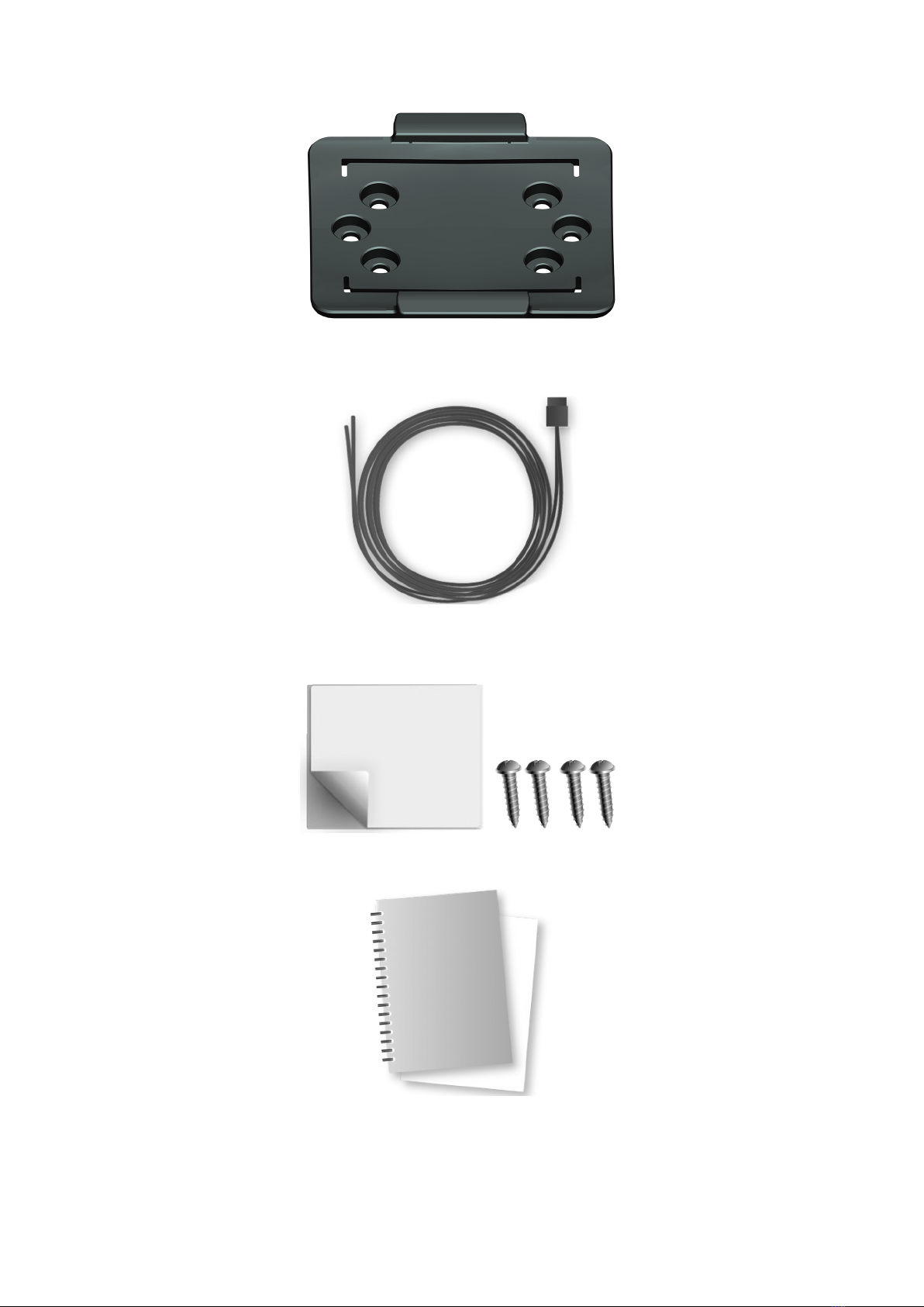
hat’s in the box.................................................................................................................................. 6
hat you need for the installation..................................................................................................8
Safety first..............................................................................................................................................9
Important safety notices and warnings............................................................................................9
Connection overview............................................................................................................................11
Connection overview: Power/CAN cable........................................................................................ 11
Connection overview: 12 PIN IO cable...........................................................................................12
Connection overview: 1 wire......................................................................................................... 12
Connecting to the CAN bus.................................................................................................................13
Connecting to power........................................................................................................................... 14
Choosing the correct position.............................................................................................................. 15
Mounting the LINK 740....................................................................................................................... 16
Attaching the holder using the adhesive strip................................................................................16
Attaching the holder using self-tapping screws............................................................................. 17
Mounting the external GNSS antenna........................................................................................... 18
Testing operation................................................................................................................................. 20
Testing operation with the LINK Toolkit app................................................................................. 20
Power or Ignition test....................................................................................................................20
Mobile network reception test.......................................................................................................20
Activating the LINK 740.......................................................................................................................21
Diagnostics........................................................................................................................................... 22
Monitoring operation.....................................................................................................................22
Support.......................................................................................................................................... 23
Resetting the LINK 740........................................................................................................................ 24
Restarting your LINK 740...............................................................................................................24
Resetting your LINK 740 to factory settings.................................................................................. 24
Technical data......................................................................................................................................25
Appendix: Using the I/O connector...................................................................................................... 28
iring digital inputs...................................................................................................................... 28
iring the digital output............................................................................................................... 30
Using the IN and OUT for changing the logbook mode.................................................................31
Using the input IN for changing the logbook mode...................................................................... 31
Using the input IN for idle time reporting..................................................................................... 31
Addendum.....................................................................................................................................32
Important Safety Notices and arnings........................................................................................ 33
Prohibited uses.............................................................................................................................. 34
CE mark and Radio Equipment Directive for LINK 740...................................................................34
FCC information for the user......................................................................................................... 34
Specific Absorption Rate (SAR) compliance.................................................................................... 36
Button battery warning..................................................................................................................36
Environmental and Battery information..........................................................................................36
Triman logo................................................................................................................................... 37
Operating temperature.................................................................................................................. 37
EEE – e-waste disposal............................................................................................................... 37
How ebfleet Solutions uses your information............................................................................. 37
Exposure limits...............................................................................................................................38
Mobile networks............................................................................................................................38
Technical Specifications..................................................................................................................38
Model numbers..............................................................................................................................39
Responsible party in North America...............................................................................................39
2

Responsible party in Chile..............................................................................................................39
Responsible party in Mexico.......................................................................................................... 39
Emmisions information for Canada................................................................................................ 39
Mexico........................................................................................................................................... 39
Chile...............................................................................................................................................40
arning for Australia.....................................................................................................................40
Notice for New Zealand.................................................................................................................40
Notice for South Africa..................................................................................................................40
Customer support contact............................................................................................................. 40
Certification for Australia............................................................................................................... 40
Customer support contact (Australia and New Zealand)................................................................ 40
This document............................................................................................................................... 41
EBFLEET Telematics Service Platform...........................................................................................41
Accessories supplied with this device.............................................................................................41
Accessories not supplied with this device...................................................................................... 41
Terms and conditions: Limited warranty and EULA reference.........................................................41
Copyright notices...........................................................................................................................41
Bluetooth®.............................................................................................................................. 41
OpenSynergy............................................................................................................................42
Copyright (c) 2018 - Tcl/Tk - Regents of the University of California, Sun Microsystems, Inc.,
Scriptics Corporation, and other parties...................................................................................42
Webfleet Solutions Limited Warranty...........................................................................................44
3

Installation
4

Read me first
Con ratulations
You have chosen the LINK 740, a core hardware component from EBFLEET. ith EBFLEET you are al-
ways connected to your vehicles out on the road in a smart and easy way.
LINK 740 is a GNSS receiver and mobile network module in one unit, always providing the vehicle’s current
position.
hen used with a compatible Driver Terminal, you can easily handle orders, as well as text and status mes-
sages. You can receive traffic information, and you are warned when you are driving or cornering too fast.
And you can get information about how much fuel you have used.
5

What’s in the box
•LINK 740
1. Yellow LED - connection status indicator.
2. Green LED - system status indicator.
3. Reset button.
4. Service/Update Mini-USB-cable connector.
5. 1- ire-Interface.
6. I/O-cable connector.
7. Power/CAN connector.
8. CAN DIP switch (sealed).
9. GNSS antenna connector.
6

•Holder
•Power/CAN cable
•Fixings - 1 adhesive strip, 4 self-tapping screws and a cleaning tissue
•Basic installation guide and additional QR code labels
7

What you need for the installation
Before starting the installation of your LINK 740, read the installation instructions and the safety notices and
warnings carefully and make sure you have the following:
•The Contract Confirmation letter including the Activation Code.
•A device with internet connection that is able to scan QR codes, has the LINK Toolkit app installed and
the necessary LINK Tookit login credentials.
•The QR code of the LINK 740 (on the device label or on the additional QR code label).
•All parts contained in the box.
•A connection to the vehicle’s power supply that is fused with max. 10 A.
•A place with a clear view of the sky where you can move your vehicle to check GNSS reception.
•A Driver Terminal that is compatible with LINK 740* - optional.
* To check available LINK 740 accessories or device compatibility please visit https://www.webfleet.com/
products
8

Safety first
Important safety notices and warnin s
Important: Read the following safety instructions carefully. Read the instructions in this document carefully.
ebfleet Solutions accept no liability for damage that results from disregarding the safety instructions. This
document is part of the product. Keep it in a safe place. If you pass the unit on to a new user, make sure
you give them this document as well.
Positionin
Position the device in such a way that it doesn’t block or interfere with your view of the road, the controls in
your vehicle, or the rear-view mirrors and airbags.
Dan er of explosion
Parts of this product can cause sparks that can lead to explosions. This may endanger human health and life.
Do not use the unit in areas with high risk of explosion. hen using this product in a vehicle fuelled by liq-
uefied gas, follow the safety regulations of the country in which the vehicle is operated.
Dama e caused throu h improper installation
The installation and initial operation of the unit must be performed by authorised personnel only, for exam-
ple, a qualified radio dealer or an automotive electronics workshop.
Risk of injury in case of accidents
Do not mount the unit or accessories in the inflation area of airbags or in the impact area for the head or
knees. Choose an installation location that will avoid interference with displays, safety equipment and con-
trols.
Dama e to the chassis
Make sure you do not drill into parts of the chassis that have structural or security-related functions. This is
because you cannot be certain that they will function properly after modification.
Risk of fire
Make sure you do not drill into covered wiring harnesses, fuel lines or similar components. Drilling into these
can cause fire.
Repair and replacement
Repairs must be carried out by authorised and qualified personnel only. Never replace damaged parts of the
unit yourself. Send the defective unit to ebfleet Solutions for repair. Only the qualified staff of ebfleet
Solutions are authorised to repair or replace parts.
9

Dama e to the device
Short-circuits inside the unit can be caused by contact with water or other liquids. The unit may be dam-
aged by contact with water. Use and store the unit in an area protected from water.
10

Connection overview
Connection overview: Power/CAN cable
* Make sure this wire is fused with max. 10A.
** Twisted pair. Loose ends of CAN L/CAN H wires must be protected against short circuits. Separate by us-
ing a heat shrink tube.
*** Only one of the CAN2 ports can be used.
11

Connection overview: 12 PIN IO cable
** Twisted pair. Loose ends of CAN L/CAN H wires must be protected against short circuits. Separate by us-
ing a heat shrink tube.
Connection overview: 1 wire
12

Connectin to the CAN bus
Please refer to the ebfleet Solutions tooling for the CAN configuration of your specific vehicle.
Important! If you need to alter the setting of the CAN DIP switch, re-cover the switches using the red seal,
taking care to close the rubber cover completely.
Tips for the installation
•For direct connection to the CAN bus select the wire to be as short as possible and needed. Do not wind
the CAN wires.
•Always read the vehicle manufacturer manual for working on the electric BUS system of the vehicle.
•Do not cut the vehicle's wire harness but use a special wire stripper.
•If you have to remove the insulation of wires that are close to each other (e.g. CAN wires), make sure
that the places where the insulation is removed are at least 2 cm away from each other to avoid short
circuits.
•After the installation, places with removed insulation need to be secured with electrical insulation tape
(if possible with heat shrink) and afterwards with a layer of fabric insulation tape.
Note: You can use the LINK CAN Sensor 100 accessory to establish a contactless connection to the CAN 1
or CAN 2 bus.
13

Connectin to power
Note: If want to connect the LINK CAN Sensor 100 to your LINK 740, please use the Data/Power Cable
supplied with the LINK CAN Sensor 100.
Connect the LINK 740 to the vehicle power supply with the standard vehicle voltage (12 V/24 V). Do not
connect to a voltage converter. The three wires GND, IGN and P R+ (supply voltage) must be connected.
Important: Follow the order of connecting the wires as described below. First connect the wires then insert
the plug into the LINK 740.
If you have inserted the plug into the LINK 740 first, you must connect the GND wire before you connect
the P R+ wire and the IGN wire as described below.
1. Connect the GND wire (brown) to ground (clamp 31).
2. Connect the P R+ wire (red) to the carry current (clamp 30).
The connection must be fused with max. 10 A. If not, fuse the P R+ wire with one 2 A fast blow fuse.
3. Connect the IGN wire (black) to ignition (clamp 15).
The connection must be fused with max. 10 A. If not, fuse the IGN wire with one 2 A fast blow fuse.
4. Insert the Power/CAN plug into the power cable connector.
If you need to disconnect the wires while the Power/CAN plug is plugged in the LINK 740 make sure you
disconnect the GND wire last.
14

Choosin the correct position
First you need to choose the correct position in which to install your LINK 740.
Take the following into consideration:
•Do not expose the LINK 740 to direct sunlight and/or high temperature for long periods to ensure prop-
er operation.
•For optimal GNSS reception using the integrated GNSS receiver, the top of the device must not be ob-
structed by metal items. For more flexibility with regards to installation we recommend using the exter-
nal GNSS antenna from ebfleet Solutions.
•For optimal cellular reception using the integrated cellular antenna, the device must not be placed on or
surrounded by metal items such as the vehicle’s coachwork closer than 5 cm (2 inches) and the top side
must not be obstructed by metal items.
1. Top side of the device must not be obstructed by metal items.
2. Keep minimum distance of 5 cm (2 inches) to metal items.
The device must be positioned with the top side pointing to the sky.
For optimal reception the device must be positioned so that it is unobstructed by metal objects.
The device must not interfere with clear vision for the driver.
Tinted metallised windscreens or those with integrated filament heating may block GNSS reception.
Place the unit a minimum of 5 cm (2 inches) distance to the coachwork or other metal items, so that opti-
mal mobile network transmission and GNSS reception is ensured.
The unit must be placed on an oil free, dry and clean surface, when using the adhesive strips. Extreme
temperature changes/differences can affect the adhesive property of the strips.
The device must not be placed inside ventilation ducts.
The device and its cable must not block or impede vent controls, in the case the device is mounted near
ventilation ducts.
Do not mount the device close to other electrical components in the car like built-in alarms, gateway, con-
trol units, navigation units or to toll collect devices where it could cause or receive interferences.
Before installing the device, please consider the safety instructions and choose the correct position.
15

Mountin the LINK 740
Your LINK 740 comes with an integrated mobile network antenna and an integrated GNSS antenna. De-
pending on the position you choose for the installation, you can install your LINK 740 without an external
GNSS antenna.
The LINK 740 can be attached with the two adhesive strips or the two tapping screws.
You can attach the holder to the top or to the bottom side of the LINK 740.
Attachin the holder usin the adhesive strip
You can use the adhesive strip to fix the LINK 740 to your vehicle. Follow the safety instructions in this
document.
1. Choose a flat surface for accurate positioning of the unit.
Remember, when the LINK 740 is in the holder, it must not be obstructed by metal objects.
2. Clean the surface with the supplied cleaning tissue, so that the surface is oil free, dry and clean.
3. Remove the protective film from one side of the strip.
4. Stick the strip to the bottom side of the holder as shown below.
16

Important: Use the strip only in combination with the holder. Do NOT place the strip on the serial num-
ber sticker of the device.
5. Remove the protective film from the other side of the strip.
6. Place the holder with the adhesive strip on the prepared surface. Press it gently for a few seconds until it
sticks.
Note: The full strength of the strip will be reached after approximately 72 hours depending on the
temperature.
7. Insert the LINK 740 into the holder. Press gently until it clicks into place.
Attachin the holder usin self-tappin screws
You can use two self-tapping screws to fix the holder to your vehicle.
Please refer to the list of what's in the box, to check that the self-tapping screws (3.5 x 16 mm, 1/7 x 5/8
inches) are included in your product package.
1. Choose a flat surface for the LINK 740.
Remember, when the LINK 740 is in the holder, it must not be obstructed by metal objects.
2. Insert the screws into the corresponding holes in the holder.
3. Tighten the screws.
4. Carefully place the LINK 740 in the holder until it clicks into place.
17

Mountin the external GNSS antenna
If you install the LINK 740 in a position where it has poor GNSS reception, you need to use the external
GNSS antenna accessory from ebfleet Solutions, which comes with an integrated magnet and an adhe-
sive pad. The external GNSS antenna from ebfleet Solutions is not part of the standard LINK 740 product
package.
Important
Only use the GNSS antenna from ebfleet Solutions, otherwise GNSS performance may be poor or not
work at all.
Tinted metallised windscreens or those with integrated filament heating may prevent good GNSS reception.
In this case, place the GNSS antenna in the rear window or on the outside of the vehicle.
The magnet of the antenna remains attached to the outside of the car at speeds of up to 180 km/h.
Install the GNSS antenna in a position where it has a clear view of the sky and is unobstructed by metal ob-
jects.
The GNSS antenna must be placed with the adhesive pad on an oil free, dry and clean surface.
Extreme temperature changes or differences can affect the adhesive property of the pad.
To mount your external GNSS antenna, do the following:
1. Remove the rubber cap from the GNSS antenna connector.
2. Insert the plug of the GNSS antenna into the GNSS antenna connector on the LINK 740.
18

3. Prepare a smooth, clean, oil free and dry surface on the windscreen.
4. Attach the antenna to the prepared surface so that the top side has a clear view of the sky. Either locate
a smooth metal surface or use the extra adhesive pad.
19

Testin operation
Testin operation with the LINK Toolkit app
In addition to the tests described below you can also test the operation of your LINK 740 using the LINK
Toolkit app.
Power or I nition test
Before testing the connection to power and to the ignition make sure you have properly carried out the in-
stallation.
1. Check all connections to your LINK 740 device (wires, fuses etc.).
2. Turn off the ignition.
The green LED should be off and then go on every 3 seconds.
3. Turn on the ignition.
The green LED should be on and then go off every 3 seconds. If the device is already activated, the
green LED should be on all the time.
If the LED does not perform as described, monitor the LEDs for diagnostics .
Mobile network reception test
For this test, you may need to move the vehicle to a location with a clear view of the sky, to make sure that
you have adequate GNSS and mobile network reception.
For this test put your LINK 740 device in the position where you want to fix it.
1. Turn on the ignition.
2. Look at the yellow LED. It should be on and then go off every 3 seconds.
As soon as the device has established a connection to EBFLEET the yellow LED stays on all the time.
If the LED keeps flashing for longer than 10 minutes, monitor the LEDs for diagnostics .
20
Table of contents
Other Webfleet Automobile Accessories manuals