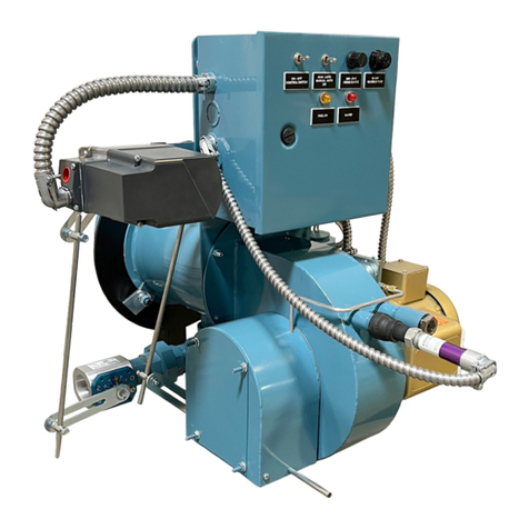
Webster SC Series User guide

Webster Combustion Technology LLC
619 Industrial Road, Wineld, KS 67156
Installation, Startup, Operation and Maintenance Manual
SC Series
Forced Draft Burners
Manual Part No. 950108 - R1
www.webstercombustion.com
August, 2017
2017 All Rights Reserved
C

SAFETY PRECAUTIONS
Page 2 Safety PrecautionsSC Manual
Good safety practices must be used when working on burner equipment. The potential energy in the electrical supply,
fuel and related equipment must be handled with extreme care to prevent equipment failures, injuries and potential
death.
Throughout this manual, the following symbols are used to identify potential problems.
WARNING
This indicates a potential hazardous situation, which if not avoided, could result in personal injury or death.
CAUTION
This indicates a potentially hazardous situation which, if not avoided, could result in damage to the equipment.
The following general safety precautions apply to all equipment work.
WARNING
IF YOU SMELL GAS, OPEN THE WINDOWS, EXTINGUISH ANY OPEN FLAMES, STAY AWAY FROM
ELECTRICAL SWITCHES, EVACUATE THE BUILDING AND IMMEDIATELY CALL THE GAS COMPANY.
IN ACCORDANCE WITH OSHA STANDARDS, ALL EQUIPMENT, MACHINES AND PROCESSES SHALL BE
LOCKED OUT PRIOR TO SERVICING.
IF THIS EQUIPMENT IS NOT INSTALLED, OPERATED AND MAINTAINED IN ACCORDANCE WITH THE
MANUFACTURERS INSTRUCTIONS, THIS PRODUCT COULD EXPOSE YOU TO SUBSTANCES IN FUEL OR
FROM FUEL COMBUSTION WHICH CAN CAUSE DEATH OR SERIOUS ILLNESS AND WHICH ARE KNOWN
TO THE STATE OF CALIFORNIA TO CAUSE CANCER, BIRTH DEFECTS OR OTHER REPRODUCTIVE HARM.
IMPROPER SERVICING OF THIS EQUIPMENT MAY CREATE A POTENTIAL HAZARD TO EQUIPMENT AND
OPERATORS.
SERVICING MUST BE DONE BY FULLY TRAINED AND QUALIFIED PERSONNEL.
BEFORE DISCONNECTING OR OPENING UP A FUEL LINE AND BEFORE CLEANING OR REPLACING
PARTS OF ANY KIND:
• TURN OFF THE MAIN MANUAL FUEL SHUTOFF VALVES INCLUDING THE PILOT COCK, IF
APPLICABLE. IF A MULTIPLE FUEL BURNER, SHUT OFF ALL FUELS.
• TURN OFF ALL ELECTRICAL DISCONNECTS TO THE BURNER AND ANY OTHER EQUIPMENT OR
SYSTEMS ELECTRICALLY INTERLOCKED WITH THE BURNER.
Service Organization Information:
Company Name
Address
Phone Number
Date of Startup
Lead Technician

Safety Precautions ...............................................................................................................................
A. Introduction ..........................................................................................................................................
Burner Model Number..............................................................................................................
SC Specications.....................................................................................................................
SC Model Conguration...........................................................................................................
Specication Data....................................................................................................................
Dimensional Data....................................................................................................................
B. Component ldentication......................................................................................................................
C. Installation.............................................................................................................................................
D. Special lnstructions For Canadian lnstallations....................................................................................
E. Burner Mounting Criteria ......................................................................................................................
F. Fuel Systems........................................................................................................................................
G. Initial Settings.......................................................................................................................................
H. Ignition Systems...................................................................................................................................
I. Start-up & Operating Adjustments........................................................................................................
J. Troubleshooting...................................................................................................................................
K. General Maintenance And Care...........................................................................................................
L. Care of Burner During Shutdown.........................................................................................................
M. Replacement Parts...............................................................................................................................
N. Warranty Validation & Field Start-up Report.........................................................................................
2
3
3
4
5
6
7
8
11
12
13
14
18
19
19
26
28
30
30
30
TABLE OF CONTENTS
A. INTRODUCTION
Page 3 IntroductionSC Manual
This manual covers the Model SC burners offered by
Webster Combustion Technology LLC. These burners can
be used in a wide variety of Cast Iron, Firebox, Firetube,
Flextube and other applications. They can re gas, oil and
combination gas and oil, with several different operating
systems.
READ AND SAVE THESE INSTRUCTIONS FOR
REFERENCE.
WARNING
DO NOT ATTEMPT TO START, ADJUST OR MAIN-
TAIN THIS BURNER WITHOUT PROPER TRAINING
OR EXPERIENCE. FAILURE TO USE KNOWLEDGE-
ABLE TECHNICIANS CAN RESULT IN EQUIPMENT
DAMAGE, PERSONAL INJURY OR DEATH.
The startup and maintenance of the SC burner requires the
skills of an experienced and properly trained burner techni-
cian. Inexperienced individuals should not attempt to start
or adjust this burner.
Every attempt has been made to accurately reect the
burner construction, however, product upgrades and spe-
cial order requirements may result in differences between
the content of this manual and the actual equipment.
These special components will be described in the infor-
mation provided with the burner and should be used as the
controlling document.
NOTE: This manual must be readily available to all op-
erators and maintained in legible condition.
1. Nameplate Information
Each burner has a nameplate with important job details,
similar to the nameplates shown in Figure A-1.
Figure A-1 Nameplate
MODEL NUMBER
SC12C-15-RM7840L-UL-IRI
SERIAL NUMBER
U81375A-018-06
OIL INPUT RATINGGAS INPUT RATING
MBTU/HR IN.WC GPH PSI
2940 2.8 21 300
MAXIMUM
1680 1.0 12 100
MINIMUM
NATURAL GAS #2 FUEL OIL
FUEL
VOLTS AMPS HERTZ PHASE HP
115
CONTROL CIRCUIT 5.0 60 1
208
BURNER MOTOR 5.9 60 31.5
208
OIL PUMP MOTOR 4.3 60 31/2
The serial number represents the unique number for that
burner and is a critical number that will be needed for
any communications with Webster Combustion.
The input rates dene the maximum and minimum inputs
for that burner, given in MBH for gas and GPH for oil.
Air atomized burners show both the oil pressure and
air pressure. Pressure atomized burners only list the oil
pressure. For gas ring, the gas manifold pressure is
given in “in wc” which is inches of water column.
The electrical ratings of the burner are given, with the volt-
age, current load, frequency and phase (this will either
be single or 3-phase). For motors, the motor HP is listed.

2. Ratings
The ratings for each specic burner are given on the
nameplate. The general burner ratings are given in
Specication Sheets that follow this section. The
maximum inputs are given, based on the type of fuel.
Other conditions, like the supply gas pressure or the
combination of fuels, emission requirements and control
systems may prevent the burner from reaching the
lowest ring rate.
3. Product Offering
The SC burner can re natural gas as well as #2 oil.
DO NOT USE GASOLINE, CRANKCASE OIL OR ANY
OIL CONTAINING GASOLINE.
Figure A-2 lists the common variations and options
available on this product. The minimum furnace
conditions are given in Section C.
4. Your Complete Manual
In addition to this manual, there are several other
documents that should be considered as part of the
complete manual for the burner. All of these documents
are needed to support the installation and startup of the
unit. These additional items include:
a. The wiring diagram, which shows the limits and inter
connection of the burner and vessel controls.
b. The gas piping schematics, which show the
components and their positions in the piping train.
c. The unit material list which provides an overview of
the burner requirements and a complete bill of
material, including the part numbers and description
for each item.
d. The ame safeguard manual provides the
operating sequence for the burner management
system. This will be a critical document for trouble-
shooting any future problems.
e. Catalog cuts of the major components. These
provide details on the installation, adjustment and
maintenance of the components used on the burner.
5. Service, Parts and other Information
Service and parts are available from your local Webster
Representative. For a list of Webster Representatives,
please visit the Webster web site at:
www.webster-engineering.com or call 620-221-7464
Page 4 IntroductionSC Manual

SC BURNER MODEL CONFIGURATION
FIGURE A-2
SC12G -50-LMV51-M.25-M-MP-UL/CSD-1
BURNER SERIES
SC SC SERIES
HEAD SIZE (INCHES)
SC
8
10
12
12.3
13
13.8
14
15
15.8
16
18
20
24
FUELS
G Gas
CGas/Oil
O Oil
BLOWER MOTOR
HORSEPOWER
20 2
25 2 1/2
30 3
50 5
75 7 1/2
100 10
150 15
200 20
250 25
300 30
400 40
FLAME SAFEGUARD
VENDOR DESIGNATION
M Mark AutoFlame - mini mark
Nexus Fireye
LMV51 Siemens
LMV52 Siemens
The above represents the common model designations. Contact the factory for other options and special applications.
Page 5 Model CongurationSC Manual
CODES AND
LISTINGS
UL
ULc
CSD-1
FM
IRI
NFPA-85
OIL SYSTEMS
Pressure Atomizing
MR Modulation By-Pass
MP Modulation Simplex
Air or Steam Atomization
MA Air Atomization
MS Steam atomizing
GAS TRAIN VENDOR
VGD Siemens
VGG Siemens
M Maxon
Blank All Others
(ASCO) - (std)
GAS TRAIN SIZE
.15 1 1/2 inches
.20 2 inches
.25 2 1/2 inches
.30 3 inches
.40 4 inches
GAS SYSTEMS
M Modulation

STANDARD UL EQUIPMENT
AND IMPORTANT OPTIONS (1)
STANDARD UL EQUIPMENT
AND IMPORTANT OPTIONS
General
Motor, Fan and Air Inlet Control X X
Gas Fuel
Main Manual Shutoff Valve X
Air Flow Switch (also with oil systems using remote
pump) X XMain Safety Shutoff Valve X
Burner Mounted Control Panel, Switch and Indicator
Lights (2) X X Second Safety Shutoff Valve X
Flame Safety Control X X Main Gas Regulator X
Ultra Violet Scanner X X Gas Checking Valve X
Motor Controller (single phase voltage)
Fuel Selector Switch
High and Low Gas Pressure Switches (st’d
over 2500 MBH) Opt.
Ignition
Proven Gas Pilot Ignition X X
Optional
Inverted Housing
Pilot Solenoid Gas Valve X XAlternate Control Cabinet Positioning
Pilot Gas Regulator & Manual Valve X XRemote Control Panel
Pilot Gas Ignition Transformer X X
Direct Spark Oil Ignition X X
Direct Spark Oil Ignition Transformer X X
1. The conguration of each unit will vary with specic job requirements such as input rating, electrical specication and special agency approval
codes. The above chart shows those items standard to a basic burner plus a few options that may be added.
2. Indicator lights are “Power On”, “Call for Heat”, ”Fuel On” and ”Flame Fail” for hard wired panels. “Alarm”, “Low Water”, “Power”, “Call for
Heat”, “Ignition On”, and “Fuel On” for circuit board light panels.
?. Larger motors may be required for single phase or 208 volts
The above maximum ratings are based on 0 furnace pressure, an altitude of 1000 feet, 90oF air temperature and 60 HZ electrical
supply. Use the following corrections for higher temperatures and altitude. Capacity decreases by 17% for 50 Hertz.
Capacity decreases by 4% for each 1000 feet above 1000 foot altitude.
Capacity decreases by 5% for each 1 inch of furnace pressure.
Capacity decreases by 2% for each 10oF increase in air temperature over 90oF.
Gas input ratings based on 1000 BTU/cu ft. and 0.64 specic gravity. Sizes and pressure will vary with gas.
Essential Ordering Information and Data:
Power Supply - Conrm 120-60-1 for control circuit and electrical supply for burner motor(s) (voltage, frequency and phase).
Describe Boiler or Heater to be Fired - Including the manufacturer, model number, furnace pressure and furnace size.
Firing Rate - Dene ring rates in MBH for gas. Fuel to be Burned - Type of gas, including the BTU value.
Approval Agency - UL, FM, IRI (GE GAP), CSD-1, NFPA, Mil spec and local codes, if applicable.
Flame Safety Control Preferred - Honeywell or Fireye controls.
Gas Train Components Preferred - ASCO/ITT, Honeywell or Landis
Control System - ON-OFF, Low Fire Start, Low-High-Low, Modulation, Posi-Control
Required Options - Mounting plate, limit controls, etc.
Model SC - Specication Data (2,400 MBH - 28,800 MBH Input)
Power Supply: Conrm 120-60-1 for control circuit and electrical supply for burner motor(s) (voltage, frequency and phase).
Describe Boiler or Heater to be Fired: Including the manufacturer, model number, furnace pressure and furnace size. Firing Rate: Dene ring rates
in MBH for gas. Fuel to be Burned: Type of gas and/or oil, including the BTU value. Approval Agency: UL, FM, IRI (GE GAP), CSD-1, NFPA, Mil spec
and local codes, if applicable. Flame Safety Control Preferred: Honeywell, Fireye or Siemens controls. Gas Train Components Preferred: ASCO/
ITT, Honeywell or Landis Control System - Modulation, Posi-Control Required Options - Mounting plate, limiting controls, etc.
Model SC - Specication Data
Page 6 Specication DataSC Manual
Model SC - Specication Data (2,400 MBH - 28,800 MBH Input)
Gas
Oil
Oil
Fuel
X X
(1) STANDARD
EQUIPMENT AND
IMPORTANT OPTIONS
Gas
No. 2 Oil
STANDARD EQUIPMENT
AND IMPORTANT OPTIONS
Gas
No. 2 Oil
Pressure
Atomized
Air
Atomized
Pressure
Atomized
Air
Atomized
General
Motor, Fan and Air Inlet Control X X X
Gas Fuel
Main Manual Shutoff Valve X
Air Flow Switch X X X Main Safety Shutoff Valve X
(2) Burner Mounted Control Panel,
Switch and Four Indicator Lights X X X Second Safety Shutoff Valve X
Main Gas Regulator X
Flame Safety Control X X X Gas Checking Valve X
Ultra Violet Scanner X X X High and Low Gas Pressure Switches X
Motor Starter with Overloads X X X Metering Valve (modulating systems) X
Fuel Selector Switch Dual Fuel Burners
Only
Normal Open Vent Valve (above
12,500 MBH) X
Ignition
Linkageless Control X X X
Oil Fuel
Oil Drawer Assembly with Diffuser X X
Proven Gas Pilot Ignition X X X Oil Nozzles X X
Pilot Solenoid Gas Valve X X X Remote Oil Pump X Opt.
Pilot Gas Regulator & Manual Valve X X X Two Safety Shutoff Valves X X
Options
Pilot Gas Ignition Transformer X X X Low Oil Pressure Switch X X
Inverted Housing X X X Oil Pressure Gauge X X
Alternate Control Cabinet Positioning X X X Oil Metering Valve X X
Remote Control Panel X X X Air Compressor X
1. The conguration of each unit will vary with specic job requirements such as input rating, electrical specication and special agency
approval codes. The above chart shows those items standard to a basic burner plus a few options that may be added.
2. Indicator lights are “Power On”, “Call for Heat”, ”Fuel On” and ”Flame Fail”.
IgnitionOptions

Page 7 Dimensional DataSC Manual
Model SC - Dimensional Data
Fuels Burned and Control Systems
- Natural Gas
- Light #2 Oil, Mechanical Pressure
- Modulating or Micro Modulation
- Control Circuit Requires 120 vac, 60 Hz, Single Phase Voltage Supply
Model SC burners can be packaged to meet specic requirements of IRI, FM, GE GAP, NFPA, MIL spec. or other
special insurance or local code requirements.
(Dimensions are +/- 1/4 inch)

B. COMPONENT IDENTIFICATION
Page 8 IdenticationSC Manual
Control
Cabinet
Louver Box
This secion shows the different common components used in the SC burner line and should be helpful to identify
parts described elsewhere in this manual.
Oil Pressure Switch
Oil Pressure Gauge
Oil Lines
Air Pressure Switch
Pilot Gas
Regulator
Secondary Fuel
Mod Motor
Figure B-1
SC Dual Fuel
Burners
Primary Fuel
Buttery
Combustion Head
Oil Pressure
Gauge
Figure B-2
SC Burner Side View
Control
Transformer
IgnitionTransformer Blower Motor
Secondary
Fuel Supply
Primary
Fuel Supply
Gas Separator Solenoid Valve

Page 9 IdenticationSC Manual
Oil Nozzles
Spark Plug
Secondary Gas Orices
Primary Gas Orices
Diffuser Assembly
Figure B-3
SC Head
UV Sight Port
Figure B-4
Control Panel
Hard Wired Design
Figure B-5
Air Compressor
Pressure Gauge
Air Filter
Compressor
Air Chamber
Belt Guard
Electric
Motor
Air Discharge
Connection
Terminal Strip
BMS Display
Burner Management
System
Burner Motor
Starter
Control Relays
Switch / Light Panel

Page 10 Identication
SC Manual
Gas Orice Part Number and Description
SECONDARY
AIR SLOTS
ACCESS COVER
OIL SUPPLY LINE
OIL NOZZLE
CHECK VALVE
SECONDARY GAS CONNECTION
PRIMARY GAS CONNECTION
HOUSING MTG. FLANGE
SECONDARY ORIFICE PLATE
MOUNTING FLANGE
OUTER CYLINDER
PRIMARY
ORIFICE PLATE
SECONDARY ORIFICE TUBES
PRIMARY
GAS MANIFOLD
GAS TUBE
IGNITION HOLDER
INNER CYLINDER
SECONDARY GAS MANIFOLD
ON VESSEL INSERTION DEPTH
DIMENSION WILL VARY DEPENDING
Figure B-8
Drawer Assembly

Page 11 InstallationSC Manual
C. INSTALLATION
Prior to installing the burner, the site conditions and
utilities need to be evalulated. This section provides
some general questions that can help the review pro-
cess. Inspect the burner for any undetected damage
that may have occurred during shipment or by job-site
handling. Special attention should be given to the
control panel and protruding parts. Check wiring
connections and fasteners for tightness.
Verify that all ship loose (or separately shipped) items
are on hand. This normally will be gas train compo-
nents, mounting lugs and insulating rope. Also, front
mounting plate and remote oil pump set, if supplied.
The burner material list included with the instruction
manual serves as a good checklist for this purpose.
1. Is there adequate outside ventilation to supply the
needed air for safe combustion as required by your
local regulatory agency?
2. If a burner mounting plate is required, is it available
and does it meet specications? (See Section E)
3. Is the correct voltage available for the control circuit
and is the correct voltage available for the blower motor
as well for the remote oil pump set and air compressor,
if used?
4. Will the burner properly t the boiler or heater with
ample clearance on top, bottom and sides?
5. If a gas burner, will there be adequate gas pressure
to assure the specied ring rate?
6. If a combination burner, is gas available at the
burner location?
7. If a combination burner, what is the age and condition
of the oil tank(s) and will there be special piping
arrangements needed to deliver the oil to the burner?
Important Note: The SC series burners must be
operated with a two-pipe system.
8. If a retrot installation, has the same oil grade always
been used? Does it meet the grade specied on the
burner’s rating plate?
CAUTION
THE COMBINATION BURNER SHALL ONLY BURN
THAT GRADE OF OIL SHOWN ON THE RATING
PLATE. DO NOT USE GASOLINE, CRANKCASE
OIL, OR ANY OIL CONTAINING GASOLINE OR
TOXIC CONTAMINANTS.
9. Is there adequate ue provisions to assure SAFE and
proper venting of the burner?
10. All manuals should be reviewed and understood and
stored in a convenient place.
11. Teon tape should not be used on any eld piping.
12. Rope gaskets should be used between vessel and
mounting plate, and between mounting plate and burner.
13. Gas piping should be ushed (cleaned) prior to use.
14. Check minimum straight lengths for gas pressure
regulator and/or sensing line.
15. Oil piping to be ushed (cleaned) prior to use.
16. Check pump suction pressure (max 10” Hg) or max
press (3 psig) if transfer pump is used or tank elevation is
higher than the pump.
17. Strainer before oil pump, sized for max pump suction
capacity.
18. If multiple vessels connect to a single stack, are they
sized and designed to maintain +/- 0.1” wc draft at the
vessel outlet under all operating conditions.
19. Is stack designed to maintain +/- 0.1” wc at outlet
during all operating conditions.
WARNING
DO NOT USE TEFLON TAPE OR COMPOUNDS
CONTAINING TEFLON. THIS COULD DAMAGE THE
VALVES CREATING AN UNSAFE OPERATION
20. Is the burner mounting plate and burner head sealed
with rope gasket? (See Figure E-2)
21. Is there a drip leg in the gas supply to capture foreign
material? (See Figure C-1)
22. Is the piping between the gas train and burner done in
a manner that will minimize the pressure drop?
23. Has all of the piping been pressure checked for leaks?
24. Is the combustion chamber of proper size and is the
center-line height of the burner head adequate? (See
charts C-2 & C-3.)

Page 12 Installation/Canadian InstallationsSC Manual
D. SPECIAL INSTRUCTIONS FOR CANADIAN INSTALLATIONS
1. The installation of a burner shall be in accordance with
the regulations of the provincial installation requirements,
or in their absence, the following shall govern:
Gas Burners--CGAB149.1 and CGAB149.2
Authorities having jurisdiction should be consulted before
installations are made.
2. All electrical wiring shall be done in accordance with
the Canadian Electrical Code, Part I.
3. The installer shall identify (label) the main electrical
power disconnect and the manual shut-off valve on the
gas and/or oil supply drop-line to the burner.
4. Oil and gas burning equipment shall be connected to
ues having sufcient draft at all times, to assure safe and
proper operation of the burner, no more than -0.25 iwc.
Chart C-2 Chart C-3
TYPICAL COMBUSTION CHAMBER SIZE
FOR FIREBOX BOILERS, WATERTUBE &
CAST IRON SECTIONAL TYPES
TYPICAL COMBUSTION CHAMBER SIZE
FOR SCOTCH MARINE FIRETUBE BOILERS
PILOT SHUTOFF
VALVE
GAS SUPPLY
DRIP LEG
PILOT LINE
(FIELD PIPED)
PILOT GAS PRESSURE
REGULATOR
PILOT SOLENOID VALVE
GAS PRESSURE
REGULATOR
SHUTOFF VALVE SHUTOFF VALVE
LEAK TEST
VALVE
HIGH PRESSURE
SWITCH
BURNER
IF APPLICABLE,
WEBSTER-SUPPLIED
GAS TRAIN
LOW PRESSURE
SWITCH
MANUAL GAS
SHUTOFF
VALVE
Figure C-1
Typical Gas Piping

Page 13 Burner Mounting CriteriaSC Manual
E. BURNER MOUNTING CRITERIA
It is of vital importance that the burner be properly mounted to the boiler or appliance being red. Improper mounting
can cause leakage of the hot gases back around the burner head resulting in warpage and deterioration. The follow-
ing illustrations show the proper way the burner must be installed to validate warranty conditions.
A
B
TYPICAL SC BURNER REFRACTORY FRONTPLATE Dimensions - Inches
MODEL DIM. A DIM. B
SC8 9.25” 14.00”
SC10 11.25” 16.00”
SC12 13.25” 17.00”
SC12.3 13.56” 19.00”
SC13 15.00” 19.00”
SC13.8 15.00” 19.00”
SC14 15.25” 19.00”
SC15 17.00” 20.50”
SC15.8 17.00” 20.50”
SC16 17.25” 20.50”
SC18 19.25” 22.50”
SC20 21.25” 24.50”
SC24 25.25” 28.50”
Figure E-1
Refractory Dimension
Contact Webster for more detailed
refractory drawings.
Figure E-2
Burner Mounting Instruction
BURNER MUST
BE LEVEL
REFRACTORY
FRONT PLATE
IF GAP IS OVER 3/16”
WRAP BURNER NOSE WITH
HIGH TEMPERATURE
CERAMIC INSULATION ROPE
FILL VOIDS BETWEEN FRONT
PLATE AND VESSEL WITH
CERAMIC BLANKET 4” DEEP
OR AS DEFINED BY VESSEL
MANUFACTURER
THIS SURFACE MUST
BE SEALED AGAINST
THE VESSEL. CHECK
VESSEL MOUNTING
REQUIREMENTS.
THIS SURFACE
MUST BE SEALED
AGAINST THE
VESSEL. CHECK VESSEL
MOUNTING
REQUIREMENTS.
ATTACHMENT TO VESSEL VARIES WITH MANUFACTURE.
(FOLLOW VESSEL MANUFACTURER’S RECOMMENDATION)
THE GAS PIPING FROM THE BURNER TO THE
TRAIN SHOULD HAVE AS FEW ELBOWS AS
POSSIBLE TO REDUCE PRESSURE DROP.

Page 14 Fuel SystemsSC Manual
F. FUEL SYSTEMS
The SC burner can be equipped with a wide range of fuel and operating systems to control the fuel, air, modulation
and pilots. This section describes how these systems operate. Burner start-up is expected to be done by service per-
sonnel who are qualied in the basics of mechanical know-how. The following illustrations and information is supplied
to identify the various fuel; air and ignition devices that have Adjustment Features. All adjustments can be done with
common place tools normally carried by burner and boiler service personnel.
NOTE
Refer to the bulletins included in the manufacturer’s data section of the burner instructions manual for items below.
1. Pressure atomized oil systems
Field Piped
Suction
Supply Line
Check
Valve
Shutoff
Valve Strainer
Check
Valve
By Others
Return to Tank,
(No Manual
Valves in this
Line)
Oil Metering
Valve
1
1
1
Low Oil
Pressure Switch
2
Main Oil
Solenoid Valve
Safety Oil
Solenoid Valve
Oil Nozzle
Gauge Port
Adjustment
Oil Pump
By Others
(Unless Specied on Order)
Notes & Options
These Lines are Field
Piped if a Remote Pump
is Used
Usage Requirement
Varies with Code
2
1
“MP” - Modulating Simplex Nozzle
Strainer
Back Pressure
Reg. Valve
Low Oil
Press. Sw.
Pressure
Gauge Main Oil
Solenoid Valve
Safety Oil
Solenoid Valve
2
Oil Nozzle
(Bypassing)
Inline
Check
Valve
Gauge Port
Oil Pump
Check
Valve
Shutoff
Valve
Suction
Supply Line
Check
Valve
Field Piped
Return to Tank
(No Manual
Valves in this Line
By Others
(Unless Specied in Order) Pressure
Gauge
Oil Metering
Valve
Check
Valve
1
1
1
Notes & Options
These Lines are
Field Piped if a
Remote Pump is
Used
Required Above 20
GPH if a Remote
Pump is Used
1
2
“MR” - Modulating Return
Flow Nozzles

Page 15 Fuel SystemsSC Manual
Pressure
Reducing
Valve
300 lb.
Gauge
Steam
Syphon
Ball or Gate
Valve Steam
Strainer
125 PSIG
Max.
Atomizing
Steam
Condensate
Return
Steam
Trap
Ball or Gate
Valve
Field Piped
Drip Leg
Metering Lever
Ball Valve Linked
to Mod. Motor
N.C
Atomizing
Valve
Low Atomizing
Pressure Switch
Steam
Syphon
Check
Valve
Steam
Syphon
Gauge
“MA” or “MS” - Modulating House Air or Steam
NOTE: House air does not use steam Syphon or Steam Trap
2. Air Atomized Oil Systems
Field Piped
Compressor
Safety
Valve
Air Filter
Ball Valve
(man. set to adjust air
volume & high re air
pressure)
Pressure
Gauge
Low
Atomizing
Pressure
Air pipe same size
as discharge open-
ing in air chamber
(eld Piped) Check
Valve
Gauge Nozzle
Ball
Valve
Oil
Gauge Flexible Metal Hoses or
Copper Tubing
N.C.
Main Oil
Valve
Safety
Oil
Valve
Oil
Metering
Valve
Gauge
Low Oil
Pressure
Relief
Valve
Ball or
Gate
Valve
Compound
Gauge
Gauge
Check
Valve Return
to Tank
Oil
Suction
Check
Valve
Gate
Valve
Strainer
“MA” - Modulating #2 Oil
Field Piped
Air
Chamber

Page 16 Fuel SystemsSC Manual
2. Gas Systems
Illustrated Gas Trains by Capacity and Code: The following illustrations show the Webster conguration for
UL, FM and IRI as grouped by UL capacity ratings. Refer to the legend below for component part identication.
These illustrations are not to be used for eld erection and/or system design purposes.
UL-FM Modulation Gas Piping Diagram - Up To 2,500 MBH Firing Rate
722166
To 2,500,000 Modulating
Modulating
Modulating
Modulating
Modulating
Modulating
Modulating
M
M
M
M
M
M
M
722166
722167
722168
722169
722170
722171
722172
X
X
X
X
X
X
X
UL Modulation Gas Piping Diagram - 2,500 To 5,000 MBH Firing Rate
722167
UL Capacity Range
BTU/Hr.
Operation Mode Webster
Designation
Code Illustration
UL FM
2,500,001
to 5,000,000
X
5,000,001
to 12,500,000
12,500,001
and Up

Page 17 Fuel SystemsSC Manual
FM Modulation Gas Piping Diagram - 2,500 To 5,000 MBH Firing Rate
722168
UL Modulation Gas Piping Diagram - 5,000 To 12,500 MBH Firing Rate
722169
FM Modulation Gas Piping Diagram - 5,000 To 12,500 MBH Firing Rate
722170
UL Modulation Gas Piping Diagram - Over 12,500 MBH Firing Rate
722171

Page 18 Initial SettingsSC Manual
G. INITIAL SETTINGS
The burner will be set at the factory for normal initial settings. These are only rough settings that must be adjusted at
startup to match the furnace, fuel pressure and environment of the specic application. These general settings are
covered in this chapter as a means of checking the burner or readjusting the burner if the settings are lost. Presets
can change during shipping.
COMBUSTION AIR CONTROL
Panel
Adjusting
Screw
Air Proving
Switch
Air Flow Interlocking Switch
1. OIL NOZZLE POSITION
The oil nozzle will be adjusted at start-up and may be
moved in or out from this initial setting.
2. AIR PROVING SWITCH
The air proving switch has been adjusted at the
factory for an initial setting. If the switch trips during
initial start-up, turn the adjustment screw CCW two
full turns to reduce the trip pressure setting.
CAUTION
ACTUATOR MOUNTINGS CAN BE BENT OR MOVED DURING SHIPMENT AND
INSTALLATION. THEY MUST BE CHECKED PRIOR TO OPERATION AND ANY FAULTS
CORRECTED. FAILURE TO CORRECT A MISALIGNED CONTROL WILL RESULT IN
PREMATURE FAILURE.
FM Modulation Gas Piping Diagram - Over 12,500 MBH Firing Rate
722172

Page 19 Ignition Systems/ Startup and Operating Adjustments
SC Manual
H. IGNITION SYSTEM
1. Pilot
A crucial part of reliable burner operation is a dependable
pilot. The way the SC burner operates is that the primary
zone is lit rst, thus acting as a pilot, before the secondary
fuel valve is opened and the burner can operate the entire
operating range.
The spark plug position can be seen in gure H-1.
Pilot gas pressure should be measured at the 1/8” port
located downstream of the primary solenoid valve.
2. Air Damper Position
The air damper should be near close at low re and close
to full open at high re.
3. Gas Modulating Control Valve Position
The gas valve should be open about 10% at low re and
stroked at least 60% open at high re.
4. Oil Modulating Control Valve Position
For pressure atomizing, the low re position should be
adjusted to get the correct low re pressure, as stated on
the rating label. Typically, this would be 100 psi for simplex
systems and 65 psi for return ow nozzles. The high re
position should be about 45º to 60º travel from low re. For
air atomizing, the low re should be on about #2 position
and the high re should be about the #8 position.
Spark
Plug
I. STARTUP AND OPERATING ADJUSTMENTS
1. Pre-Start Check List
2. Burner Drawer Adjustments
3. Gas Setup
4. Pressure Atomized Oil Setup
5. Air Atomized, #2 Oil Setup
6. Operating Control Adjustments
7. Limit Tests
8. Pilot Test
9. Burner Shutdown
10. Restarting After Extended Shutdown
This section covers the startup and operating adjustments
of the Webster Models.
WARNING
BURNER STARTUP, COMBUSTION ADJUSTMENTS
AND LIMIT CONTROL ADJUSTMENTS SHOULD BE
PERFORMED ONLY BY TRAINED, EXPERIENCED
SERVICE TECHNICIANS. ATTEMPTING TO PER-
FORM THESE FUNCTIONS WITHOUT THE PROPER
TRAINING CAN RESULT IN EQUIPMENT DAMAGE,
PERSONAL INJURY OR DEATH.
operating and installation manual, as well as all control
manuals to verify that equipment is ready for operation.
These manuals must be read prior to start of equipment.
If you are not qualied to service this equipment, DO
NOT TAMPER WITH THE UNIT OR CONTROLS -
CALL YOUR SERVICEMAN.
A block diagram of the startup sequence for the SC
burner can be found on page 25, Figure I-3.
When nished with startup, document valve and linkage
positions, pressures, and settings for future reference.
READ AND SAVE THESE INSTRUCTIONS.
Figure H-1
During purge, all solenoids, including the gas separator
solenoid valve, are closed and are to remain closed until
called upon. After purging the system for at least
30 seconds, the spark plug is activated. Waiting for one
second for the spark to initiate, the pilot solenoid valve
is opened which will ignite the primary zone. When
the ame safeguard system detects a strong signal, it
will open the main fuel valve to start the ignition of the
secondary zone. Following a 4-second delay, the gas
separator solenoid valve will open and the pilot solenoid
can be closed. From this point on, the burner can be
driven to low re.
Before proceeding with startup and adjustment, be sure
that overall installation is complete. Review the boiler
Every burner set-up is different, therefore the positions
below are indications only and tuning must be done by
fully trained and qualied personnel.

Page 20 Startup and Operating Adjustments
SC Manual
1. Pre-Start Check List
Before starting the burner, a complete review of the
installation, wiring and piping of the burner, boiler and all
supporting equipment must be complete and all of these
items must be ready for operation prior to starting. The
following is a general review:
______ All wiring is connected. Gently pull on all the
wires to make sure that they are connected
properly.
______ All fuel lines are connected and tight.
______ Pilot gas is connected.
______ Burner is mounted to vessel and oor, with all
bolts secured.
______ The stack is connected and routed to the outside.
Draft controls are installed and operational, if
needed.
______ Gas vent lines are connected and routed to the
outside, if required per code.
______ Do not start the unit unless all cleanout doors are
in place and secured.
______ The vessel is completely installed, lled with
water and operating controls checked.
______ Support equipment is in place and ready (feed
pumps, draft controls, steam/hot water systems,
boiler limits and controls and feedwater systems).
______ A load must be available for the burner startup
and adjustment process. The burner must be
operated at high rates for extended periods
and the load must be able to use this energy.
______ A combustion analyzer with O2 and CO (for gas)
must be available to tune combustion. A smoke
spot tester must be available for oil ring. A NOx
analyzer must be available. All of these analyzers
must be recently calibrated and able to provide
accurate readings.
______ Other test equipment, including manometers,
gauges and volt meter shall be available.
______ Manometer or gauge on the gas manifold.
______ Manometer or gauge before and after gas
pressure regulator.
______ Draft gauge or manometer (at stack outlet).
______ Draft gauge or manometer for furnace pressure.
2. Burner Drawer Adjustments
The burner drawer has several adjustments built into the
design that allow the combustion to be tuned. While this
can simplify the combustion tuning process, care must be
used to retain the relative position of other components
during this sequence. If these adjustments are required,
follow the sequence listed to perform the adjustments.
The burner drawer must be removed for access to
components, follow the following steps:
a. Loosen and remove the screws on the burner
drawer.
b. Disconnect the scanner by screwing it off of the
scanner tube. In some cases, the scanner simply
pulls out, with a spring tension. Secure the scanner
so that it is protected from shock.
c. Pull the drawer out, holding it centered in the
opening to prevent it from hanging up while being
pulled.
d. Set the drawer down horizontally.
To re-install the burner drawer, simply work the
procedure in reverse.
3. Gas Setup
a. Place the burner switch in the “OFF” position
b. Place the burner management system in manual
mode”. If this is a combination fuel burner, make
sure the fuel selector switch is on “GAS”.
c. Place the burner management system in the low
re position.
d. Close the downstream manual shutoff valve
(closest to the burner head) on the gas train.
e. Turn the electrical power on for the burner, boiler
and related components.
f. Verify that the gas metering valve is nearly closed,
the vent valve (if equipped) is operating and the gas
pilot valve is not open (the solenoid will hum and
feel warm).
g. Turn the burner switch on. This will start the blower
motor and initiate the prepurge cycle.
h. When the prepurge sequence is complete and the
low re start switch is made, the ame safeguard
should indicate the presence of a ame.
i. When the pilot ame is established, the ame
safeguard will energize the main gas valve
(indicated with the Fuel Valve Light). This operation
of the main fuel valves must be visually checked by
observing the valve stem operation.
j. After the timer has completed the trial for main
ame, the burner will go out on alarm (the closed
manual gas valve prevented the burner from
lighting). At this time, the gas valves must be
visually checked to verify that they have closed.
This test sequence proves the proper operation of
the primary control.
k. Press the reset button and restart the burner. When
the pilot has started, open the manual gas valve to
allow the main ame to start.
l. After a few seconds, the combustion analyzer
should have an accurate reading of the O2in the
stack. Fig. I-1 shows the typical range of O2at
different ring rates, and the burner should be
adjusted to be within this range. Rough settings for
low and mid re combustion settings are adequate
at this time. Once the high re is set, the other
settings can be ne tuned.
This manual suits for next models
13
Table of contents
Other Webster Burner manuals
Popular Burner manuals by other brands

Riello
Riello RLS 160/E Installation, use and maintenance instructions

LAMBORGHINI
LAMBORGHINI ECO 3C Series Installation - use - maintenance

Riello
Riello RS 190/M Installation, use and maintenance instructions

Weishaupt
Weishaupt WL30Z-C 4LN manual

Pit Boss
Pit Boss PB5BGD1 manual

Planika
Planika Forma 1200 Front installation manual

Riello
Riello RLS 68/M MX FS1 Installation, use and maintenance instructions

Riello
Riello RS 310/M BLU Installation, use and maintenance instructions

baltur
baltur Minicomist 7 manual

elco
elco VECTRON G 1.40 operating instructions

Coleman
Coleman FYRESTORM Instructions for use

Enertech
Enertech B20KAV Installation and maintenance instruction