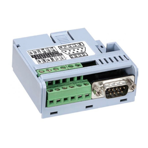
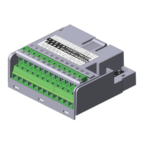
WEG DeviceNet CFW500 Quick guide

CAN Communication
Plug-in Module
Módulo Plug-in de
Comunicación CAN
Módulo Plug-in de
Comunicação CAN
CFW500
Installation, Configuration and Operation Guide
Guía de Instalación, Configuración y Operación
Guia de Instalação, Configuração e Operação
Motors | Automation | Energy | Transmission & Distribution | Coatings


Summary / Índice
English
EspañolPortuguês
SUMMARY
1 SAFETY INFORMATION...............................5
1.1 SAFETY WARNINGS ....................................5
1.2 PRELIMINARY RECOMMENDATIONS.......5
2 GENERAL INFORMATION...........................5
3 CONTENTS OF THE PACKAGE...................6
4 ACCESSORY INSTALLATION .....................6
5 CONFIGURATION.........................................7
APPENDIX A – FIGURES...............................23
ÍNDICE
1 INFORMACIONES DE SEGURIDAD .........11
1.1 AVISOS DE SEGURIDAD ........................... 11
1.2 RECOMENDACIONES PRELIMINARES... 11
2 INFORMACIONES GENERALES...............11
3 CONTENIDO DEL EMBALAJE ..................12
4 INSTALACIÓN DEL ACCESORIO..............12
5 CONFIGURACIONES..................................13
ANEXO A – FIGURAS.....................................23
ÍNDICE
1 INFORMAÇÕES DE SEGURANÇA............17
1.1 AVISOS DE SEGURANÇA ..........................17
1.2 RECOMENDAÇÕES PRELIMINARES.......17
2 INFORMAÇÕES GERAIS ...........................17
3 CONTEÚDO DA EMBALAGEM..................18
4 INSTALAÇÃO DO ACESSÓRIO .................18
5 CONFIGURAÇÕES......................................19
ANEXO A – FIGURAS.....................................23


CAN Communication Plug-in Module
English
CFW500 | 5
1 SAFETY INFORMATION
1.1 SAFETY WARNINGS
NOTE!
This guide contains important information
for the correct understanding and
proper operation of the CFW500-CCAN
Comunication Plug-in Module.
Only use the CFW500-CCAN Comunication
Plug-in Module in CFW500 WEG inverters.
We recommend reading the CFW500
user’s manual before installing or operating
this accessory.
1.2 PRELIMINARY RECOMMENDATIONS
ATTENTION!
Always disconnect the general power
supply before connecting or disconnecting
the accessories of the frequency inverter
CFW500.
Wait at least 10 minutes to guarantee
complete de-energization of the inverter.
2 GENERAL INFORMATION
This guide shows how to install, configure and operate
the CFW500-CCAN Communication Plug-in Module.
This plug-in is used in to CFW500 Controller Area
Network (CAN) communications, for further information
about this refer to the CFW500 "CANopen user's
manual" and "DeviceNet user's manual" in the CD-ROM.

CAN Communication Plug-in Module
English
6 | CFW500
3 CONTENTS OF THE PACKAGE
When receiving the product, check if this package
contains:
Accessory in anti-static packaging.
Installation, configuration and operation guide.
4 ACCESSORY INSTALLATION
The accessory is easily installed or replaced. For correct
installation of the accessory execute the following steps:
Step 1: With the inverter without power, remove the front
cover of the inverter (figure A.1 (a)).
Step 2: Remove, if there, the old plug-in module as
in figure A.1 (a).
Step 3: Fit and press the plug-in to be installed as
indicated in figure A.1 (b) and then connect the front
cover of the inverter.
Step 4: Energize the inverter and check if the parameter
P0027 indicates the number 6 (P0027=6). If this information
is not true or the display of the HMI won’t turn on, check
if the module used is actually the CFW500-CCAN, and
repeat steps 1-4.

CAN Communication Plug-in Module
English
CFW500 | 7
5 CONFIGURATION
The control connections (analog input / output, digital
inputs / outputs and RS485 interface) must be performed
in the connector as in figure 1.
RS485 - B
GND
GND
AI1
+10 V
AO1 rpm
≥5kΩ
RS485 - A
DO1-RL-NO
DO1-RL-C
DO2-TR
+24 V
DI1
DI2
R
DO1-RL-NC
Connector Description
Superior Terminal
1DI1 Digital input 1
3DI2 Digital input l 2
5+24 V +24 Vdc power supply
7DO2-TR Digital output 2 (Transistor)
9DO1-RL-NO Digital output 1
(NO Contact of Relay 1)
11 DO1-RL-C Digital output 1
(Common point of Relay 1)
13 DO1-RL-NC Digital output 1
(NC Contact of Relay 1)
Inferior Terminal
2AO1 Analog output 1
4GND Reference (0 V)
6AI1 Analog input 1
8 +10 V Reference (+ 10 Vdc) for potentiometer
10 RS485 - A RS485 (terminal A)
12 RS485 - B RS485 (terminal B)
14 GND Reference (0 V)
Figure 1: Signals of connector

CAN Communication Plug-in Module
English
8 | CFW500
The location of the DIP-switches for selecting the
type of analog input and output signal and RS485 line
termination can be better visualized in figure A.2. To use
the analog inputs and/ or outputs with signals in current,
adjust switch S1 and the related parameters according to
table 1. For further details about the control connections
refer to Chapter 3 - Installation and Connection of
CFW500 user's manual.
Table 1: Settings of switches to select the type of analog
input and output signal of the CFW500-CCAN
Input /
Output Signal Setting of
Switch S1
Range of
Signal
Parameters
Setting
AI1
Voltage S1.1 = OFF 0...10 V P0233 = 0 or 2
Current S1.1 = ON 0...20 mA P0233 = 0 or 2
4...20 mA P0233 = 1 or 3
AO1
Voltage S1.2 = ON 0...10 V P0253 = 0 or 3
Current S1.2 = OFF 0...20 mA P0253 = 1 or 4
4...20 mA P0253 = 2 or 5
NOTE!
Settings for connection of the RS485:
S1.3 = ON and S1.4 = ON: termination
RS485 ON
S1.3 = OFF and S1.4 = OFF: termination
RS485 OFF
Any other combination of switches is not
allowed.
The CFW500-CCAN Comunication Plug-in Module has
a 5-way plug-in connector for CAN communication with
the following features:
Allows communication CANopen and DeviceNet
in the product.
Galvanically isolated interface fron main power
supply with a differential signal, giving greater
resistance against electromagnetic interference.
allows connection of up to 64 devices on the
same segment. A larger number of devices can be
connected using repeaters. The maximum number
of devices that can be plugged into the network also
depends on the protocol used.
Maximum bus length of 1000 meters.

CAN Communication Plug-in Module
English
CFW500 | 9
An external power supply between pins 1 and 5
(figure 2) of the network connector is necessary.
Data for individual consumption and input voltage
are presented in table 2.
The indication of alarms, faults and communication
status is done through the HMI and product
parameters.
Connector Description
1V- Negative pole of power supply
2CAN_L Signal of CAN_L communication
3Shield Cable shield
4CAN_H Signal of CAN_H communication
5V+ Positive pole of power supply
Figure 2: Connector pins for CAN interface
Table 2: Features of the power supply for CAN interface
Power Suply (Vdc)
Minimum Maximum Recommended
11 30 24
Current (mA)
Typical Maximum
30 50
NOTE!
We recommend grounding the GND pin
of the CFW500-CCAN Communication
Plug-in Module (pin 4 or 14).This grounding
is necessary for the cable shield to have a
connection to the ground wire.

CAN Communication Plug-in Module
English
10 | CFW500
To connect the CFW500 frequency inverter using this
module, the following points must be observed:
It is recommended to use specific cables for
CANopen networks.
Grounding the cable mesh in only one site, thus
avoiding current loops. This point is often the source
of mains power. If more than one power supply
is used, only one of them must be connected to
ground protection.
Install termination resistors only at the ends of the
main bus, even if there are derivations.
The power supply network must be capable of
supplying current to operate all the equipment
transceivers. The CFW500 CANopen module
consumes approximately 50 mA.
For further details on the installation of network,
CANopen, DeviceNet and communication see in there
CD-ROM, the manual user's, respectively.
This module has a connector (figure A.2) to enable the
use of the CFW500-MMF Flash Memory Module , which
allows data transfer between inverters. For further details
on this accessory, refer to the installation and operation
guide of the CFW500-MMF.

Módulo Plug-in de Comunicación CAN
CFW500 | 11
Español
1 INFORMACIONES DE SEGURIDAD
1.1 AVISOS DE SEGURIDAD
¡NOTA!
El contenido de esta guía provee
informaciones importantes para el correcto
entendimiento y buen funcionamiento
de el Módulo Plug-in de Comunicación
CFW500-CCAN.
Solamente utilizar el Módulo Plug-in de
comunicación CFW500 -CCAN en los
inversores WEG línea CFW500.
Se recomienda la lectura del manual del
usuario del CFW500 antes de instalar u
operar este accesorio.
1.2 RECOMENDACIONES PRELIMINARES
¡ATENCIÓN!
Siempre desconecte la alimentación
general antes de conectar o desconectar
los accesorios del convertidor de
frecuencia CFW500.
Aguarde por lo menos 10 minutos para
garantizar la desenergización completa
del inversor.
2 INFORMACIONES GENERALES
Esta guía orienta en la instalación, configuración
y operación del Módulo Plug-in de Comunicación
CFW500-CCAN. Este plug-in es usado en
la comunicación CAN (Controller Area Network)
del CFW500. Para más informaciones consulte el
"manual de comunicación CANopen" y el "manual de
comunicación DeviceNet" del CFW500 en el CD-ROM.

Módulo Plug-in de Comunicación CAN
12 | CFW500
Español
3 CONTENIDO DEL EMBALAJE
Al recibir el producto, verifique si el embalaje contiene:
Accesorio en embalaje antiestático.
Guía de instalación, configuración y operación.
4 INSTALACIÓN DEL ACCESORIO
El accesorio es fácilmente instalado o sustituido. Para
la correcta instalación del accesorio ejecute los pasos
a seguir:
Paso 1: Con el convertidor desenergizado, retire la tapa
frontal del convertidor (figure A.1 (a)).
Paso 2: Retire, si existe, el antigo módulo plug-in
conforme la figure A.1 (a).
Paso 3: Encaje y presione el plug-in a ser instalado
conforme indicado en la figura A.1 (b) y luego conecte
la tapa frontal del convertidor.
Paso 4: Energice el convertidor y verifique si el
parámetro P0027 indica el valor 6 (P0027=6). En caso
que esa información no sea verdadera, verifique si el
módulo utilizado realmente es el CFW500-CCAN y
repita los pasos 1-4.

Módulo Plug-in de Comunicación CAN
CFW500 | 13
Español
5 CONFIGURACIONES
Las conexiones de control (entrada/salida analógica,
entradas/salidas digitales e interfaz RS485) deben ser
hechas en el conector conforme figura 1.
RS485 - B
GND
GND
AI1
+10 V
AO1 rpm
≥5kΩ
RS485 - A
DO1-RL-NO
DO1-RL-C
DO2-TR
+24 V
DI1
DI2
R
DO1-RL-NC
Conector Descripción
Borne Superior
1DI1 Entrada digital 1
3DI2 Entrada digital 2
5+24 V Fuente +24 Vcc
7DO2-TR Salida digital 2 (transistor)
9DO1-RL-NO Salida digital 1
(Contacto NA del relé 1)
11 DO1-RL-C Salida digital 1
(Punto común del relé 1)
13 DO1-RL-NC Salida digital 1
(Contacto NF del relé 1)
Borne Inferior
2AO1 Salida analógica 1
4GND Referencia 0 V
6AI1 Entrada analógica 1
8 +10 V Referencia +10 Vcc para potenciómetro
10 RS485 - A RS485 (terminal A)
12 RS485 - B RS485 (terminal B)
14 GND Referencia 0 V
Figura 1: Señales del conector de control

Módulo Plug-in de Comunicación CAN
14 | CFW500
Español
La localización de las DIP-switches para selección
del tipo de señal de la entrada y salida analógica y
de la terminación de la red RS485 pueden ser mejor
visualizadas en la figura A.2. Para utilizar las entradas y/o
salidas analógicas con señal en corriente se debe ajustar
la llave S1 y los parámetros relacionados conforme tabla
1. Para más detalles sobre las conexiones de control
consulte el capítulo 3 - Instalacion y Conexión del manual
del usuario del CFW500.
Tabla 1: Configuraciones de las llaves para selección
del tipo de señal en la entrada y salida analógica en el
CFW500-CCAN
Entrada/
Salida Señal Ajuste de
la Llave S1
Rango de
la Señal
Ajuste de
Parámetros
AI1
Tensión S1.1 = OFF 0...10 V P0233 = 0 a 2
Corriente S1.1 = ON
0...20 mA P0233 = 0 a 2
4...20 mA P0233 = 1 a 3
AO1
Tensión S1.2 = ON 0...10 V P0253 = 0 a 3
Corriente S1.2 = OFF
0...20 mA P0253 = 1 a 4
4...20 mA P0253 = 2 a 5
¡NOTA!
Configuraciones para conexión de la RS485:
S1.3 = ON y S1.4 = ON: terminación RS485
encendida
S1.3 = OFF y S1.4 = OFF: terminación
RS485 apagada
Cualquier otra combinación de las llaves no
es permitida
El Módulo Plug-in de Comunicación CFW500-CCAN
posee un conector plug-in de 5 vías para comunicación
CAN con las siguientes características:
Posibilita la comunicación CANopen y DeviceNet
en el producto.
Posee interfaz de fuente de alimentación principal
aislada galvánicamente y con señal diferencial,
otorgando mayor robustez contra interferencia
electromagnética.
Permite la conexión de hasta 64 dispositivos
en el mismo segmento. Una cantidad mayor de
dispositivos puede ser conectada con el uso de

Módulo Plug-in de Comunicación CAN
CFW500 | 15
Español
repetidores. El número límite de equipamientos que
pueden ser conectados en la red también depende
del protocolo utilizado.
Longitud máxima del embarrado de 1000 metros.
Necesita de una tensión de alimentación externa
entre los pernos 1 y 5 (figura 2) del conector de la
red. Los datos para consumo individual y tensión de
entrada son presentados en la tabla 2.
Las indicaciones de alarmas, fallas y estados de la
comunicación son hechas por meio de la HMI y de
los parámetros de lo producto.
Conector Descripción
1V- Polo negativo de la fuente de alimentación
2CAN_L Señal de comunicación CAN_L
3Shield Blindaje del cable
4CAN_H Señal de comunicación CAN_H
5V+ Polo positivo de la fuente de alimentación
Figura 2: Sujeción del conector para interfaz CAN
Tabla 2: Características de la alimentación para interfaz CAN
Tensión de Alimentación (VCC)
Mínimo Máximo Recomendado
11 30 24
Corriente (mA)
Típico Máximo
30 50
¡NOTA!
Se recomienda la puesta a tierra del perno de
GND del Módulo Plug-in de Comunicación
CFW500-CCAN (peno 4 o 14). Esta puesta a
tierra es necesaria para que el blindaje de lo
cable posea una conexión con tierra.

Módulo Plug-in de Comunicación CAN
16 | CFW500
Español
Para la conexión del convertidor de frecuencia CFW500
utilizando este módulo, deben ser observados los
siguientes puntos:
Se recomienda la utilización de cables específicos
para redes CANopen.
Puesta a tierra de la malla del cable (blindaje)
solamente en un punto, evitando así loops de
corriente. Este punto suele ser la propia fuente de
alimentación de la red. Si hay más de una fuente de
alimentación, solamente una de ellas deberá estar
conectada a tierra de protección.
Instalación de resistores de terminación solamente
en los extremos del embarrado principal, aunque
existan derivaciones.
La fuente de alimentación de la red debe ser capaz
de suministrar corriente para alimentar todos los
transceivers de los equipamientos. El módulo
CANopen del CFW500 consume aproximadamente
50 mA.
Para más detalles sobre la instalación de la red y la
comunicación CANopen y DeviceNet consulte en
lo CD-ROM el manual del usuario del CANopen y
DeviceNet, respectivamente.
Este módulo posee un conector (figura A.2) para
utilización del CFW500-MMF Módulo de Memória
Flash, el cual permite la transferencia de datos entre los
convertidores. Para más detalles sobre este accesorio
consulte la guía de instalación, configuración y operación
del CFW500-MMF.

Módulo Plug-in de Comunicação CAN
CFW500 | 17
Português
1 INFORMAÇÕES DE SEGURANÇA
1.1 AVISOS DE SEGURANÇA
NOTA!
O conteúdo deste guia fornece informações
importantes para o correto entendimento e
bom funcionamento do Módulo Plug-in de
Comunicação CFW500-CCAN.
Somente utilizar o Módulo Plug-in de
Comunicação CFW500-CCAN nos
inversores WEG linha CFW500.
Recomenda-se a leitura do manual do
usuário do CFW500 antes de instalar ou
operar esse acessório.
1.2 RECOMENDAÇÕES PRELIMINARES
ATENÇÃO!
Sempre desconecte a alimentação geral
antes de conectar ou desconectar os
acessórios do inversor de frequência
CFW500.
Aguarde pelo menos 10 minutos para
garantir a desenergização completa do
inversor.
2 INFORMAÇÕES GERAIS
Este guia orienta na instalação, configuração e operação
do Módulo Plug-in de Comunicação CFW500-CCAN.
Este plug-in é usado na comunicação CAN (controller
Area Network) do CFW500. Para mais informações
consulte o "manual da comunicação CANopen" e o
"manual da comunicação DeviceNet" do CFW500
no CD-ROM.

Módulo Plug-in de Comunicação CAN
18 | CFW500
Português
3 CONTEÚDO DA EMBALAGEM
Ao receber o produto, verificar se a embalagem contém:
Acessório em embalagem anti-estática.
Guia de instalação, configuração e operação.
4 INSTALAÇÃO DO ACESSÓRIO
O acessório é facilmente instalado ou substituído.
Para a correta instalação do acessório execute os
passos a seguir:
Passo 1: Com o inversor desenergizado, retire a tampa
frontal do inversor (figure A.1 (a)).
Passo 2: Retire, se houver, o módulo plug-in antigo
conforme a figure A.1 (a).
Passo 3: Encaixe e pressione o plug-in a ser instalado
conforme indicado na figura A.1 (b) e após conecte a
tampa frontal do inversor.
Passo 4: Energize o inversor e verifique se o parâmetro
P0027 indica o valor 6 (P0027=6). Caso essa informação
não for verdadeira, verifique se o módulo utilizado
realmente é o Modulo Plug-in de Comunicação
CFW500-CCAN e repita os passos 1-4.

Módulo Plug-in de Comunicação CAN
CFW500 | 19
Português
5 CONFIGURAÇÕES
As conexões de controle (entrada/saída analógica,
entradas/saídas digitais e interface RS485) devem ser
feitas no conector conforme figura 1.
RS485 - B
GND
GND
AI1
+10 V
AO1 rpm
≥5kΩ
RS485 - A
DO1-RL-NO
DO1-RL-C
DO2-TR
+24 V
DI1
DI2
R
DO1-RL-NC
Conector Descrição
Borne Superior
1DI1 Entrada digital 1
3DI2 Entrada digital 2
5+24 V Fonte +24 Vcc
7DO2-TR Saída digital 2 (transistor)
9DO1-RL-NO Saída digital 1
(Contato NA do relé 1)
11 DO1-RL-C Saída digital 1
(Ponto comum do relé 1)
13 DO1-RL-NC Saída digital 1
(Contato NF do relé 1)
Borne Inferior
2AO1 Saída analógica 1
4GND Referência (0 V)
6AI1 Entrada analógica 1
8 +10 V Referência (+10 Vcc) para potenciômetro
10 RS485 - A RS485 (terminal A)
12 RS485 - B RS485 (terminal B)
14 GND Referência (0 V)
Figura 1: Sinais do conector de controle

Módulo Plug-in de Comunicação CAN
20 | CFW500
Português
A localização das DIP-switches para seleção do tipo de
sinal da entrada e saída analógica e da terminação da
rede RS485 podem ser melhor visualizadas na figura A.2.
Para utilizar as entradas e/ou saídas analógicas com sinal
em corrente deve-se ajustar a chave S1 e os parâmetros
relacionados conforme tabela 1. Para mais detalhes sobre
as conexões de controle consulte o capítulo 3 - Instalação
e Conexão do manual do usuário do CFW500.
Tabela 1: Configurações das chaves para seleção do tipo
de sinal na entrada e saída analógica no CFW500-CCAN
Entrada/
Saída Sinal Ajuste da
Chave S1
Faixa do
Sinal
Ajuste de
Parâmetros
AI1
Tensão S1.1 = OFF 0...10 V P0233 = 0 ou 2
Corrente S1.1 = ON
0...20 mA P0233 = 0 ou 2
4...20 mA P0233 = 1 ou 3
AO1
Tensão S1.2 = ON 0...10 V P0253 = 0 ou 3
Corrente S1.2 = OFF
0...20 mA P0253 = 1 ou 4
4...20 mA P0253 = 2 ou 5
NOTA!
Configurações para ligação da RS485:
S1.3 = ON e S1.4 = ON: terminação
RS485 ligada
S1.3 = OFF e S1.4 = OFF: terminação
RS485 desligada
Qualquer outra combinação das chaves não
é permitida
O Módulo Plug-in de Comunicação CFW500-CCAN
possui um conector plug-in de 5 vias para comunicação
CAN com as seguintes características:
Possibilita a comunicação CANopen e DeviceNet
no produto.
Possui interface de rede de comunicação isolada
galvanicamente e com sinal diferencial, conferindo
maior robustez contra interferência eletromagnética.
Permite a conexão de até 64 dispositivos no mesmo
segmento. Uma quantidade maior de dispositivos
pode ser conectada com o uso de repetidores.
O número limite de equipamentos que podem ser
conectados na rede também depende do protocolo
utilizado.
Other manuals for DeviceNet CFW500
12
Table of contents
Languages:
Other WEG Control Unit manuals

WEG
WEG CFW500 Series User guide

WEG
WEG MPW18 User manual

WEG
WEG DBW03 Series User manual

WEG
WEG CFW100-IODR Quick guide

WEG
WEG SSW900-CRS485-W User manual

WEG
WEG RUW-01 Quick guide

WEG
WEG SSW900-CETH-IP-N Quick guide

WEG
WEG CFW500-IOR-B User manual

WEG
WEG SSW900-CPDP-N Quick guide

WEG
WEG CFW100 series Quick guide

WEG
WEG CFW500-RS232 Quick guide

WEG
WEG CFW100-IOA Quick guide

WEG
WEG SSW07 Series User manual

WEG
WEG DeviceNet CFW500 Quick guide

WEG
WEG PBW-1 User manual

WEG
WEG Anybus Quick guide

WEG
WEG DeviceNet CFW500 Quick guide

WEG
WEG SSW900-CPN-IO-N Quick guide
WEG
WEG CFW500 Series Quick guide

WEG
WEG SSW900-CDN-N Quick guide