manuals.online logo
Brands
  1. Home
  2. •
  3. Brands
  4. •
  5. Weidmüller
  6. •
  7. Network Router
  8. •
  9. Weidmüller IE-SW-AL16M-16TX Manual

Weidmüller IE-SW-AL16M-16TX Manual

1 2 3
Hardware Installation Guide
Managed Fast Ethernet Switch
IE-SW-AL16M-16TX (Part No. 2682310000)
1. Introduction
Ethernet Switches from Weidmüller are designed for industrial applications and fitted with
a robust housing. To ensure reliable, error-free operation, and to prevent damage or
injury, please read the operating instructions, all safety information provided in this
document and any other safety information that were supplied with the product.
2. Safety notice
The device heats up during operation. Allow the unit to cool down or use
protection gloves when carrying out any work.
The device may only be connected to the supply voltage shown on the
product label. Higher voltage than specified will destroy the device.
The device must be supplied by a SELV source as defined in the Low
Voltage Directive 2014/35/EU and 2014/30/EU.
Installation, commissioning and maintenance may only be performed by
qualified electricians.
Observe the operating instructions.
Indoor use and pollution degree II, it must be wiped with a dry cloth for
clean up the device and label.
oUtilisation en intérieur et degré de pollution II, il faut l'essuyer avec un
chiffon sec pour nettoyer l'appareil et son étiquette.
Do not block air ventilation holes.
oNe bouchez pas les orifices de ventilation.
If the equipment is used in a manner not specified by the manufacturer,
the protection provided by the equipment may be impaired.
oSi l’appareil est utilise d’une maniere non specifiee par le fabricant, la
protection qu’il apporte peut se voir diminuee.
Shall be mounted in the Industrial Control Panel and ambient
temperature is not exceed 75 degrees C.
oDoit être monté dans le panneau de commande industriel et la
température ambiante ne doit pas dépasser 75 degrés C.
Intended use
The device is intended for the realization of communication networks within an industrial environment,
it is intended to be used in a restricted access location. The device may only be used within the scope
of the specified technical data. The device is intended to be mounted to a well-grounded mounting
surface, such as a metal panel. Any other use may result in unintentional malfunction and damage.
Observing the documentation is part of the intended use.
Environmental conditions
This equipment is intended to be used in a restricted access location.
When planning the installation site make sure that the ambient temperature during operation will not
exceed the temperature given in the technical data.
Also make sure that the air flow will not be compromised by other devices.
Ensure that the mounted and wired device is not exposed to any mechanical stress.
FCC compliance
This device complies with part 15 of FCC Rules. Operation is subject to the following two conditions:
(1) This device may not cause harmful interference, and (2) this device must accept any interference
received, including interference that may cause undesired operation.
3. Package Checklist
Your Ethernet Switch is shipped with the following items:
Ethernet Switch
Hardware Installation Guide (printed)
6-Pin Terminal connector
Serial console cable
Protective caps for RJ45 ports
4. Panel Layouts
1. Terminal block for power input
PWR1/PWR2 and failure relay for
power and port link loss (output)
2. Grounding screw / Frame ground
(Note: The shielding ground of
the LAN port is electrically
connected to the grounding
screw)
3. Power input LEDs (PWR1/PWR2)
4. Ring Master Status LED
5. Ring Status LED
6. Fault LED (PWR1/PWR2 fault or
port link loss)
7. Serial Console Port (RS232)
8. Reset Button
9. LAN port Link/Activity LED
10. LAN port Duplex mode LED
(Amber = Full Duplex, OFF=Half
Duplex, Off = Collisions)
11. Article Number
12. 10/100Base-T(X) ports
13. DIN-rail kit
5. Mounting Dimensions (units = mm)
6. DIN-Rail Mounting
Slide the switch onto a DIN-rail and make sure that the switch’s Din-rail clip clicks into
the rail firmly.
STEP 1: Place the mounting
clip from above onto the
mounting rail.
STEP 2: Press the device
against the DIN rail until the
fastening element engages on
the mounting rail.
To remove the Ethernet Switch from the DIN-rail pull down the latch with a screwdriver
then move the device away from the DIN rail and lift it up.
7. Grounding Ethernet Switch
ATTENTION
- Grounding and wire routing help limit the effects of noise due to
electromagnetic interference (EMI).
- the ground connection from the ground screw to the grounding surface
prior to connecting devices.
- This product is intended to be mounted to a well-grounded mounting
surface, such as a metal panel.
- The shielding ground of the RJ45 ports are electrically connected to the
ground connection (screw).
8. Wiring Redundant Power Inputs and Fault Alarm
Relay
The switch supports redundant power supply inputs and provides a fault alarm relay for
detecting the user-configurable failure events
Interruption of Power 1 or Power 2 and
Link Loss of Ethernet Ports.
Refer to illustration below for correct wiring.
4 5 6 V1.1 / 2020-12-29
Warning / Avertissement
Take into consideration the following guidelines before wiring the device
oTenez compte des directrices suivantes avant de câbler l’appareil.
Terminal block is mating with Plug and suitable for 12-24AWG. Torque
value 4.5 lb-in.
oLe bornier est compatible avec les connecteurs et convient pour 12-
24AWG. Valeur de couple 4,5 lb-in.
The temperature rating of the input connection cable should higher than
105°C.
oLa température de service nominale du câble d’entrée doit être
supérieure à 105 °C.
Supplied by SELV source evaluated by UL 61010-1 or 61010-2-201
power supply only.
oFourni par la source SELV évaluée uniquement par l'alimentation UL
61010-1 or 61010-2-201.
Note about behavior of failure relay (triggerable by power failure or port link
down):
Relay contact is closed if the device is powered-off.
Relay contact is open if the device is powered-on and no alarm conditions exist (neither
Power Failure Alarms nor Port Link Loss Alarms are activated (Web menu Warnings 
Fault Relay Alarm).
Relay contact closes if any of an activated alarm condition happens.
9. Communication Connections
Switch IE-SW-AL16M-16TX is equipped with:
16 x 10/100BASE-T(X) Ethernet ports (Auto MDI-X)
Please only use cables suitable for the respective type of communication and ensure
that signals are protected from possible interference.
9.1 10/100BASE-T(X) RJ45 Ports
The 10/100BaseT(X) ports located on Ethernet Switch’s front panel are used to connect
to Ethernet-enabled devices. Below we show pinouts for both MDI (NIC-type) ports and
MDI-X (HUB/Switch-type) ports. Auto MDI-X ensures that both wiring-schemes are
supported (Automatic crossover function).
10/100BASE-T(X) RJ45 Pinouts
MDI Port Pinouts MDI-X Port Pinouts 8-pin RJ45
Pin Signal Pin Signal
1 Tx+ 1 Rx+
2 Tx- 2 Rx-
3 Rx+ 3 Tx+
6 Rx- 6 Tx-
Note about possible loss of data packages in case of “Duplex mismatching”
If a switch port is set to mode auto-negotiation and will be connected to a non-negotiating
device, then the switch will set its port transmission speed same as the connected device
but is unable to correctly detect the duplex mode.
As result the port is set to the correct speed but is using always the half duplex mode as
required by the IEEE 802.3u standard in such cases. If resulting one device is set to half
duplex mode and the other one to full duplex mode then this will cause a partial loss of
data transmission packages (Duplex Mismatch).
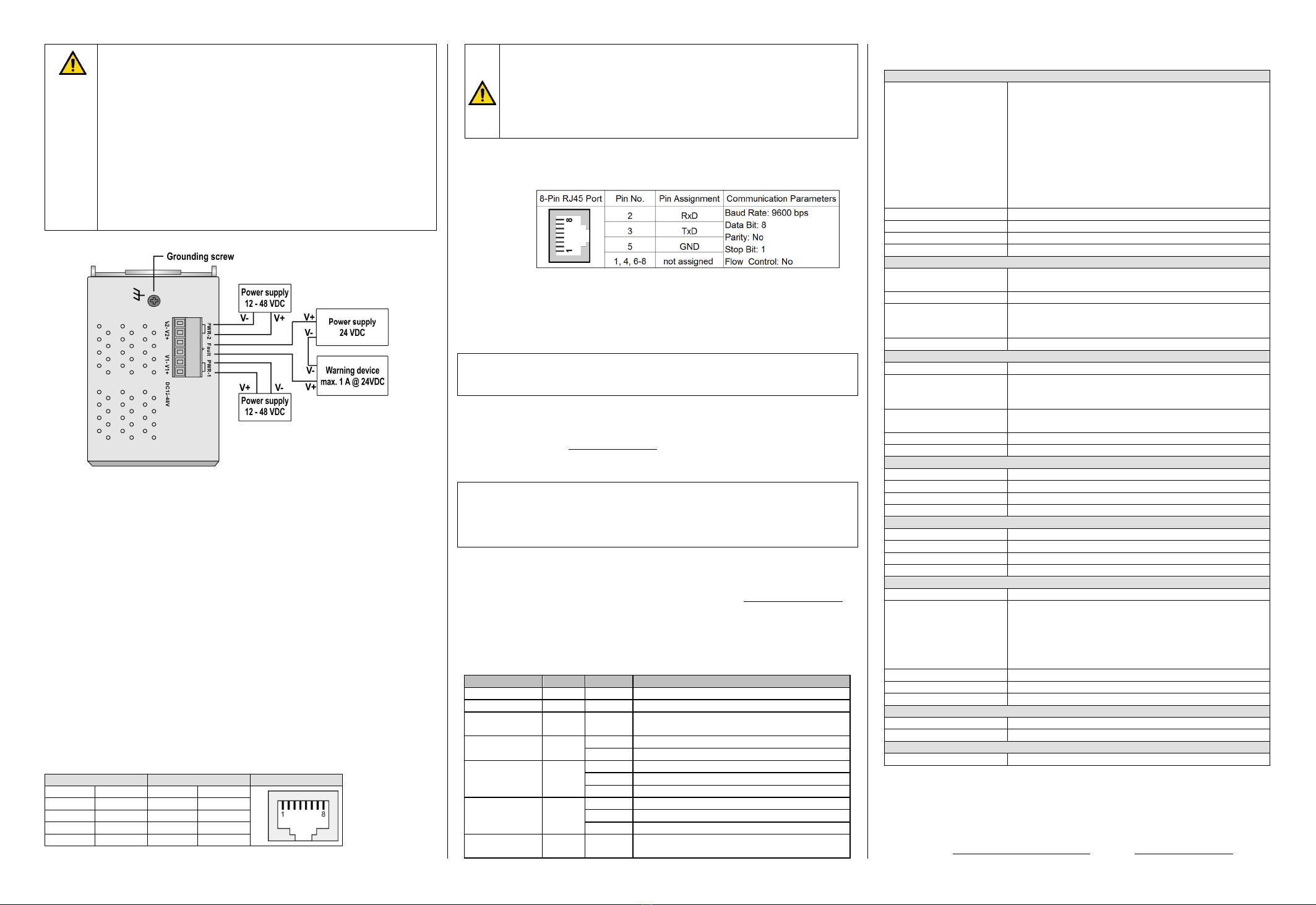
9.2 RS232 Console Port
The RS232 Interface with RJ45 connector can be used to access the switch console for
configuration.
Pinouts Serial
Console Port:
10. User Management
10.1 Device Access (Login to Web Interface)
The Web interface of the Switch can be accessed via following factory default settings:
IP address / Netmask: 192.168.1.110 / 255.255.255.0
User name: admin
Password: Detmold
Connect the PC to any Ethernet port of the managed Switch and set the PC’s IP
address to a free one of range 192.168.1.0 / 255.255.255.0
Start a web browser and enter the IP address of the connected Switch into the
browser’s address line (http://192.168.1.110). After the appearance of prompt (login)
enter the login credentials. After confirmation of your input with "OK" the home page of
the switch will be displayed.
Note: For more detailed information about configuration and use of the device features
please read the downloadable manual from Weidmüller’s website (Product catalogue 
Automation & Software Industrial Ethernet Advanced Line managed Switches 
Select Product Click and expand section „Downloads“ Download needed software
or documentation).
10.2 Reset Button
Press reset button for 2 to 3 seconds to reboot the switch (Warm Start).
Press reset button for >= 5 seconds to reset the switch to factory default settings.
11. LED Indicators
The front panel of the Ethernet Switch contains several LED indicators. The function of
each LED is described in the table below.
LED Color Status Description
PWR1 Green On Power is being supplied to power input PWR1.
PWR2 Green On Power is being supplied to power input PWR2.
R-MSTR
(Ring Master) Green On Is Ring Master of an enabled O-Ring.
Ring Green On O-Ring redundancy is enabled.
Blinking Ring structure is broken (No redundancy).
LNK/ACT Green
On Port’s link is active.
Off Port’s link is inactive.
Blinking Data is transmitted.
Full / Half
Duplex Amber
On Port is set to Full Duplex Mode.
Off Port is set to Half Duplex Mode.
Blinking Packet collisions detected.
FAULT Amber On Fault Relay indication for Power failure and
Port link loss.
12. Specifications
Technology
Ethernet Standards
IEEE 802.3 for 10BASE-T
IEEE 802.3u for 100BASE-TX
IEEE 802.3x for flow control
IEEE 802.3ad for port trunk with LACP
IEEE 802.1D for STP (Spanning Tree protocol)
IEEE 802.1w for RSTP (Rapid Spanning Tree protocol)
IEEE 802.1s for MSTP (Multiple Spanning Tree Protocol)
IEEE 802.1p for Class of Service
IEEE 802.1Q for VLAN Tagging
IEEE 802.1X for Authentication
IEEE 802.1AB for LLDP (Link Layer Discovery Protocol)
Processing Type Store and Forward
MAC Table size 8K
Packet buffer size 1 Mbit
Backplane bandwidth 3.2 Gbps
Interfaces
RJ45 Ports 10/100BASE-T(X) auto negotiation speed, F/H duplex
mode and auto MDI/MDI-X connection
RS232 Console Port RS232 Interface with RJ45 connector for Console access
LED Indicators
PWR1, PWR2 (Power), Fault (Relay), Ring Master, Ring
Status,
Port Link/Activity, Port Full/Half Duplex Mode
Relay Contact Max. 1A @ 24 V DC
Power
Input Voltage 24 V DC (12 - 48 V DC), 2 redundant inputs
Input Current 1.2 A @ 12 V DC
0.6 A @ 24 V DC
0.3 A @ 48 V DC
Connection One removable 6-pin terminal block, Wiring cable 12-
24AWG
Overload Current Protect. Present
Reverse Polarity Protect. Present
Physical Characteristics
Housing IP30 protection, metal
Dimension (W x H x D) 74.3 x 153.6 x 107.5 mm (2.93 x 6.05 x 4.2 inch)
Weight 931 g
Installation DIN-rail
Environmental conditions
Operating Temperature -40 to 75°C (-40 to 167°F)
Storage Temperature -40 to 85°C (-40 to 185°F)
Ambient Relative Humidity
5 to 95% (non-condensing)
Operating Altitude Up to 2000 m
Regulatory Approvals
Safety EN 62368-1; UL 61010-1; UL 61010-2-201
EMC
EN 55032, EN 55024, FCC Part 15 Subpart B Class A,
IEC 61000-4-2 ESD: Contact: 4 kV; Air: 8 kV,
IEC 61000-4-3 RS: 80 MHz to 1 Ghz: 3 V/m,
IEC 61000-4-4 EFT: Power: 0.5 kV; Signal: 0.5 kV,
IEC 61000-4-5 Surge: Power: 0.5 kV; Signal: 1 kV,
IEC 61000-4-6 CS: 3 Vrms
Shock IEC 60068-2-27
Free Fall IEC 60068-2-31
Vibration IEC 60068-2-6
MTBF
Time 886.987 hrs
Database Telcordia SR332
Warranty
Time Period 5 years
Contact Information
Weidmüller Interface GmbH & Co. KG
Klingenbergstraße 26, 32758 Detmold / Germany
Phone +49 (0) 5231 14-0, Fax +49 (0) 5231 14-292083
E-Mail weidmueller@weidmueller.com, Internet www.weidmueller.com

This manual suits for next models

1

Other Weidmüller Network Router manuals

Weidmüller IE-SW-AL10M-8TX-2GC Manual

Weidmüller

Weidmüller IE-SW-AL10M-8TX-2GC Manual

Weidmüller IE-SW-EL16-16TX Manual

Weidmüller

Weidmüller IE-SW-EL16-16TX Manual

Weidmüller IE-SW-AL08M-6TX-2GT Manual

Weidmüller

Weidmüller IE-SW-AL08M-6TX-2GT Manual

Weidmüller IE-SW-AL18M-16TX-2GC Manual

Weidmüller

Weidmüller IE-SW-AL18M-16TX-2GC Manual

Weidmüller IE-SR-2TX-WL Manual

Weidmüller

Weidmüller IE-SR-2TX-WL Manual

Weidmüller 2682250000 Manual

Weidmüller

Weidmüller 2682250000 Manual

Weidmüller IE-SW-AL14M-12GT-2GESFP Manual

Weidmüller

Weidmüller IE-SW-AL14M-12GT-2GESFP Manual

Popular Network Router manuals by other brands

movistar Zoovel Z-201 user manual

movistar

movistar Zoovel Z-201 user manual

Cisco 1841 - 1841 Integrated Services Router Hardware installation guide

Cisco

Cisco 1841 - 1841 Integrated Services Router Hardware installation guide

Belkin RT3200 user guide

Belkin

Belkin RT3200 user guide

Mercusys MR60X user guide

Mercusys

Mercusys MR60X user guide

Conel ER75i v2 SL Start guide

Conel

Conel ER75i v2 SL Start guide

Abocom MH200 Quick installation guide

Abocom

Abocom MH200 Quick installation guide

Nortel business policy switch 2000 user manual

Nortel

Nortel business policy switch 2000 user manual

SignaMax 065-7418POETB user guide

SignaMax

SignaMax 065-7418POETB user guide

Samsung SmartThings Wifi ET-WV525 user manual

Samsung

Samsung SmartThings Wifi ET-WV525 user manual

Encore Networks VSR-30 installation guide

Encore Networks

Encore Networks VSR-30 installation guide

Allied Telesis AT-GS950/8 installation guide

Allied Telesis

Allied Telesis AT-GS950/8 installation guide

Westermo RFI-219-T3G user guide

Westermo

Westermo RFI-219-T3G user guide

D-Link DSL-2680 Quick installation guide

D-Link

D-Link DSL-2680 Quick installation guide

Sercomm Wingle quick start guide

Sercomm

Sercomm Wingle quick start guide

Craftsman 315.17480 owner's manual

Craftsman

Craftsman 315.17480 owner's manual

HP A58x0AF Bck(pwr)-Frt(ports) Product End-of-Life Disassembly Instructions

HP

HP A58x0AF Bck(pwr)-Frt(ports) Product End-of-Life Disassembly Instructions

Drill Master 61626 Owner's manual & safety instructions

Drill Master

Drill Master 61626 Owner's manual & safety instructions

Bosch PR10E Operating/safety instructions

Bosch

Bosch PR10E Operating/safety instructions

manuals.online logo
manuals.online logoBrands
  • About & Mission
  • Contact us
  • Privacy Policy
  • Terms and Conditions

Copyright 2025 Manuals.Online. All Rights Reserved.