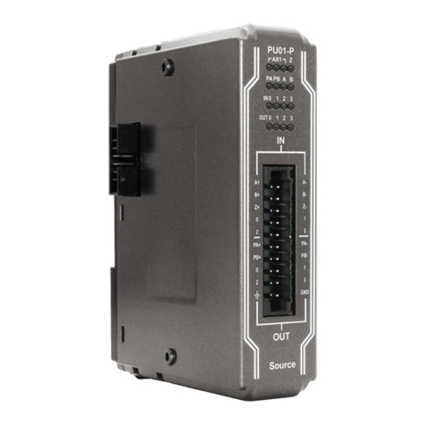
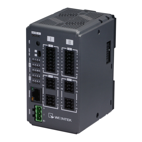
weintek iR-ETN40P User manual

User Manual
iR-ETN40R/P User Manual
This guide walks through important information about iR-ETN40R/P
UM021002E_20231220

Table of Contents
1. Product Overview ...................................................................................................1
1.1 iR-ETN40R ......................................................................................................1
1.2 iR-ETN40P.......................................................................................................1
2. Specifications..........................................................................................................2
3. LED Indicators .........................................................................................................4
3.1 IO RUN/ERR LED.............................................................................................4
3.2 ENET RUN/ERR ...............................................................................................4
3.3 RJ45 ................................................................................................................4
4. Reset Button ...........................................................................................................5
5. I/O Display Switch...................................................................................................5
6. IP Address Setup .....................................................................................................5
7. MODBUS Mapping..................................................................................................6
7.1 Bit Mapping....................................................................................................6
7.2 Register Mapping ...........................................................................................6
7.3 TCP/IP Register ...............................................................................................6
7.4 Device Information Register...........................................................................7
7.5 iBus Information Register...............................................................................7
7.6 Module Information Register.........................................................................7
7.7 Module Register.............................................................................................8
7.8 Product Code List ...........................................................................................8
7.9 Special Register ..............................................................................................8
7.10 Life Guarding Register ....................................................................................9
7.11 The Default Value...........................................................................................9
7.12 Device Error Code List ..................................................................................10
7.13 Reading and Writing iR-PU01-P Objects ......................................................10
7.14 iR-PU01-P NMT Control Address..................................................................11
7.15 Run/Stop Register ........................................................................................11
7.16 Pulse Capture Feature..................................................................................12
7.17 High-speed Input Function ..........................................................................12
7.17.1 Function block..............................................................................12
7.17.2 Register List ..................................................................................13
7.17.3 Input configuration ......................................................................16
7.17.4 Rate Measurement ......................................................................18
7.17.5 Simple Counter.............................................................................19
7.17.6 High Speed Counter .....................................................................23
7.17.7 Application Examples...................................................................30
7.17.7.1 Flow Control.................................................................30

7.17.7.2 Speed Control...............................................................31
7.17.7.3 Length Measurement...................................................32
8. Modbus Mapping .................................................................................................35
8.1 iBus Information Register.............................................................................35
8.2 Digital Input Bit Mapping to Modbus ..........................................................35
8.3 Digital Output Bit Mapping to Modbus .......................................................36
8.4 Analog Input Mapping to Modbus...............................................................36
8.5 Analog Output Mapping to Modbus............................................................36
8.6 Module Register Mapping to Modbus.........................................................36
8.7 iR-PU01-P Variable Instance Mapping .........................................................37
9. EtherNet/IP Object ...............................................................................................39
9.1 Object List ....................................................................................................39
9.2 Identity Objects............................................................................................39
9.2.1 Service..........................................................................................39
9.2.2 Class Attributes ............................................................................39
9.2.3 Instance Attributes.......................................................................39
9.3 Message Router Object................................................................................40
9.3.1 Class Attributes & Instance Attributes .........................................40
9.4 Assembly Object ..........................................................................................40
9.4.1 InstanceAttributes........................................................................40
9.5 Connection Manager Object........................................................................40
9.5.1 Class Attributes & Instance Attributes .........................................40
9.6 Ethernet Link Object ....................................................................................40
9.6.1 Services ........................................................................................40
9.6.2 Class Attributes ............................................................................40
9.6.3 Instance Attributes.......................................................................40
9.7 TCP/IP Interface Object ................................................................................41
9.7.1 Service..........................................................................................41
9.7.2 Class Attributes ............................................................................41
9.7.3 Instance Attributes.......................................................................41
9.7.4 Interface Status ............................................................................42
9.7.5 Configuration Control Attribute...................................................42
9.8 Module Register object................................................................................42
9.8.1 Service..........................................................................................42
9.8.2 Class Attribute..............................................................................42
9.8.3 Instance Attributes.......................................................................42
9.9 iBus Object ...................................................................................................43
9.9.1 Services ........................................................................................43

9.9.2 Class Attribute..............................................................................43
9.9.3 Instance Attributes.......................................................................43
9.10 Axis Register Object .....................................................................................44
9.10.1 Services ........................................................................................44
9.10.2 Class Attributes ............................................................................44
9.10.3 Instance Attributes.......................................................................44
9.11 High Speed Counter Object..........................................................................45
9.11.1 Services ........................................................................................45
9.11.2 Instance Attributes.......................................................................45
10. iBus Error Handling ...............................................................................................46
11. Power Consumption .............................................................................................48
12. EasyRemoteIO.......................................................................................................49
13. Description File .....................................................................................................52
13.1 Weintek HMI Tag..........................................................................................52
13.2 EtherNet/IP EDS ...........................................................................................52
13.3 CODESYS PLCopen.XML................................................................................52
14. IO Wiring...............................................................................................................55
14.1 iR-ETN40R ....................................................................................................55
14.2 iR-ETN40P.....................................................................................................56
15. Firmware Update..................................................................................................56
15.1 Software.......................................................................................................56
15.2 Firmware Update .........................................................................................58
15.3 Notes on Updating Firmware.......................................................................58

iR-ETN40R/P User Manual
1
1. Product Overview
1.1 iR-ETN40R
a.d
Input Terminal
b.c.e.f
Output Terminal
g
Reset Button
h
I/O Display Switch
i
Ethernet Port
j
Power Connector
k
Expansion Connector
1.2 iR-ETN40P
a.b
Input Terminal
c.d
Output Terminal
e
Reset Button
f
I/O Display Switch
g
Ethernet Port
h
Power Connector
i
Expansion Connector

iR-ETN40R/P User Manual
2
2. Specifications
Communication Interface Specifications
No. of Ports
1
Data Transfer Rate
10/100 Mbps
Data Transfer Medium
4 x 2 twisted pair copper cable; category 3 (10 Mbps), category 5 (100
Mbps)
Distance Between Stations
100 m between hub/switch and Bus Coupler or between Bus Coupler
and Bus Coupler
Protocol
Modbus TCP Server, EtherNet/IP adapter
Max. Number of TCP/IP Connections
8 connections
Network to Logic Isolation
Yes
Digital Output
Module Name
iR-ETN40R
iR-ETN40P
Total Number of Outputs
16
16
Output Type
Relay
Source
Output Voltage
250VAC/30VDC
11~28VDC
Output Current
2A per channel (Max 8A)
0.5A per channel (Max 4A)
Response Time
10 ms
OFF->ON: 100 μs
ON->OFF: 600 μs
Isolation
Yes, electromagnetic isolation
Yes, optocoupler isolation
High-speed Output
Module Name
iR-ETN40R
iR-ETN40P
Total Number of Outputs
0
2
Output Type
N/A
Source
Output Voltage
N/A
5VDC
Output Current
N/A
50mA per channel
Max. Output Frequency
N/A
40KHz
Isolation
N/A
Yes, optocoupler isolation
Digital Input
Total Number of Inputs
24
Isolation
Yes, optical isolation
General Input
Total Number of Inputs
20
Input Type
Sink or Source
Logic 1 Input Voltage
15~28 VDC
Logic 0 Input Voltage
0~5 VDC
Response Time
OFF->ON: 5 ms
ON->OFF: 1 ms
High-speed Input
Total Number of Inputs
4
Input Type
SINK INPUT (PNP)*
Logic 1 Input Voltage
15~28 VDC
Logic 0 Input Voltage
0~5 VDC
Max. Input Frequency
20KHz
Expansion I/O Module
Number of Bus Terminals
Depends on Power Consumption (Please see section 5 in this datasheet)
The maximum allowable number of iR modules is 16 modules.
Digital Input Point
Max. 224 (Including 24 built-in points and the max. allowable number is
248 points.)
Digital Output Point
Max. 112 (Including 16 built-in points and the max. allowable number is
128 points.)
Analog Input Channel
Max. 64
Analog Output Channel
Max. 64

iR-ETN40R/P User Manual
3
Indicators
ENET
Green
Device Status Indicator
Red
Device Error Indicator
IO
Green
Module Status Indicator
Red
Module Error Indicator
General Specification
Power
Module Name
iR-ETN40R
iR-ETN40P
Power Supply
24 VDC (-15%/+20%)
Power Dissipation
Nominal 255mA@24VDC,
Max. 540mA@24VDC
Nominal 100mA@24VDC,
Max. 530mA@24VDC
Current for Internal Bus
Max. 2A@5VDC
Current Consumption
520mA@5VDC
350mA@5VDC
Electrical Isolation
Logic to Field Power Isolation: Yes
Back-up Fuse
≤ 1.6A Self-recovery
Specification
PCB Coating
Yes
Enclosure
Plastic
Dimensions WxHxD
64 x 109 x 81 mm
Weight
Approx. 0.27 kg
Mount
35mm DIN rail mounting
Environment
Protection Structure
IP20
Storage Temperature
-20°~ 70°C (-4°~ 158°F)
Operating Temperature
-10°~ 60°C (14°~ 140°F)
Relative Humidity
10% ~ 90% (non-condensing)
Certification
CE
CE marked
* Refer to wiring diagram - High Speed Input

iR-ETN40R/P User Manual
4
3. LED Indicators
3.1 IO RUN/ERR LED
Display Module Status
RUN LED
ERR LED
Description
OFF
OFF
Power off or no expansion module is connected
Blinking
OFF
IO initiating
Blinking
ON
IO initiation error
ON
OFF
IO working
ON
Blinking
IO module alarm
ON
ON
IO communication fault
Blinking
Blinking
Exceeding power limit or too many modules
3.2 ENET RUN/ERR
Run LED
Err LED
Description
Modbus TCP
EtherNet/IP
OFF
OFF
Power off or no power
Blinking
OFF
Communicating
Pre-operational mode
ON
OFF
The device is in the OPERATIONAL state
OFF
ON
Hardware error,
communication fault
24V power error or
hardware error,
communication fault
ON
Blinking
Reset button is triggered
Reset button is triggered or
a recoverable error has
occurred
ENET Run/ERR indicator can be set to Modbus TCP mode (default) or EtherNet/IP
mode. The communication address for Modbus TCP mode is 1013 (0x03F5 in Hex).
Communication mode setting: In “Config Data”set 0 to use Modbus TCP mode or set
1 to use EtherNet/IP mode.
3.3 RJ45
LINK /ACT LED
OFF
No communication
Green
Blinking
There is activity on this port
Speed LED
OFF
Connection speed: 10Mbps
Orange ON
Connection speed: 100Mbps

iR-ETN40R/P User Manual
5
4. Reset Button
Press and hold the reset button for 2 seconds until ENET ERR LED blinks to reset
network settings to default (see table below).
Press and hold the reset button for 5 seconds until ENET ERR LED turns ON to restore
factory default.
Item
Description
Default
1
IP Address
192.168.0.212
2
Netmask
255.255.255.0
5. I/O Display Switch
The I/O on iR-ETN40R/P are split into two Terminals: TerminalⅠand TerminalⅡ.
When the I/O Display Switch is flipped upward, the indicators show the states of I/O
in TerminalⅠ, and when the switch is flipped downward, the indicators show the
states of I/O in TerminalⅡ.
6. IP Address Setup
Network parameters can be configured using EasyRemote IO, and factory defaults
can be restored by pressing the Reset Button. Please find the chapter about
EasyRemote IO in this user manual for more information.
Item
Description
Default
1
IP Address
192.168.0.212
2
Netmask
255.255.255.0

iR-ETN40R/P User Manual
6
7. MODBUS Mapping
7.1 Bit Mapping
Parameter
Start address
Read/Write
Function Code
Dec
Hex
Digital Input
0~511
0000~
01FF
Read
2
Digital Output
0~511
0000~
01FF
Read
1
Write
5,15
7.2 Register Mapping
Parameter
Start address
Read/Write
Function Code
Dec
Hex
Analog Input
0~255
0000~
00FF
Read
3,4,23
Analog Output
256~511
0100~
01FF
Read
3,23
Write
6,16,23
Digital Input
800~863
0320~
035F
Read
3,23
Digital Output
864~927
0360~
039F
Read
3,23
Write
6,16,23
Registers
----------
Read
3,4,23
---------
Write
6,16,23
*The value in 32-bit register is placed in Little Endian Byte Order: the least significant
byte of the data is placed at the byte with the lowest address.
Example: When the value is 100000 (0x0001 86A0), then the data is placed in the
following way.
7.3 TCP/IP Register
Address
Read/Write
Data Size
Description
Dec
Hex
1000
03E8
Read
3word
(MAC-address) Ethernet physical address
If 00-0C-26-01-02-03, then 0x000C, 0x2601, 0x0203.
1003
03EB
Read/Write
2word
IP address
If 192.168.0.212, then 0xC0A8, 0x00D4.
1005
03ED
Read/Write
2word
subnet mask
If 255.255.255.0, then 0xFFFF, 0xFF00
1011
03F3
Read
1word
Number of TCP/IP connections
*TCP/IP Register Settings will take effect after cold reset or after given Device Reset
Warm command.
86 A0
00 01
03
04
Function Code
Data Length
Low Byte
High Byte

iR-ETN40R/P User Manual
7
7.4 Device Information Register
Address
Read/Write
Data size
Description
Dec
Hex
3000
0BB8
Read
4word
Vendor name string 8 char: “weintek” (ASCII)
3004
0BBC
Read
1word
Product Code of iR-ETN40R: 0x0A73, iR-ETN40P: 0x0A71
3005
0BBD
Read
1word
Firmware revision V1.23.4, 0x1234
3006
0BBE
Read
1word
Hardware revision V1.23.4, 0x1234
3007
0BBF
Read
1word
Power consumption unit mW
3008-
3023
0BC0-
0BCF
Read/Write
16word
Product name, default: “iR-ETN40R”(ASCII)
7.5 iBus Information Register
Address
Read/Write
Data size
Description
Dec
Hex
10000
2710
Read
1word
Slot 0 iR-ETN40R/P Product code
10001
2711
Read
1word
Slot 1 Module Product code
10001~
10016
2712~
2720
Read
1word
Slot 2~Slot 16 Module Product code
10033
2731
Read
1word
Number of modules
10035
2733
Read
1word
Number of points of Digital Input
10036
2734
Read
1word
Number of points of Digital Output
10037
2735
Read
1word
Number of Analog channels of Input register
10038
2736
Read
1word
Number of Analog channels of Output register
10045
273D
Read/Write
1word
0: iBus stops when one of the modules is disconnected.
1: iBus continues running when one of the modules is
disconnected.
7.6 Module Information Register
The data size of the information register of each module is 100word. If the first
module starts from address 30000 to 30099, then the second module starts from
address 30100 to 30199, and so on.
Address
Read/Write
Data size
Description
Dec
Hex
30000
~30099
7530~
7594
Read
100word
Module information of Slot 1
30100
~31599
7535~
7B6F
Read
100word
Module information of Slot 2~16
Ex: Module information of slot 1
Address
Read/Write
Data size
Description
Dec
Hex
30000
7530
Read
1word
Module product code
30001
7531
Read
1word
Module firmware version V1.23.4, value 0x1234
30002
7532
Read
1word
Module hardware version V1.23.4, value 0x1234
30003
7533
Read
1word
Power consumption unit mW
30038
7556
Read
1word
Number of points of Digital Output

iR-ETN40R/P User Manual
8
30039
7557
Read
1word
Number of points of Digital Input
30040
7558
Read
1word
Number of Analog input channels of module
30041
7559
Read
1word
Number of Analog output channels of module
7.7 Module Register
Each module is configured with different parameters; please see the corresponding
manual of the module used. The maximum total data size of the registers is 500word.
If the first module starts from address 20000 to 20499, then the second module
starts from address 20500 to 20999, and so on.
Address
Read/Write
Data size
Description
Dec
Hex
20000
~20499
4E20~
5013
Read
500word
Module information of Slot 1
20500
~27999
5014~
6D5F
Read
500word
Module information of Slot 2~16
7.8 Product Code List
Item
Product
Code
1
iR-DI16-K
0154h
2
iR-DM16-P
0351h
3
iR-DQ16-P
0251h
4
iR-DM16-N
0352h
5
iR-DQ16-N
0252h
6
iR-DQ08-R
0243h
7
iR-AQ04-VI
0525h
8
iR-AI04-VI
0425h
9
iR-AM06-VI
0635h
10
iR-AI04-TR
0426h
11
iR-ETN
0702h
12
iR-ETN40R
0A73h
13
iR-ETN40P
0A71h
7.9 Special Register
Address
Read/Write
Data size
Description
Dec
Hex
1013
03F5
Read/Write
1word
Indicator Mode:
0: Modbus TCP
1: EtherNet IP
1014
03F6
Read/Write
1word
Disable Reset Button
5AA5h:Reset Button is ineffective.
1015
03F7
Read/Write
1word
Register Save Setting
0: Parameters are saved when the value is changed
in the register.
1: Parameters are not saved when the value is
changed in the register.
The value in the register is 0 after each boot.
5000
1388
Read
1word
Device Error Code

iR-ETN40R/P User Manual
9
5001
1389
Read
1word
Reserved
5002
138A
Read
1word
Slot1~16 of Module disconnected
6000
1770
Write
1word
Device Command
0x5269:Reset iBus
0x5250:Set parameter to default without TCP/IP
0x5257:Device Reset Warm
7.10 Life Guarding Register
If the communication was missing for longer than the Life Guarding Time, a Life
Guard Event is indicated. The output behavior is determined by whether Error Mode
is enabled or disabled. Enabling Error Mode will output an Error Value when an event
occurs. Disabling Error Mode will keep the last value (for both digital and analog).
Address
Read/Write
Data size
Description
Dec
Hex
6100
17D4
Read/Write
1word
Life Guarding Time, unit: ms, 0: Disabled
6101
17D5
Read/Write
1word
Digital Output Error Mode (bit15-0)
0:Keep last value
1:Error value
6102
17D6
Read/Write
1word
Digital Output Error Mode (bit31-16)
…..
…..
…..
…..
…..
6132
17F4
Read/Write
1word
Digital Output Error Mode (bit511-495)
6133
17F5
Read/Write
1word
Digital Output Error Value (bit15-0)
0: Off
1: On
6134
17F6
Read/Write
1word
Digital Output Error Value (bit31-16)
…..
…..
…..
…..
…..
6164
1814
Read/Write
1word
Digital Output Error Value (bit511-495)
6165
1815
Read/Write
1word
Analog Output Error Mode
(channel 15-0)
0:Keep last value
1:Error value
6166
1816
Read/Write
1word
Analog Output Error Mode
(channel 31-16)
6167
1817
Read/Write
1word
Analog Output Error Mode
(channel 47-32)
6168
1818
Read/Write
1word
Analog Output Error Mode
(channel 63-48)
6169~
6232
1819~
1858
Read/Write
64word
Analog Output Error Value
(channel 63-0)
-32768~32768
7.11 The Default Value
Address
Read/Write
Data size
Description
Default
Dec
Hex
3008-
3023
0BC0-
0BCF
Read/Write
16word
Product name
“iR-ETN40R”
6100
17D4
Read/Write
1word
Life Guarding Time
0
6101-
6132
17D4-
17F4
Read/Write
32 word
Digital Output Error Mode
0xFF
6133-
6164
17F5-
1814
Read/Write
32 word
Digital Output Error Value
0
6165-
6168
1815-
1818
Read/Write
4word
Analog Output Error Mode
0xFF
6169-
6232
1819~
1858
Read/Write
64word
Analog Output Error Value
0

iR-ETN40R/P User Manual
10
*After pressing [Reset] button, the Default Value will be filled into the corresponding
registers.
7.12 Device Error Code List
Refer to special register address 5000/1388H
Bit Number
Description
Bit0
Low power alarm
Bit1
iBus initialization fault
Bit2
Hardware error
Bit3
Module lost connection
Bit4
Module alarm
Bit5
Number of iBus exceeds 16
Bit6
Power consumption exceeded at iBus system
Bit7
Max. number of TCP connections exceeded
Bit8
iBus is off
Bit9
A life guarding or EIP timeout event has occurred
Bit10
Modbus connection timed out
Bit11
EtherNet/IP Timeout
Bit12
Reserved
Bit13
Reserved
Bit14
Built-in I/O module error
Bit15
Reserved
7.13 Reading and Writing iR-PU01-P Objects
Please see iR-PU01-P user manual for more information about index, sub-index, and
length.
R/W
Address
(Hex)
Description
Write
Object
0xFFF0
Index
0xFFF1
Sub-index (High Byte)
Length (Low Byte)
0xFFF2
Hi Byte
0x56
WORD
DWORD
Lo Byte
0x78
BYTE
0xFFF3
Hi Byte
0x12
Lo Byte
0x34
Sequentially writes data into 0xFFF0~0xFFF3. Data will be sent to iR-PU01-P when written

iR-ETN40R/P User Manual
11
into 0xFFF3.
Read
Object
0xFFF4
Index
0xFFF5
Sub-index (High Byte)
Length (Low Byte)
0xFFF6
Hi Byte
0x56
WORD
DWORD
Lo Byte
0x78
BYTE
0xFFF7
Hi Byte
0x12
Lo Byte
0x34
Step1: Sequentially writes data into 0xFFF4~0xFFF5. Reading iR-PU01-P object starts when
data is written into 0xFFF5, and the data will be placed in 0xFFF6~0xFFF7.
Step 2: Read data of 0xFFF6~0xFFF7 Object.
7.14 iR-PU01-P NMT Control Address
NMT Address
State
Value
0xFFF8(65528)
Stop
0x0001
Operation
0x0002
Pre-operational
0x0080
Reset application
0x0081
Reset communication
0x0082
7.15 Run/Stop Register
The RunStop Pin function allows designation of an input as RunStop Input Point. In
Run mode, the device can output value normally, and in Stop mode, the output value
will be ineffective. When the mode is switched from Run to Stop, please find the
description of error (Modbus address 6101~6232).
Address
Read/Write
Name
Value
Dec
Hex
1200
04B0
Read/Write
RunStop Mode
0
Not in use (Default)
1
Input: ON
Run
Input: OFF
Stop
2
Input: ON
Stop
Input: OFF
Run
1201
04B1
Read/Write
RunStop Input Point
Value 0~255 = Input Point 0~255
The default is 0.
1202
04B2
Read
RunStop State
0
STOP
1
Run
-1
Not in use
-2
Error in the setting of RunStop
Mode
-3
Error in the setting of RunStop

iR-ETN40R/P User Manual
12
input
7.16 Pulse Capture Feature
iR-ETN40R/P provides a pulse capture feature which can be used for the local digital
inputs. This feature can be used to capture high-going pulses or low-going pulses that
are of such a short duration that they would not always be seen when the controller
reads the digital inputs at the beginning of the scan cycle. When pulse capture
feature is enabled for an input, a change in state of the input is latched and held until
the next input cycle update. This ensures that a pulse which lasts for a short period
of time is caught and held until the controller reads the inputs.
Illustration of Pulse Capture
Address
Read/Write
Name
Value
Dec
Hex
6300
189C
Read/Write
Pulse capture feature for local
digital inputs 0~11 in TerminalⅠ.
Bit0~Bit11 correspond to inputs
0~11. Bit12~15 are reserved.
Bit value:
0:Disable
1:Enable
6301
189D
Read/Write
Pulse capture feature for local
digital inputs 16~23 in TerminalⅡ.
*This feature is only supported for the local digital inputs of IR-ETN40R/P
7.17 High-speed Input Function
7.17.1 Function block
iR-ETN40R/P offers 4 high-speed inputs (Input Points 10, 11 of TerminalⅠand Input
Points 10, 11 of Terminal Ⅱ). These high-speed inputs can be flexibly configured, as
the application may require, for high-speed counter use, for A/B phase encoder use,
or for measurement of high-speed pulse.
CPU Input Update
CPU Input Update
Scan Cycle
Next Scan Cycle
External Input
Pulse Capture Disabled
Pulse Capture Enabled
CPU misses the pulse
CPU catches the pulse

iR-ETN40R/P User Manual
13
7.17.2 Register List
The maximum input frequency for a counter is 20 KHz. When the input points are
configured for A/B phase (Quadrature 4X) encoder use, the maximum input
frequency is 10 KHz.
Name
Address(Dec)
Input Function
TerminalⅠHigh-speed Input
Function
4044
TerminalⅡHigh-speed Input
Function
4045
Rate Measurement
Time-Windows
4028
Windows Channel
4029
Rate Value
4030-4031
Simple
Counter
Simple
Counter-0
Counter Value
4000~4001
Counter State
4008
Counter Command
4012
Upper Limit Value
4020~4021
Digital
Output
Point
4080
ON-trigger Value
4084~4085
OFF -trigger Value
4092~4093
Simple
Counter-1
Counter Value
4002~4003
Counter State
4009
Counter Command
4013
Upper Limit Value
4022~4023
Digital
Point
4081
High
Speed
Input
Simple
Counter 0-3
Bidirectional
Counter 0-1
Rate
Measurement
Digital Output
Digital Output
Select
Counter
Start/Stop
&Reset
Limit
Limit

iR-ETN40R/P User Manual
14
Output
ON-trigger Value
4086~4087
OFF -trigger Value
4094~4095
Simple
Counter-2
Counter Value
4004~4005
Counter State
4010
Counter Command
4014
Upper Limit Value
4024~4025
Digital
Output
Point
4082
ON-trigger Value
4088~4089
OFF -trigger Value
4096~4097
Simple
Counter-3
Counter Value
4006~4007
Counter State
4011
Counter Command
4015
Upper Limit Value
4026~4027
Digital
Output
Point
4083
ON-trigger Value
4090~4091
OFF-trigger Value
4098~4099
Bidirectional
Counter
Counter-0
Counter Value
4046~4047
Upper Limit
4050~4051
Upper Limit Reload Value
4058~4059
Lower Limit
4054~4055
Lower Limit Reload Value
4062~4063
Digital
Output
0
Point
4200
ON-trigger Value
4201~4202
OFF-trigger Value
4203~4204
1
Point
4205
ON-trigger Value
4206~4207
OFF-trigger Value
4208~4209
2
Point
4210
ON-trigger Value
4211~4212
OFF-trigger Value
4213~4214
3
Point
4215
ON-trigger Value
4216~4217
OFF-trigger Value
4218~4219
4
Point
4220
ON-trigger Value
4221~4222
OFF-trigger Value
4223~4224
5
Point
4225
ON-trigger Value
4226~4227
OFF-trigger Value
4228~4229
6
Point
4230
ON-trigger Value
4231~4232
OFF-trigger Value
4233~4234
7
Point
4235
ON-trigger Value
4236~4237
OFF-trigger Value
4238~4239
Counter-1
Counter Value
4048~4049
Upper Limit
4052~4053

iR-ETN40R/P User Manual
15
Upper Limit Reload Value
4060~4061
Lower Limit
4056~4057
Lower Limit Reload Value
4064~4065
Digital
Output
0
Point
4240
ON-trigger Value
4241~4242
OFF-trigger Value
4243~4244
1
Point
4245
ON-trigger Value
4246~4247
OFF-trigger Value
4248~4249
2
Point
4250
ON-trigger Value
4251~4252
OFF-trigger Value
4253~4254
3
Point
4255
ON-trigger Value
4256~4257
OFF-trigger Value
4258~4259
4
Point
4260
ON-trigger Value
4261~4262
OFF-trigger Value
4263~4264
5
Point
4265
ON-trigger Value
4266~4267
OFF-trigger Value
4268~4269
6
Point
4270
ON-trigger Value
4271~4272
OFF-trigger Value
4273~4274
7
Point
4275
ON-trigger Value
4276~4277
OFF-trigger Value
4278~4279

iR-ETN40R/P User Manual
16
7.17.3 Input configuration
Point10
Point11
TerminalⅠ
SC-0
Point10
Point11
TerminalⅡ
Simple Counter-0
Simple Counter-1
Bidirectional
Counter -0
SC-0
Simple Counter-2
Simple Counter-3
Bidirectional
Counter -1
Reset
Start/Stop
Reset
Start/Stop
Other manuals for iR-ETN40P
1
This manual suits for next models
1
Table of contents
Other weintek Control Unit manuals
Popular Control Unit manuals by other brands

Agilent Technologies
Agilent Technologies 54751A manual

Metabolic Devices
Metabolic Devices Coherence How to begin

Chamberlain
Chamberlain 41D7742-7 manual

Motorline professional
Motorline professional MC61PL installer and user manual

Bradley
Bradley EFX 120 Series Installation

Masibus
Masibus MAS-AI-08-D manual

LDM
LDM RV 102 Instruction for installation and maintenance

Sena
Sena Parani ESD100V2 quick start guide

TechnipFMC
TechnipFMC Smith Meter 210 Installation, operation & service manual

OSF
OSF Poolcontrol-30-Vario Installation and operating instructions

IFM
IFM AS interface E70188 installation instructions

exemys
exemys RME2-AI user manual