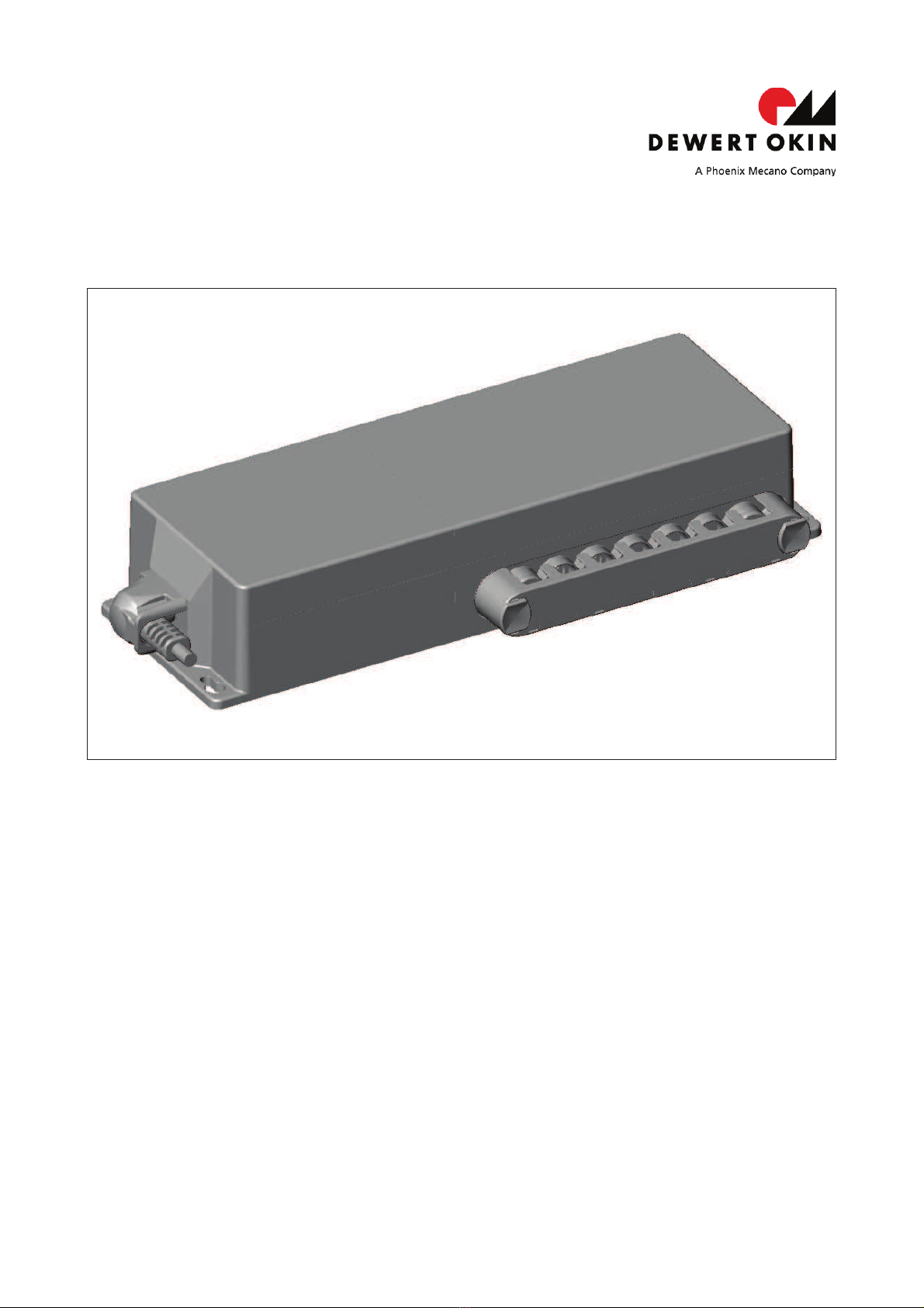
Phoenix Mecano Dewert Okin SG 300 User manual

SG(AG) 300 control unit
Installation Instructions
(Translation of the original installation instructions)


SG(AG) 300 control unit Foreword
75082(-) 3
Foreword
Disclaimer and Exclusion of Liability
DewertOkin is not responsible for damage resulting from:
Failure to observe these instructions,
Changes made to this product which have not been approved by DewertOkin, or
The use of replacement parts which have not been approved or manufactured by DewertOkin.
Contact address
DewertOkin GmbH
Weststraße 1
32278 Kirchlengern
Germany
Tel: +49 (0
)5223/979-0
Creation of a complete operating instruction manual for the entire end product
These instructions are only intended to be used by the end-product manufacturer. They should not
be given to the operator of the end product. The factual information contained within may be used
as a basis when creating the end-product manual.
The warning and danger notices are best suited for use in the end product's manual. However it is
not sufficient to simply follow these notices. You should also carry out an internal risk assessment
for your end product. This can then be used as the basis for the safety notices in your manual.
Usage in medical products
The SG(AG) 300 control unit is not a medical product. If used in a medical end product, you (the
end manufacturer) are obliged to ensure compliance with EC directives and to ensure that other
pertinent medical product regulations are maintained.

Table of contents SG(AG) 300 control unit
4 75082(-)
Table of contents
Foreword 3
Disclaimer and Exclusion of Liability 3
Contact address 3
Creation of a complete operating instruction manual for the entire end product 3
Usage in medical products 3
Table of contents 4
1. General Information 5
1.1 About these installation instructions 5
1.2 Conventions used 5
2. Safety Notices 6
2.1 Proper and Intended Usage 6
2.2 Selection and qualification of personnel 7
2.3 Notice on safety during operations 7
2.4 Product labelling 8
3. Possible combinations 9
3.1 Control unit variants 9
3.2 Layout of system connections 9
4. Device description 10
4.1 Components 10
5. Technical data 14
6. Installation 16
6.1 Safety notices to observe during installation 16
6.2 Installation procedure 17
7. Operating Notes 24
7.1 General information 24
7.2 Notice for operating with optional configuration 26
8. Troubleshooting 27
9. Maintenance 29
9.1 Maintenance 29
9.2 Cleaning and care 30
10. Disposal 31
EU Declaration of Conformity 32

SG(AG) 300 control unit General Information
75082(-) 5
1. General Information
1.1 About these installation instructions
In order to install the SG(AG) 300 control unit successfully and safely in the end product, these instal-
lation instructions must be observed. These instructions are not an operating manual for the end
product.
These instructions will help you to minimize danger, repair costs and down times. They will also
help you to maximize the reliability and lifespan of the end product.
CAUTION
The notices in these instructions must be followed!
Following the guidelines during i
n-
stallation and connection procedures will help t
o minimize:
the risk of accident and injury, and
damage to the SG(AG) 300 control unit or the end product.
These installation instructions have been written with due care and attention. However, we cannot
guarantee that the data, images and drawings are complete and correct nor do we accept any li-
ability for the information contained therein, unless required by law.
uWe reserve the right to make unannounced technical changes in the course of our continual
product improvement process!
1.2 Conventions used
Notices which do not relate to safety are indicated in these instructions with a symbol:
uTriangular notice symbol
Explanations of warning notices
DANGER
DANGER indicates a hazardous situation which, if not avoided, will result in serious in-
jury or death.
WARNING
WARNING indicates a hazardous situation which, if not avoided, could result in ser
i
ous
injury or death.
CAUTION
CAUTION indicates a hazardous situation which, if not avoided, could result in m
i
nor or
moderate i
njury.
NOTICE
N
OTICE about a harmful situation, possible consequences: the product itself or sur-
rounding objects could be da
maged.

Safety Notices SG(AG) 300 control unit
6 75082(-)
2. Safety Notices
2.1 Proper and intended usage
The SG(AG) 300 control unit is designed for use
as a control unit and power supply for the appropriate DewertOkin drive systems.
it can be used for care purposes (CARE model).
it can be used in a hospital (HOSP model).
CAUTION
The SG(AG) 300 control unit should only be used for the applications described
above.
Any other form of usage is not permitted and can lead to accidents or destru
c-
tion of the unit. Such non
-approved applications will lead immediately to the expira
tion
of all guarantee and warranty claims on the part of the end
-product manufacturer
against the manufa
cturer.
2.1.1 Improper usage
Be sure to follow the notices below concerning improper usage. You should include them in
your product manual in order to inform the users of your end product.
WARNING
The SG(AG) 300 control unit should not be used:
in any environment where combustible or explosive gases or vapours (e.g., anae
s-
thesiology) may be present,
in the proximity of open fires or other heat sources (such as furnaces, ovens or d
i-
rect sunlight),
as a power source for toys or games,
in any application that will be cleaned with an automated washing system,
outdoors.
CAUTION
The SG(AG) 300 control unit may not be operated by:
by small children,
by frail or infirm persons without supervision, or
in the proximity of small children.
CAUTION
You should only use spare part
s which have been manufactured or approved by
DewertOkin. Only original or approved spare parts guarantee sufficient levels of safety.

SG(AG) 300 control unit Safety Notices
75082(-) 7
Using the drive systems in medical applications
This DewertOkin product is in compliance with the safety requirements found in IEC 60601-1/
EN60601-1.
We strongly recommend that the end product (including all its components) which you are
manufacturing for a medical application should also be in compliance with the safety require-
ments found in IEC 60601-1/EN 60601-1.
You should make sure that the mechanical movement of the motor in your end product poses
no risk of injury. Conduct a risk analysis for the end product for this purpose. You should also
include safety notices in the instructions for the end product and technical safeguards in your
product to eliminate any risk.
2.2 Selection and qualification of personnel
This SG(AG) 300 control unit should only be installed into the end product by someone who has
completed training in electronic motor assembly or has equivalent qualifications.
You should only install the SG(AG) 300 control unit when you are qualified to do so. Otherwise,
a properly qualified person should be found for this task.
2.3 Notice on safety during operations
Basic safety rules must be followed in order to ensure that the end product can be continually
operated in a safe manner. These rules must be observed while using the end product and
while installing the SG(AG) 300 control unit.
These rules and safety measures can be categorized as follows:
Construction measures before the installation (refer to page 17, section 6.1.2)
Safety fundamentals during the installation of the SG(AG) 300 control unit and during cable
and wire routing (refer to page 17, section 6.2.2)
Basic safety rules during operation (refer to page 25, section 7)
The creation of a manual for the end product which contains these and other safety rules.
2.3.1 Creating a user's manual
The manufacturer of the end product must create a manual for the users of that product. The
safety notices in the end-product manual must be written based on the end product's risk as-
sessment.
2.3.2 Electrical safety
WARNING
There is a danger of electric shock! Be sure to unp
lug the power cord on the
SG(AG) 300
control unit before you begin assembly!
The SG(AG) 300 control unit should not be opened! You must properly dispose of malfunction-
ing or broken units.

Safety Notices SG(AG) 300 control unit
8 75082(-)
2.4 Product labelling
2.4.1 Type label
A type label on each SG(AG) 300 control unit specifies the exact name and serial number of
the drive. It also states the technical specifications valid for that particular control unit. The
following illustration shows where the specifications are located on the ratings plate of the
SG(AG) 300 control unit.
uThe type label shown is an example. The specifications for SG(AG) 300 II control unit
may differ from this illustration.
Figure 1 Type label example for the SG(AG) 300 control unit
SG 300 CARE
Model name
xxxxx
Article No:
100V - 240V ~ 50/60Hz
Input voltage and frequency
max. 3,15A
Current consumption
Intermittent Operation 2min/18min
Intermittent operation: 2 minutes / 18 minutes
Prod.Date
Calendar week / year
Serial-No.
Serial number of the control unit
IP66
Degree of protection
Labelling in accordance with the directives IEC 60601-1
and EN 60601
-1, 3rd edition.
Use in dry rooms only!
Protection class II
Follow all special disposal instructions!
Conformity mark

SG(AG) 300 control unit Possible combinations
75082(-) 9
3. Possible combinations
The SG(AG) 300 control unit can be combined as follows. The following basic combinations are
possible:
SG 300 control unit max. 5 single drives,
max. 2 handsets,
one locking element or operating element: e.g. supervisor, locking
device or short circuit plug
SGAG 300 control unit max. 5 single drives,
max. 2 handsets,
one locking element or operating element: e.g. supervisor, locking
device or short circuit plug,
one rechargeable AG 300 battery
optional extra operating elements, e.g. MEDITOUCH, FOOT SWITCH
Systems can be customized by combining drives, control units, handset, locking element or operat-
ing element and rechargeable AG300 battery as needed.
DewertOkin has separate system instruction manuals containing additional information and instruc-
tions needed for these systems.
3.1 Control unit variants
Variant 1: SG 300
Variant 2: SGAG 300 (with pluggable rechargeable AG 300 battery)
3.2 Layout of system connections
Refer to the sticker on the control unit for details about layout and positioning of the connections.
The sticker is located above the sockets. It indicates the proper type of connections. The layout of
the connection scheme is individual and depends on the system specifications. Figure 2 is only an
example and shows you where the label is attached.
Figure 2 An illustration of where the connection layout sticker is positioned on the control unit
ALayout of connections (example)
NOTICE
Only connect the components according to the specifications found on the sticker on
the control unit. Any other arrangement of connections may damage the control unit.
A

Device description SG(AG) 300 control unit
10 75082(-)
4. Device description
The SG(AG) 300 control unit is a control unit and power supply for one or more DewertOkin
drives. A pluggable power cord is used to connect the SG(AG) 300 control unit to the mains
power supply. The SG(AG) 300 control unit has a non-referenced (unearthed) circuit which is
separated from the supply voltage by means of doubled reinforced insulation.
uWe reserve the right to make unannounced technical changes in the course of our con-
tinual product improvement process!
4.1 Components
The housing of the SG(AG) 300 control unit has a connection for the power feed-in and con-
nections for the drives, locking-/ operating element and handset. The connection for the drive/
handset/locking-/operating element is fitted with a mechanism to guard against accidental un-
plugging.
4.1.1 Variant 1: SG 300 control unit
Figure 3 Components for the SG 300 control unit
APower supply via pluggable power cord
BSG 300 control unit
CConnection sockets for drives, locking-
/operating element and handset with m
e-
chanism to protect again pulling out
E
Locking clip
DScrew fixing point to the end product
B
D
A
D
C
E
E

SG(AG) 300 control unit Device description
75082(-) 11
4.1.2 Variant 2: SGAG 300 control unit
Figure 4 Components for the SGAG 300 control unit
A
Power supply via pluggable power cord
B
SGAG 300 control unit
CConnection sockets for drives, locking-
/operating element and handset with m
e-
chanism to protect again pulling out
DScrew fixing point to the end product
ERechargeable AG 300 battery
G
Locking clip
FSnap element
E
F
B
D
A
D
C
G
G

Device description SG(AG) 300 control unit
12 75082(-)
4.1.3 Optional grounding cable
The optional grounding cable can be used to connect the end product with the grounding
conductor on the power supply cord. Attach the grounding cable to your application in com-
pliance with all applicable standards and using state-of-the-art methods.
Figure 5 Grounding cable on the power supply cord of the SG(AG) 300 control unit
APower cord
BOptional grounding cable
B
A

SG(AG) 300 control unit Device description
75082(-) 13
4.1.4 Mains power supply
WARNING
Please follow these operating instructions carefully. Yo
u could be injured by fire or
electrical shock if you do not follow these assembly instru
ctions.
The appropriate power cord is included, depending on the regional version (USA, continental
Europe, the UK, Australia or Japan).
WARNING
Only use the pr
oper power cable that is permitted in your country.
Be sure to use the
correct plug shape (refer to
Figure 6).
Figure 6 Power cord, regional variants
ASG(AG) 300 control unit
BPower plug (USA version)
CPower plug (German version)
DPower plug (Australian version)
EPower plug (United Kingdom version)
FPower plug (Japan version)
A
B
D
C
E
F

Technical data SG(AG) 300 control unit
14 75082(-)
5. Technical data
Mains power supply
100 - 240V AC, 50/60Hz
Current consumption at nominal opera-
tions
max. 4.0 A
–
1.6 A (depending on input voltage,
depending on
the used power supply)
Mode of operations1)
Intermittent duty 2 min./18 min.
Protection class
II
Permitted current consumption of all
a
dditional drives 2)
max. 13 A (depending on version)
Protection degree
IP66
Dimensions and weight
Length x width x height (SG 300)
357 mm x 134 mm x 62 mm
Weight (without power cord)
approx. 1.0 Kg
Length x width x height (SGAG 300)
357 mm x 134 mm x 96 mm
Weight (without power cord)
approx. 2.6 Kg
Ambient conditions for operation,
storage and transport
Transport / storage temperature
from -20 °C to +50 °C
from
-4 °F to +122 °F
Operating temperature
from
+10 °C to +40 °C
from
+50 °F to +104 °F
Relative humidity
from 30% to 75%
Air pressure
from 800 hPa to 1060 hPa
Altitude
< 2000m
1) Mode of operation: intermittent duty 2 min./18 min. This means that after the unit is operated with its
rated load for up to two minutes it must then be paused for 18 minutes. The system can malfunction if
this pause is not observed!
2) No more than two drives may be operated at rated load simultaneously!

SG(AG) 300 control unit Technical data
75082(-) 15
Figure 7 Dimensions of the SG(AG) 300 control unit, top view (in mm)
Figure 8 Dimensions of the SG(AG) 300 control unit, front view (in mm)
Figure 9 Dimensions of the SG(AG) 300 control unit, side view (in mm)
357
134
335
110
SG 300
110
SGAG 300
62
96

Installation SG(AG) 300 control unit
16 75082(-)
6. Installation
6.1 Safety notices to observe during installation
Basic safety rules must be followed in order to ensure that the end product can be continually op-
erated in a safe manner. These rules must be observed while using the end product and while in-
stalling the SG(AG) 300 control unit.
6.1.1 Avoiding electrical faults
The power supply cord is designed to be connected to an outlet near the floor. Be sure to consider
the length of the power cord when designing the dimensions for your end product in order to mini-
mize the associated risks.
6.1.2 Ensuring operational reliability during installation
The safety and reliability of the end product containing DewertOkin components can be ensured by
using the proper construction methods described below.
Overheating
A thermal fuse switches the SG(AG) 300 control unit off if it overheats.
CAUTION
The
SG(AG) 300
control unit is equipped with a thermal fuse that triggers when the
unit overheats. If the temperature control has triggered, remove the control unit from
the power supply, allow to rest for 20
-
30 minutes and try again. If the control unit still
does not function, please contact your supplier / dealer.
Mechanical construction
A shield covering the sockets protects the connections from mechanical damage and accidental
unplugging.

SG(AG) 300 control unit Installation
75082(-) 17
6.2 Installation procedure
Before installing the SG(AG) 300 control unit, make sure that you are observing all of the safety no-
tices found in the "Safety notices to observe during installation" section.
6.2.1 Installation and dismounting for the control unit
There are four mounting holes in the SG(AG) 300 control unit which can be used to attach it to the
end product with the appropriate screws (for example, use screws meeting the requirements of DIN
EN ISO 7049 with Ø 4,8 mm and of suitable length: 6 mm plus the screw-in depth into the applica-
tion). The SG(AG) 300 control unit should be mounted so that it lies flat against its supporting mate-
rial. In the end product, no mechanical forces (such as torsion) should be put on the SG(AG) 300
control unit or its housing. Such forces could lead to damage (such as cracks) in the housing.
Figure 10 SG(AG) 300 control unit mounting points (in mm)
320
78
5,5

Installation SG(AG) 300 control unit
18 75082(-)
6.2.2 Electrical connection
CAUTION
Electrical components should be connected or disconnected only when the power
su
pply cord is unplugged.
NOTICE
There is a delay after the supply voltage is applied before the device actually turns
on. Wait at least 15 seconds before c
ommissioning.
Routing the electrical cables
When routing the cables, be sure that:
the cables cannot get jammed,
no mechanical load (such as pulling, pushing or bending) will be put on the cables, and
the cables cannot be damaged in any way.
Fasten all cables (especially the connecting cables) to the end product using sufficient kink preven-
tion methods. Be sure that the design of the end product prevents the connecting cables from com-
ing into contact with the floor during transport.
Connecting the components to the SG(AG) 300 control unit
The electrical connection from the components e.g. drives, handset or locking-/ operating element
to the SG(AG) 300 control unit is made by plugging the plug into the SG(AG) 300 control unit.
Take off the shield cover (refer to page 20, figure 11) and plug the component plug into the proper
socket. Make sure that you use the proper connection position as specified in the connection layout
illustration (refer to page 10, figure 2).

SG(AG) 300 control unit Installation
75082(-) 19
Opening the shield cover
Figure 11 Opening the shield cover on the SG(AG) 300 control unit
A
Shield cover
B
Locking clip
1Pull out the mains plug from the outlet.
CAUTION
You should only connect and disconnect the cables when they are completely discon-
nected from any live cu
rrent!
2Use a suitable tool to loose the both locking clips, refer to figure 11.
3Remove the shield cover.
4You can now connect or disconnect a plug and socket. Be sure to use the proper socket, as
shown in the connection layout diagram (refer to page 9, figure 2).
5Close off the unused sockets using dummy plugs.
NOTICE
The dummy plugs ensure that the sockets are properly protected against
IP66
splashed water.
A
B
B

Installation SG(AG) 300 control unit
20 75082(-)
6.2.3 Connecting the pluggable power cord to the SG(AG) 300 control unit
WARNING
Please follow
these operating instructions carefully. You could be injured by fire or
electrical shock if you do not follow these assembly instru
ctions.
The appropriate power cord is included, depending on the regional version (USA, continental
Europe, the UK, Australia or Japan).
WARNING
Only use the proper power cable that is permitted in your country. Be sure to use
the correct plug shape (refer to
page 13, figure 6).
Assembly the pluggable power cord
Figure 12 Connecting the pluggable power cord to the SG(AG) 300 control unit
ALocking cap
BPower plug
CMains connection socket
C
A
B
This manual suits for next models
1
Table of contents
Other Phoenix Mecano Control Unit manuals

Phoenix Mecano
Phoenix Mecano Dewert Okin HE200 User manual

Phoenix Mecano
Phoenix Mecano DewertOkin MC11 User manual

Phoenix Mecano
Phoenix Mecano Dewert Okin CU458-2 User manual

Phoenix Mecano
Phoenix Mecano Okin Refined CB3432 User manual

Phoenix Mecano
Phoenix Mecano DewertOkin CU155 User manual

Phoenix Mecano
Phoenix Mecano Dewert Okin HE-300 SMPS User manual

Phoenix Mecano
Phoenix Mecano Dewert Okin ACCUCONTROL 4.5 User manual

Phoenix Mecano
Phoenix Mecano DewertOkin MC10 User manual

Phoenix Mecano
Phoenix Mecano DEWERT OKIN IPROXX 2 User guide