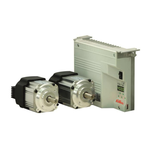
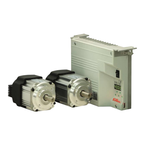
Efka DC 1550 User manual

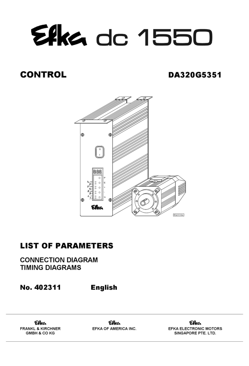
CONTROL AB320A5200
LIST OF PARAMETERS
CONNECTION DIAGRAM
TIMING DIAGRAMS
No. 402286 English
FRANKL & KIRCHNER EFKA OF AMERICA INC. EFKA ELECTRONIC MOTORS
GMBH & CO KG SINGAPORE PTE. LTD.
+
-
>>
P
E
0
I
KL2334a

EFKA AB320A5200
3
CONTENTS Page
1 Table of Adapter Cords 5
2 Putting into Service 6
3 Setting and Putting into Service with the Aid of the Fast Installation Routine (SIR) 7
4 Operating Elements and Socket Connectors 8
4.1 Position of Operating Elements and Displays 8
4.2 Position of the Socket Connectors 9
4.3 Connection Diagram 10
4.4 Connection of a Sewing Light with Transformer 13
4.5 Adapter Cords 14
5 Timing Diagrams 29
6 List of Parameters 56
6.1 Preset Values Depending on Mode 56
6.2 Operator Level 58
6.3 Technician Level 60
6.4 Supplier Level 65
7 Error Displays 78
8 Slide-in Strips for the V810/V820 Control Panels 79

EFKA AB320A5200
5
1 Table of Adapter Cords
Setting the functional sequence using parameter 290
Mode Designation Adapter Outputs
Power transistors !
!!
!FL VR M1 M2 M3 M4 M5 M6
ST2/35 ST2/34 ST2/37 ST2/28 ST2/27 ST2/36 ST2/32 ST2/30
0 Lockstitch; e. g. Functions FL VR FA1 FA2 FW FA1+2 ML MST
Brother (737-113, 737-913) 1112814 FL VR FA1 + FA2 FW
Aisin (AD3XX, AD158, 3310; EK1) 1112815 FL VR FA1 + FA2 FW
Pfaff (563, 953, 1050, 1180) 1112841 FL VR FA1 FA2 FW ML
Dürkopp Adler (210, 270) 1112845 FL VR FA1 + FA2 FW
2 Lockstitch; e. g. Functions FL VR FA FSPL FL1 ML MST
Singer (212 UTT) 1112824 FL VR FA FSPL FL1
3Lockstitch;e. g. Dürkopp Adler (467) FL VR FA FSPL FW ML MST
4 Chainstitch; e. g. Union Special Functions FL FA-R M1 FA-V FW STV ML
(34000 and 36200 replacement for US80A)1112865 FL FA-R FA-V FW ML
(CS100 and FS100) 1112905 FL FA-R M1 FA-V FW ML
5 Chainstitch; parallel sequence Functions FL STV M1 M2 M3 M4 ML MST
Bag sewing machine Union Special Functions FL IMP BR ML MST
Yamato (VC series) 1112818 FL STV FA FW
Yamato (VG series) 1113178 FL STV FA FW ML
Kansai (RX 9803) 1113130 FL FA FW ML
Pegasus (W500/UT, W600/UT/MS 1112821 FL STV FA FA FW
with or without stitch condensing)
Brother (FD3-B257) 1112822 FL STV FA FA FW
Union Special (34700) 1112844 FL STV FA FA FW NK
Global (CB2803-56) 1112866 FL FA
Rimoldi (F27) 1113096 FL FW FAO FAU ML
6 Chainstitch; tape cutter/fast scissors FL STV M1 M2 AH1 AH2 ML MST
7 Overlock FL KS M1 M2 AH FSPL ML MST
8 Backlatch Functions FL PD≤
≤≤
≤-1 PD≥
≥≥
≥1PD≥
≥≥
≥1* ML MST
Pegasus 1113234 PD≤-1 PD≥1
9 Backlatch Functions FL PD≤
≤≤
≤-1 PD≥
≥≥
≥1PD≥
≥≥
≥1* ML MST
Yamato (ABT3) 1112826 PD≤-1 PD≥1
Yamato (ABT13, ABT17) 1113205 PD≤-1 PD≥1
10 Lockstitch; e. g. Functions FL FA-R FSPL FA-V FW VR ML MST
Union Special (63900AMZ replacement 1112823 FL FA-R FA-V FW ML
for US80A) and on Refrey lockstitch machines
14 Lockstitch; e. g. Functions FL VR FA1+2 FA2 FW FA1 ML MST
Juki (5550-6) 1112816 FL VR FA1+2 FW
Juki (5550-7) 1113132 + FL VR FA1+2 FZ FW
(position sensor incorporated in the 1113157
handwheel)
15 Backlatch Pegasus (SSC100) FL KS/KB KB KS FSPL AH ML HP
16 Overlock; feed-off-the-arm machine e.g.Yamato (FD62) FL KS RB M2 AH FSPL ML MST
17 Chainstitch; Pegasus FL LFA FA STS ML
20 Lockstitch; Juki (LU1510-7) 1113200 FL VR FA FSPL ML MST
21 Chainstitch; Yamato (stitch lock) 1113178 FL STS FA STV FW ML
23 Lockstitch; Dürkopp Adler (271...275) FL VR FA ML FW FSPL HP MST
24 Chainstitch; Pegasus (MHG-100) 1113267 FL FA FA FW
*) The signal issued at this output is inverted!
ATTENTION!
Before switching functional sequences, detach cables from the inputs and outputs! Please ensure that the
machine installed provides the functional sequence to be set! Then proceed with the setting using parameter
290!

EFKA AB320A5200 6
Explanation of letter symbols of the previous page and chapter ”Timing Diagrams“
Outputs:
FL = Sewing foot lifting FL1 = Sewing foot lifting without pulsing
VR = Backtacking STV = Stitch condensing
FA = Thread trimmer FA1 = Thread trimmer pos. 1...1A
FA2 = Thread trimmer pos. 1A...2 FA1+2 = Thread trimmer pos. 1...2
FA-V = Thread trimmer forward FA-R = Thread trimmer backward
FAU = Bobbin thread trimmer FAO = Needle thread trimmer
FSPL = Thread tension release AH = Tape cutter
FW = Thread wiper AH1/AH2 = Fast scissors
ML/NK = Machine running / Needle cooling KS = Chain suction
RB = Chain blowing in opposite direction STB = Blow fabric onto stack
KB = Chain blowing KS+KB = Chain suction + blowing
MST = Machine at standstill HP/FF1 = High lift for walking foot /
PD≥1 = Pedal steps 1...12 flip-flop 1
PD=0 = Pedal step 0 PD≤-1 = Pedal steps –1 / -2
L-STL = Indicator lamp for stitch length PD-2 = Pedal step -2
FZ = Thread puller DR-UK = Reversal of motor direction
IMP = Impulse STS = Stitch lock
LFA = Top cover thread cutter BR = Hot thread chain cutting
2 Putting into Service
Before putting the control into service, the following must be ensured, checked and/or adjusted:
"The correct installation of the drive, position transmitter and accompanying devices, if necessary
"The correct selection of the trimming operation by means of parameter 290
"If necessary, the correct adjustment of the direction of motor rotation by means of parameter 161
"The correct selection of the functions of keys (inputs) by means of parameters 240...249
"The setting of the transmission ratio between motor shaft and machine shaft by means of parameter 272
"The setting of the type of position sensor by means of parameter 270
"If necessary, the setting of the number of angular degrees after the sensor position by means of parameter 271
"If necessary, the setting of the positions by means of parameter 171
(possible with all settings of parameter 270)
"The correct positioning speed by means of parameter 110
"The correct maximum speed compatible with the sewing machine by means of parameter 111
"The setting of the remaining relevant parameters
"Start sewing in order to save the set values
See instruction manual for details!

EFKA AB320A5200
7
3 Setting and Putting into Service with the Aid of the Fast Installation
Routine (SIR)
The Fast Installation Routine (SIR) passes through all parameters necessary for programming the functional sequence and
the positions.
Input parameter 500
Parameter for functional sequence “thread trimming operations”
Parameter for direction of motor rotation
Parameter for transmission ratio
Important! The transmission ratio should be
determined and indicated as precisely as possible.
Parameter for type of position sensor
Parameter for position 1
Parameter for position 2
The values can be varied by pressing the +/- keys. When the parameter is displayed on the V810 control panel, press
the E key once more for the value to be displayed.
Exit the routine any time by pressing the Pkey once, and select a new parameter. Exit programming by pressing the Pkey
twice, and the drive is ready for a new sewing operation.
See instruction manual for details!
F-272
End SIR
F-451
F-453
F-270
No
P
E
E
E
E
Yes
KL2438a
F-161
F-290
F-500
Code 3112
F-200
E
E
>>
E
E

EFKA AB320A5200 8
4 Operating Elements and Socket Connectors
4.1 Position of Operating Elements and Displays
S1 P key
"Call or exit programming mode
S2 E key
"Start backtack single / double / off
"Enter key for modifications in the programming mode
S3 + key
"End backtack single / double / off
"Increase of the value indicated in the programming mode
S4 – key
"Automatic sewing foot lifting at stop in the seam On/Off
"Automatic sewing foot lifting after thread trimming
On/Off
"Decrease of the value indicated in the programming mode
S5 >> key
"Basic position 1 or 2
"Shift key in the programming mode
LED1 Indicator for single start backtack
LED2 Indicator for double start backtack
LED3 Indicator for single end backtack
LED4 Indicator for double end backtack
LED5 Indicator for automatic sewing foot lift at stop
in the seam
LED6 Indicator for automatic sewing foot lift after
the thread trimming operation
LED7 Indicator for basic position “needle position 1“
LED8 Indicator for basic position “needle position 2“
Display 3 digits
AB320A5200
KL2472
LED4
LED5
LED6
LED7
LED8
Display
LED1
LED2
LED3
+
-
P
E
S4
S5
S1
S2
S3
0
I

EFKA AB320A5200
9
4.2 Position of the Socket Connectors
B2 Socket for sensors
B18 Socket for light barrier module
B41 Socket for motor power supply
B80 Socket for actuator
B776 Socket for V810/V820 control panel
ST2 Socket for solenoid inputs and outputs /
solenoid valves / displays / keys and switches
B41
M
B18
KL2333
ST2
L S M ...
B2
B41
B2
B18
M
B776
ST2
V8 . .
B80
B776
EB ...
B80

EFKA AB320A5200 10
4.3 Connection Diagram
Inputs switched to 0V
in1 - Input 1 i10 - Input 10 M9 - Output 9
in2 - Input 2 M1 - Output 1 M10 - Output 10
in3 - Input 3 M2 - Output 2 M11 - Output 11
in4 - Input 4 M3 - Output 3 FL - Sewing foot lifting
in5 - Input 5 M4 - Output 4 VR - Backtacking
in6 - Input 6 M5 - Output 5 POS1 - Position 1
in7 - Input 7 M6 - Output 6 POS2 - Position 2
in8 - Input 8 M7 - Output 7 GEN - 512 generator impulses
in9 - Input 9 M8 - Output 8 R-N-EXT - External potentiometer for
speed limitation (50kΩ)
ATTENTION!
When connecting the outputs, ensure that a total power of 96VA constant load will not
be exceeded!

EFKA AB320A5200
11
Inputs switched to +24V
1) Nominal voltage 24V, no-load voltage max. 30V momentarily after power on
2) Transistor output with open collector max. 40V, 10mA
3) Nominal voltage 15V, Imax = 30mA
4) Nominal voltage 5V, Imax = 20mA
*) Front view of the socket (component side) and/or rear view of the plug (soldering side)
ATTENTION!
When connecting the outputs, ensure that a total power of 96VA constant load will not
be exceeded!

EFKA AB320A5200 12
POS2 OUT - Output for position 2
POS IN - Input for positions
G1/G2 OUT - Output of generator impulses
TXD/RXD - Serial transmission lines
LSM IN - Possibility of connecting a light barrier module to socket B18/8
(If parameter 239 = 0, the light barrier function is selected.
Identification of the signal when switched to 0V.)
LSM002 - Reflection light barrier module
If parameter 239 is set to 1...43, a key can be operated on the input of socket B18/8.
+5V = Connect lefthand pins 1 and 2 with jumper (factory setting)
+15V = Connect righthand pins 3 and 4 with jumper
1) Nominal voltage +15V, 100mA (repluggable to +5V, 100mA)
2) Transistor output with open collector max. 40V, 10mA
*) Front view of the socket (component side) and/or rear view of the plug (soldering side)
B80
B2
B18
J4
1 3
2 4
+5V
J4
31
42
KL2351
+15V
J4
ATTENTION!
Before opening the cover, turn power off!

EFKA AB320A5200
13
4.4 Connection of a Sewing Light with Transformer
"Switch off the control and remove mains plug from outlet
"Unscrew the control unit from the machine table
"Loosen 4 screws (A)
"Remove the mounting plate
"Loosen 2 screws (B) each at the front and at the rear
"Open the left part of the housing
"Pull the sewing light cable through the cable bushing
"Area (C): Connect strands with clamp on the printed circuit board
"Insert earth lead into plug-in device on the housing part
"Close and screw-connect the housing
"Mount the control unit on the machine table
CAUTION!
When the sewing light is connected, it is always current-carrying (230V), even if
the control unit is switched off! Only one sewing light with transformer can be
connected to the control unit!
A
B
C
-
>>
+
P
E
KL2399
0
I
ATTENTION!
Before opening the cover, turn power off!

EFKA AB320A5200 14
4.5 Adapter Cords
Adapter cord for AISIN models AD3XX, AD158, 3310 and EK1
Setting the functional sequence Thread trimming mode !Set parameter 290 = 0
Setting the functions of the keys Input in1 !Set parameter 240 = 16
Input in3 !Set parameter 242 = 1
Adapter cord for BROTHER models 737-113 and 737-913
Setting the functional sequence Thread trimming mode !Set parameter 290 = 0
Setting the functions of the keys Input in1 !Set parameter 240 = 16
Input in3 !Set parameter 242 = 1
*) Rear view (soldering side) of 37-pin plug (ST2). Front view (component side) of the remaining plugs/sockets.
7 in1
37
20
19
SUB- D- 37
1
37 M1
35
VR
FL
34
28 M2
+24V26
27 M3
+24V
+24V
+24V
16
17
18
19 0V
ST2 Nr. 1112814
6 in3
1
40V
5
6
6
KL2233
24V
NHT
FL
0V
+
4
6
5
5
2
4
3
1
1
3
2
8
0V 12
12
FW
24V
ZVR
VR
24V
+
+
6
9
10
8
9
7
11
11 10
4
7
3
24V
FA1+ 2
+
4
52 1
1
2
3
Nr. 1112815
19 37
27 M3
37
35
34
FL
VR
28 M2
M1
SUB- D- 37
1
+24V
+24V
+24V
+24V26
20
16
17
18
19 0V
7 in1
1
40V
6 in3
ST2
3
+24V
VR
FW
+24V
2
32
4
3
11
3
4
0V
NHT
0V
FA1+ 2
+24V
ZVR
22
1
4
3
2
1
1
3
2
4
1
KL2234
+24V
FL 4
1
2
33
2
4
1

EFKA AB320A5200
15
Adapter cord for BROTHER model FD3 B257
Setting the functional sequence Thread trimming mode !Set parameter 290 = 5
Setting the functions of the keys Input in1 !Set parameter 240 = 7
Input in3 !Set parameter 242 = 18
Input in4 !Set parameter 243 = 16
Input in5 !Set parameter 244 = 17
*) Rear view (soldering side) of 37-pin plug (ST2). Front view (component side) of the remaining plugs/sockets.
Nr. 1112822
37
34
35 FL
VR
M1
1
19
SUB - D- 37
ST2
20
+ 24V
+ 24V
+ 24V
+ 24V
18
28 M2
37
26
27
19 0V
M3
17
16
in4
in17
8
+5V
0V
in36
in55
1
2
4
12
LSP
FL
+ 24V
6
5
4
2
3
1
5
4
6
KL2241
1
3
2
0V
+ 24V
FA
FA
+ 24V
+ 24V
STV
FW
5
10
11
6
8
9
76
9
12
4
3
1
2
7
3
5
+5V
STVU
ENTK
LSP
ZSTV
0V
4
6
5
2
4
2
3
1
1011
5
84
7
2 1
37
6
1

EFKA AB320A5200 16
Adapter cord for DÜRKOPP ADLER models 210, 270
Setting the functional sequence Thread trimming mode !Set parameter 290 = 0
Setting the functions of the keys Input in1 !Set parameter 240 = 16
Input in3 !Set parameter 242 = 1
Input in4 !Set parameter 243 = 3
Input in5 !Set parameter 244 = 17
Adapter cord for GLOBAL model CB2803-56
Setting the functional sequence Thread trimming mode !Set parameter 290 = 5
Setting the functions of the keys Input in1 !Set parameter 240 = 6
*) Rear view (soldering side) of 37-pin plug (ST2). Front view (component side) of the remaining plugs/sockets.
19 37
SUB - D- 37
37 M1
35 FL
28
34 VR
M2
20 POS1
27 M3
16
18
19 0V
+ 24V
+ 24V
120
ST2
Nr. 1112845
7
8
in1
in4
4
5
6
1
in5
in3
0V
6
KL2259a
ZVR
EST
7
4
5
6
537
10
NHT
0V
VRU
FA1+ 2
VR
FL
1
2
32
4
8
9
16
2
345
1
POS1
+24V 7
6
0V
FW
4
5
1
2
3
10 7
8
9
Nr. 1112866
19
SUB - D- 37
1
ST2
+ 24V
+ 24V
37 35 FL
37
20
27 M3
17
18
7 in1
1
40V
3
12
24V
0V
FL
LSP
+
12
6
10
6
8
9
7
11
9
24V
FA
+
4
5
1
2
3
KL2301
11
54
7
10
8
2 1

EFKA AB320A5200
17
Adapter cord for JUKI model 5550-6
Setting the functional sequence Thread trimming mode !Set parameter 290 = 14
Setting the functions of the keys Input in1 !Set parameter 240 = 16
Adapter cord for JUKI model 5550-7
Setting the functional sequence Thread trimming mode !Set parameter 290 = 14
Setting the functions of the keys Input in1 !Set parameter 240 = 16
*) Rear view (soldering side) of 37-pin plug (ST2). Front view (component side) of the remaining plugs/sockets.
**) Front view (component side) of the Molex Minifit plugs.
Nr.
1112816
37 M1
40V
SUB - D- 37
19
1
+ 24V
27 M3
37 34
35
VR
FL
26
+ 24V
+ 24V
+ 24V
20
16
17
18
11 in2
ST2
1
KL2235b
3
11FA1+ 2
12
+24V
FL
2
1
2
1
2
11
10
+24V
+24V
VR
+24V
FW
6
8
9
76
9
12
4
53
7
10
1
54
8
ZVR
0V
1
2
Nr.
1113132
19
1
SUB - D- 37
M228
M1
+ 24V
VR
FL
37
37 34
35
33
+ 24V16
M3
+ 24V
+ 24V
0V
+ 24V
20 17
18
19
27
26
ST2
in2
1
11
ZVR 5
+ 24V 13
+ 24V
FL
14
2
11 2
KL2363
VR 67
+ 24V
+ 24V
+ 24V
0V 12
10
8
9
7
11 1
2
3
4
5
614
11
10
13
12
9
8
FA1+ 2
FW
FZ 4
2
3
1

EFKA AB320A5200 18
Adapter cord for JUKI model LU1510-7
Setting the functional sequence Thread trimming mode !Set parameter 290 = 20
Setting the functions of the keys Input in1 !Set parameter 240 = 13
(Automatic setting) Input in3 !Set parameter 242 = 31
Input in4 !Set parameter 243 = 32
Input in6 !Set parameter 245 = 16
Input in7 !Set parameter 246 = 13
in1 = Input high lift for walking foot with speed limitation n10 (operational mode not stored) for knee switch
in3 = Input speed limitation bit 0 (S1)
in4 = Input speed limitation bit 1 (S2)
in6 = Input intermediate backtack
in7 = Input high lift for walking foot with speed limitation n10 (operational mode not stored) for additional
pushbutton at the machine head
*) Rear view (soldering side) of 37-pin plug (ST2). Front view (component side) of the remaining plugs/sockets.
**) Front view (component side) of the Molex Minifit plugs.
37
34
35
33
30
10
15
+ 24V
FL
M1
+ 24V
VR
FL
M6
+ 24V
0V
S2
HP in
2
1
KL2437
1 2
6 4
9
12
15
8
9
7
87
10
13
14
11
6
5
5
SUB - D- 37
19 19
37
28
26
18
17
1
16
9
12
20 8
6
ST2
1
4
14
13
12
10
11
0V
M2
+ 24V
+ 24V
+ 24V
FSPL
+ 24V
0V
S1
HPout
+ 24V
in7
in6
in4
in3
+ 24V
0V
+ 24V
VR
ZVR
4
2
3
1
321
8
9
7
6
5
512
1
2
3
411
9
8
10
6
713
14
Nr. 1113200
0V
FA
4
2
3
1

EFKA AB320A5200
19
Adapter cord for KANSAI model RX9803
Setting the functional sequence Thread trimming mode !Set parameter 290 = 5
Setting the functions of the keys Input in1 !Set parameter 240 = 7
*) Rear view (soldering side) of 37-pin plug (ST2). Front view (component side) of the remaining plugs/sockets.
Nr. 1113130
19
1
M327
M5
FL
M1
37
37
35
32
SUB- D- 37
+24V
+24V
+24V
+24V
in1
26
20
16
17
18
7
ST2
0V
+5V
4
2
1
+24V
FL
2
1
3
43
2
1
4
+24V
+24V
+24V
ML
FA
FW
6
4
2
3
1
54
5
6
KL2362
1
2
3
0V
+5V
LSP
33
1
22
1

EFKA AB320A5200 20
Adapter cord for PFAFF models 563, 953, 1050, 1180 without thread monitor
Setting the functional sequence Thread trimming mode !Set parameter 290 = 0
Setting the functions of the keys Input in4 !Set parameter 243 = 12
Input in5 !Set parameter 244 = 16
*) Rear view (soldering side) of 37-pin plug (ST2) and of the remaining sockets.
KL2261
37 M1
19 37
SUB - D- 37
120
ST2
26 + 24V
34 VR
35 FL
27
28
32
M3
M5
M2
16
17
19
18
8
+ 24V
+ 24V
in4
0V
+ 24V
Nr. 1112841
4
1
5in5
0V
4
VR
+ 24V
ZVR
0V
0V
VR
+ 24V
ZVR
ML
4
1
2
3
2
3
4
1
2
3
6
3
2
1
4
4
5
1
4
2
2
0V
FW
+ 24V
+ 24V
FA1
FA2
FW
+ 24V
+ 24V
FA1
FA2
6
4
53
1
2
3
5
1
2
3
43
1
2
FL
+ 24V
+ 24V
0V
FLEX
VR
5
6
6
4
1
2
3
4
5
6
1
3
6
1
5

EFKA AB320A5200
21
Adapter cord for PEGASUS models W500/UT, W600/UT/MS with or without stitch condensing
Setting the functional sequence Thread trimming mode !Set parameter 290 = 5
Setting the functions of the keys Input in1 !Set parameter 240 = 7
Attention! When using this adapter cord on a Pegasus machine, the 9-core cable no. 742373-91 must be
removed from the machine!
Adapter cord for PEGASUS backlatch machines
Setting the functional sequence Thread trimming mode !Set parameter 290 = 8
Setting the functions of the keys Input in1 !Set parameter 240 = 6
(Automatic setting) Input in3 !Set parameter 242 = 10
*) Rear view (soldering side) of 37-pin plug (ST2). Front view (component side) of the remaining plugs/sockets.
Nr. 1112821
37 M1
19
1
SUB - D- 37
ST2
+24V
+24V
+24V
+24V
+24V
27 M3
35 FL
37
33
34 VR
28 M2
20 17
18
19 0V
16
26
1
2+5V
7 in1
+24V
STV
2
11
2KL2240
2
8
LSP
0V
+24V
FL
+24V
+5V
2
3
2
1
2
1
2
1
6
8
9
7
1
9
6
+24V
+24V
FW
FA
FA
43
5
1
2
3
7
54
1
Nr. 1113234
37 M1
19
1
SUB - D- 37
37
20
ST2
0V
4
28 M2
19 0V
6
7
in3
in1
1
0V 2
KL2458
2
3
2
3
2
1
4
0V
Ped -1
=
5
6
1
4
0V
N-AUTO
LSP
6
2
3
1
5
5
1
4 1
6
6
5
1
=
Ped
1
2
3
Ped -1
=4

EFKA AB320A5200 22
Adapter cord for PEGASUS model MHG
Setting the functional sequence Thread trimming mode !Set parameter 290 = 24
Setting the functions of the keys Input in1 !Set parameter 240 = 6
Input in2 !Set parameter 241 = 13
Input in3 !Set parameter 242 = 28
Input in4 !Set parameter 243 = 22
*) Rear view (soldering side) of 37-pin plug (ST2). Front view (component side) of the remaining plugs/sockets.
Nr.1113267
33 +24V
KL2482
35
37
FL
M1
37
20
SUB- D- 37
19
1
ST2
25
26
27
28
32
+24V
M3
M2
M5
M9
15
16
17
18
19
23
+15V
0V
+24V
+24V
+24V
M7
0V4
11
8
7
6 in3
in1
in4
in2
1
2+5V
+24V
1
2
3
4
5
6
+24V
+24V
M9
in2
0V
M7
2
1
2
1
+24V
FL
M5
2
3
1
5
6
4
2
1
2
1
2+24V
2
3
1
LSP
+5V
0V
3
4
5
6
7
8
9
+24V
+24V
FW
FA
1
2
3
1
+15V
SEN
0V
FA
1
2
in4
0V
1
2
3
654
79 8
23 1
2
2
1
3
1
Other manuals for DC 1550
2
This manual suits for next models
1
Table of contents
Other Efka Control Unit manuals
Popular Control Unit manuals by other brands

Tideflex
Tideflex 37 Series Installation, operation and maintenance manual

Ekinex
Ekinex EK-MC1-TP user manual

Moog
Moog D636 Series Mounting and Installation Notes

Parker Pneumatic
Parker Pneumatic V-650P Installation & service instructions

ASCO Valves
ASCO Valves 327C Series Installation & maintenance instructions

Siemens
Siemens VVF Series Mounting instructions