WEISS FV663 Installation instructions

Product Code: ER12C-3
INSTALLATION/OPERATION INSTRUCTIONS FV663-FV604
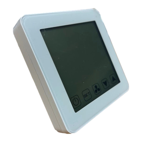
HEAT TRANSFER CONTROLLER
Mode
Fan speed adjust
Power ON/OFF
Set Comfort Temperature Up
Set Comfort Temperature Down
For your safety please follow the installation and operating instructions

© COPYRIGHT Weiss Ltd 2019. All rights reserved
Weiss Limited reserves the right to alter designs and specifications
without notice and without obligation
ER12C-3
Revision 02.0 140319
GENERAL USE AND SAFETY INFORMATION
Thank you for purchasing this quality DIGITAL HEAT TRANSFER CONTROLLER by Weiss.
This digital controller has been designed to ensure highly effective transfer of heated air throughout your
home. The large screen is designed for easy and straightforward setup of your heat transfer system, using a
high precision built-in sensor with custom sensing algorithm to accurately determine room temperature and
improve system stability.
The controller constantly monitors the room and set temperatures. When the heat source provides heat to
the room and raises the room temperature above the set temperature, the controller will detect this increase
and switch the fan to the desired speed. The user can switch between manual speed, or automatic speed,
allowing the controller to automatically adjust the fan speed to best make use of the available heat.
NOTE: THESE UPDATED INSTALLATION AND OPERATION INSTRUCTIONS SUPERSEDE ANY INSTRUCTIONS ON THE
CARTON or other FITTING INSTRUCTIONS
PLEASE READ ALL INSTRUCTIONS CAREFULLY BEFORE COMMENCING INSTALLATION.
Note: Pictures and diagrams on packaging are designed only to be used as a concept. All installation
details should be carried out as per the instructions herein.
Note:THIS PRODUCT MUST BE WIRED BY A REGISTERED ELECTRICIAN
SUITABILITY
The controller constantly monitors the room and set temperatures. When the heat source provides heat to
the room and raises the room temperature above the set temperature, the controller will detect this
increase and switch the fan on.
BEFORE YOU START
Weiss DIGITAL HEAT TRANSFER CONTROLLER must not be mounted in areas subject to direct splashing. Refer
to New Zealand standard NZECP2: 1988 Section 4.6 and Australian Standard AS3000:1991, Section 6.2.
SAFETY NOTE
This appliance is not intended for use by persons (including children) with reduced physical, sensory or
mental capabilities, or lack of experience and knowledge, unless they have been given supervision or
instruction concerning use of the appliance by a person responsible for their safety. Children should be
supervised to ensure that they do not play with the appliance.
To avoid a hazard, a damaged supply cord must be replaced by the manufacturer. This includes the
removal of the supply cord as this appliance is supplied as compliant. Modification including removal of the
plug or cutting of the supply cord (fitted to any motor) will render unit NON-COMPLIANT.
INSTALLATION INFORMATION
IMPORTANT
Selecting the mounting location
•The controller is for internal use only.
•Mount approx. 1.5 metres above the floor on an inner wall near the heat source.
•The controller must be placed within the same room as the heat source.
•Avoid locations which are not affected by the heat source, e.g. other side of the room or around a
corner.
•Do not mount on hot surfaces or surfaces exposed to direct sunlight.
FOR OPTIMUM PERFORMANCE –Installation Instructions
1. Open the controller by pushing in the tabs located on the bottom of the unit (figure 1a and 1b)
and remove the interconnect cable.
2. Choose a mounting position on the wall and cut a 64 mm diameter hole in the wall gib,
avoiding any structure timber framing.
3. See Wiring Diagrams below to connect the fan.
4. After connecting the required wiring, mount the base of the controller with the 4 screws provided
(figure 2), noting the top direction.

© COPYRIGHT Weiss Ltd 2019. All rights reserved
Weiss Limited reserves the right to alter designs and specifications
without notice and without obligation
ER12C-3
Revision 02.0 140319
5. Reconnect the interconnect cable to the display front.
6. Replace the cover by locating the two tabs at the top of the unit and lever the touch screen on
as shown (figure 3). As you close the unit ensure the two plastic tabs at the bottom clip into
place.
Note: Do not use excessive force to fit the cover.
HOW TO CONNECT UP A WEISS ER12C-3 DIGITAL CONTROLLER
1. The active line in is connected to terminal 7 at the rear of the control unit.
2. The active lines out to the fan unit are terminals 2,3,4 at the rear of the control unit.
3. Neutral connections are common to terminal 1 at the rear of the control unit.
4. The controller is then set to the temperature that is required to be maintained in the room with the
main heat source (the room with the controller) using the up and down arrows to modify the smaller
number (top right of display).
FINAL STEPS
Finally, connect the wiring as illustrated in the wiring diagram above.
Note: Approximate means of disconnection are required to be incorporated in the fixed wiring. This product
must be installed by registered Electrician.
Display information
Power OFF System is Off. The fan will be switched off and the controller switches to standby mode.
Set Minimum Room Temperature –The controller adjusts the heat transfer rate according to the set
temperature. Adjust the set temperature using the Adjust Up and Down buttons.
Mode As a Heat Transfer specific controller, this controller is locked into Heat Transfer mode
and cannot be switched to an alternative mode.
Setting Heat Transfer Speed
Adjust the set speed with the Fan Speed Adjust button. The speed will cycle through the following
options:
High speed - Fan will operate at high speed only. High speed is activated when the room temperature exceeds the set
temperature.
Medium - Fan will operate at medium speed only.
Low - Fan will operate at low speed only.
Auto - Controller selects Low, Medium or High speed depending on the difference between the room temperature
and your set temperature.
ADVANCED CONTROLLER FUNCTIONS
Locking the controller
To lock/unlock the controller press and hold the Adjust Up and Down buttons together.
The lock symbol appears in the middle-left of the display when locked
Entering Advanced set-up
•Turn off your controller with the Power Off button.
•Press and hold the Fan Indicator button for 5 seconds.
•Switch between set-up screens using the Fan indicator button
•Press the Power Off button to return to the home screen
`
LOW
7
6
5
4
3
2
1
Neutral
FAN

© COPYRIGHT Weiss Ltd 2019. All rights reserved
Weiss Limited reserves the right to alter designs and specifications
without notice and without obligation
ER12C-3
Revision 02.0 140319
•The controller will turn off after 5 seconds of no activity in programming mode
COMPLIANCE AND WARRANTY INFORMATION
•This appliance must be installed by a registered electrician in accordance with the relevant electrical
wiring rules and regulations and a COC is required for a warranty claim.
•Not for use with a heat pump
•Do not cover the fan unit with any insulation material
•Do not completely close off adjustable outlet vents
•Always install this product with the supplied controller
•Weiss Limited reserves the right to alter designs and specifications without notice
•Incorrect wiring or installation is not covered by warranty
•Full Warranty information is available on our web site: https://www.weiss.co.nz/warranty
QUESTIONS AND ANSWERS
Can I place the controller in a different room from the fireplace/heat source?
No. The controller must be mounted in the same room as your heat source. Make sure that the controller is
in a position where it can easily detect changes in the room temperature from your heat source, e.g. 2-4
metres away from the heat source. Do not place the controller in the hallway or near the doorway, around
a corner from the heat source, or far away (>6 metres) from the heat source in a large room.
How far away from the heat source should I place the fan?
You should keep at least 1.5 metres of distance between the heat source extraction point and the fan.
However, the recommended distance between the extraction point and the fan is 3 metres.
IMPORTANT NOTES
Technical Specifications
Set Temperature Range: 5 - 35°C
Temperature Resolution: 0.5°C
Operating Voltage/Frequency: 230VAC 50Hz
Sensing Element: NTC thermistor
Operating Temperature: 0 to 40ºC
Operating Humidity: 5 - 90% non-condensing
Output Control: Digital control interface
Display: 3.5” digital LCD Touchscreen
Approval: All relevant AS/NZS standards
EMC Approval: All relevant AS/NZS standards
•The unit should be checked annually for correct operation.
•This controller has been designed to work with Weiss Heat Transfer AC Fans only.
Weiss Limited, 20b Arwen Place, East Tamaki
PO Box 204-120 Highbrook Auckland
New Zealand
Web: www.weiss.co.nz
Advanced set-up screens
1. Temperature calibration: adjust with the Adjust Up and Down
buttons
2. Maximum operating temperature (not used): default value 25°C
3. Minimum operating temperature (not used): default value 20°C
This manual suits for next models
2
Table of contents
Other WEISS Controllers manuals
Popular Controllers manuals by other brands

Advanced Electronic Applications
Advanced Electronic Applications PK-88 operating manual

esera automation
esera automation Auto-E-Connect 11340 user guide

MacroAir Technologies
MacroAir Technologies Controller 30 Operation manual

ARIS
ARIS TENSOR Quick manual

ARZAMAN
ARZAMAN SmartPID SPC1000 user manual

Graco
Graco 24F472 Operation