OPERATING INSTRUCTIONS FOR GAMBIT DAC1-MK2 24Bit / 192kHz D/A CONVERTER OPERATION
Daniel Weiss Engineering Ltd., Florastr. 42, CH-8610 Uster Page 4of 8
)+41 1 940 20 06 2+41 1 940 22 14 8http://www.weiss.ch / http://www.weiss-highend.com
OPERATION
Input Source Selection
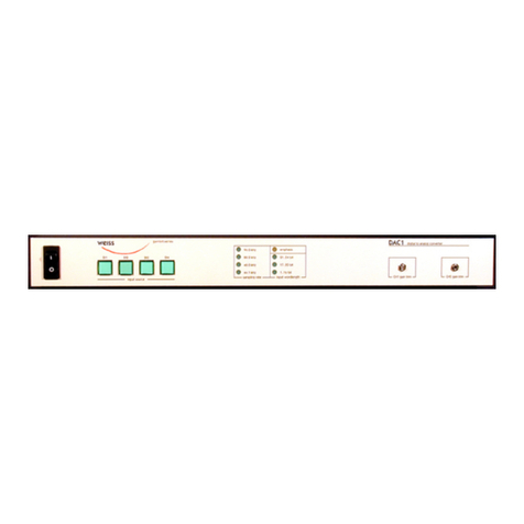
The input source pushbuttons correspond to the
three XLR and the single Toslink input connec-
tors.
If a valid AES/EBU or S/PDIF formatted signal is
present at the selected input, its sampling rate,
wordlength and emphasis status are indicated via
the status LEDs.
The wordlength LEDs are blank if the input signal
is muted.
If the sampling rate is valid, the analog outputs
are activated. Blank sampling rate LEDs indicate
that the format or sampling rate at the input are
not valid. In that case the analog outputs are
muted.
For 176.4 or 192kHz signals the two channels are
connected as follows: Left channel to input 1,
Right channel to input 2. To activate, press the
input 1 key. If such a signal is present at the input
of the DAC1-MK2, the software automatically
detects that and switches the D/A accordingly.
Also both input 1 and input 2 keys are lit. If you
press the input 2 key with such a two wire signal
present at inputs 1 and 2, the DAC1-MK2 inter-
prets the signal at input 2 as a normal two chan-
nel AES/EBU signal. I.e. do not select input 2
when feeding a two wire signal.
For the three XLR inputs a corresponding XLR
output is available. These outputs are buffered
clones of the input signals. The purpose is to loop
in the DAC1 at various points in the signal chain
for monitoring.
For the third output (DO3) the source can be
selected to be either Input 3 (DI3) or the cur-
rently selected input. This allows to use the
DAC1 as a monitor switch.
Synchronization
The DAC1 is always slaved to the selected input.
Because the jitter reduction circuitry in the DAC1
is of the highest possible quality, sepaarate exter-
nal or internal synchronization is not necessary.
For applications in surround setups with more
than one DAC1 unit operating in parallel, we will
offer a software version which assures a deter-
mined, constant delay from input to output. In
the current software version this is not the case,
i.e. the delay from input to output can vary.
The states of all buttons are stored in non-volatile
memory, i.e. the setup is retained when powering
the unit off.
Output Level and Output Con-
nection
The output level is set via the "high / low" switch
on the backpanel and via the trim potentiometers
on the frontpanel. For output levels between
+15dBu and +27 dBu balanced (or +9dBu and
+21dBu unbalanced) set the switch to "high". For
all other levels set it to "low". These output level
figures are reached for 0dBFS at the input of the
DAC1.
After that, adjust the trim potentiometers to
match the output level required.
Note that the output amplifiers of the DAC1 are
powerful class A type discrete circuits. This
means that the power dissipation is quite high, so
it is absolutely normal for the DAC1 unit to heat
up.
Important: For unbalanced operation of the
DAC1 connect pin 1 (ground) and pin 2
(hot) of the output connectors to your am-
plifier. Pin 3 must be left open!


