OPERATING INSTRUCTIONS FOR GAMBIT ADC2 24Bit / 192k z A/D CONVERTER OPERATION
Daniel Weiss Engineering Ltd., Florastr. 42, CH-8610 Uster Page 4 of 4
+41 1 940 20 06 +41 1 940 22 14 http://www.weiss. h weiss@weiss. h
Digital In
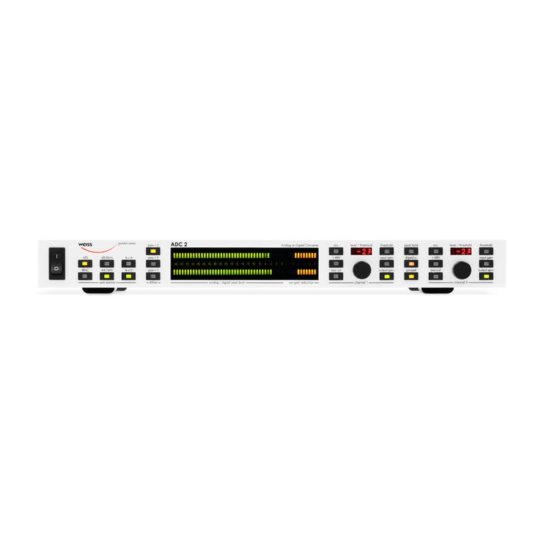
Pressing the “digtial in” key a tivates the digital
AES/EBU XLR input, the key lights red if a tive.
As soon as a valid signal is present, the sampling
rate is displayed with the sampling rate keys (see
Fig. 6).
If the digital input stage does not lo k to any sig-
nal, none of the sampling rate keys are lit.
If the “digital in” key is not lit, the analogue inputs
are sele ted. To a tivate the mi rophone input
for either hannel, press the appropriate “mic”
key (if “ganged” is a tive, pressing one “mic” key
will sele t mi rophone inputs for both hannels).
Press “+48 ” if phantom power is needed.
It is usually advisable to use “low-cut” when re-
ording with mi rophones. If “low-cut” is lit, low
frequen y ontent (traffi rumble, building trem-
ors, air- ondition hum and other low-frequen y
air movement like doors opening or losing near
the mi rophone et .) is filtered out.
Peak old
If “peak hold” is lit, the numeri display shows the
peak hold value (in dBFS) whi h is sele ted by the
gain key: “input gain” sele ts the input peak hold,
“output gain” sele ts the output peak hold
(“threshold” also sele ts output peak hold). See
Fig. 1 for positioning of input and output peak
hold in the pro essing hain.
If input peak hold is sele ted, values equal to or
above 0.0dBFS are indi ated by “>=0”. The
output peak hold however an measure values
above 0.0dBFS be ause of the internal floating-
point data format used in the digital signal pro -
essor. This is very useful to set the output gain.
To clear the peak hold value, double-click
the “peak hold” key!
Double- li k resets both input and output peak
hold.
Input Gain
If “input gain” is lit, the rotary knobs ontrol the
analogue input sensitivity. This is adjusted in 1dB
steps via a relais ontrolled attenuator. The se-
le ted value is shown in the numeri display.
The level bargraph is swit hed between input and
output in the same manner as the peak hold.
Thus, if the “input gain” key is lit, the bargraph
displays the input peak meter. If the “output gain”
key is lit, the bargraph displays the ouput peak
meter (settings an be different if “ganged” is not
lit).
Refer to Fig. 1 on p. 3 for positioning of input and
output peak meter in the pro essing hain.
Note: The referen e for the input sensitivity
display an be hosen by the user. For that pur-
pose press and hold the “ganged” key and then
swit h the ADC2 on. After a few se onds release
the ganged key. Wait for a few more se onds.
Now you an sele t the referen e with the
righthand knob. This allows to set the referen e
to e.g. +4dBu. Fa tory setting is 0 dBu referen e.
When finished press the blinking “peak hold” key.
The setting is retained in non-volatile memory.
Output Gain
If “output gain” is lit, the rotary knobs ontrol the
digital output gain. This gain an be used for op-
timal gain adjustment and to drive the peak lim-
iter (see below).
The gain ranges from -∞ (off) to +18.0 dB, the
resolution is optimized for fine ontrol around 0.0
dB while still allowing omplete fade-out. A spe-
ial algorithm is used for li k-free gain transis-
sions (no “zipper” noise).

