Page 2 Page 3
105871 - WTS-200 11.06.2019 105871 - WTS-200 11.06.2019
Contents Appliance description
The WTS-200 is a universal tank control unit combining a modern milk
cooling regulator and a complete cleaning programme control system in
one.
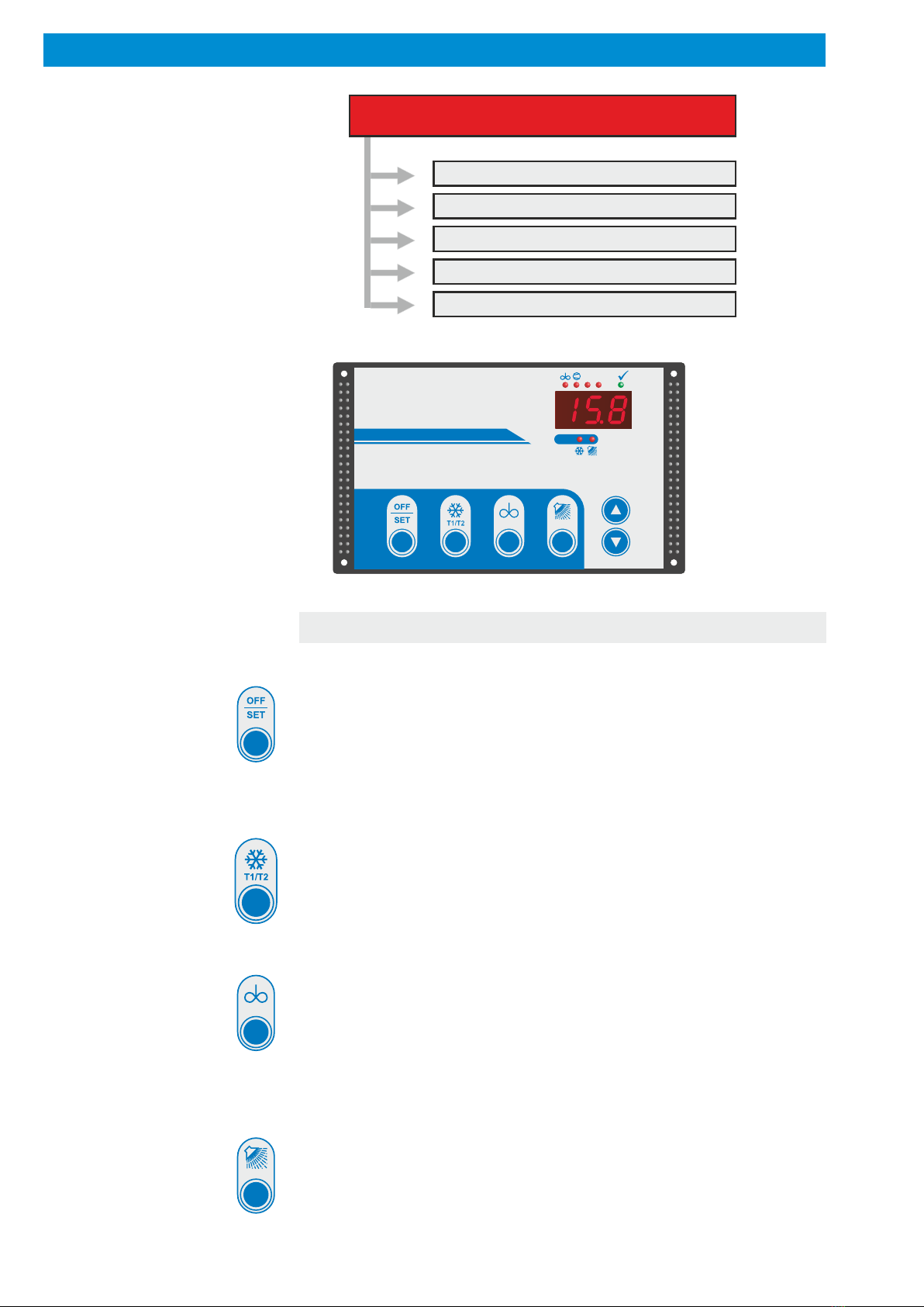
The control unit has various operating modes:
!OFF mode (with continuous stirring function)
The control unit is on stand-by. The display shows 'OFF', the LEDs
are out and all output replays are deactivated.
In the OFF mode the agitator can be switched on and off by press-
ing a button. In parameter [C25] can be set after which time the
agitator switches off automatically.
The following operating modes can only be selected from the OFF
mode. It is not possible to switch directly from one of them to
another.
CAUTION: The control unit is live even when switched off.
!Cooling mode
The current milk temperature, as measured, is permanently
displayed.
It is possible to switch between two freely adjustable target temper-
atures by pressing a button. If the milk temperature exceeds the
selected target temperature (T1 or T2) by the hysteresis value, the
compressor relay and agitator are automatically activated. Once
the target temperature is reached, the compressor switches off,
while the agitator continues to operate for the pre-set 'after-stirring'
time.
During non-cooling periods the agitator switches on at pre-set
intervals in order to ensure an even temperature throughout the
milk.
Independently of this a short or long 'intermediate stirring' period
can be selected during cooling by pressing a button.
Start cooling mode by pressing button on foil keyboard:
If the delayed start is activated (parameter [P62]), cooling starts for
the first milking after a delay. If the cooling button is pressed twice,
cooling starts immediately.
Start cooling mode via digital input:
The cooling starts immediately - depending on the setting in
parameter [C79] - or with a delayed start cooling.
!cleaning mode
The cleaning timer controls water intake as either by time or level,
selected. All running times (heater, pump, detergent injection) can
be set separately. Detergent switchover from alkaline to acidic can
also be set.
The WTS-200 controls the various processes and times needed
for a thorough wash fully automatically.
Following a power failure the control unit restarts in the mode
in which it was operating before the outage.
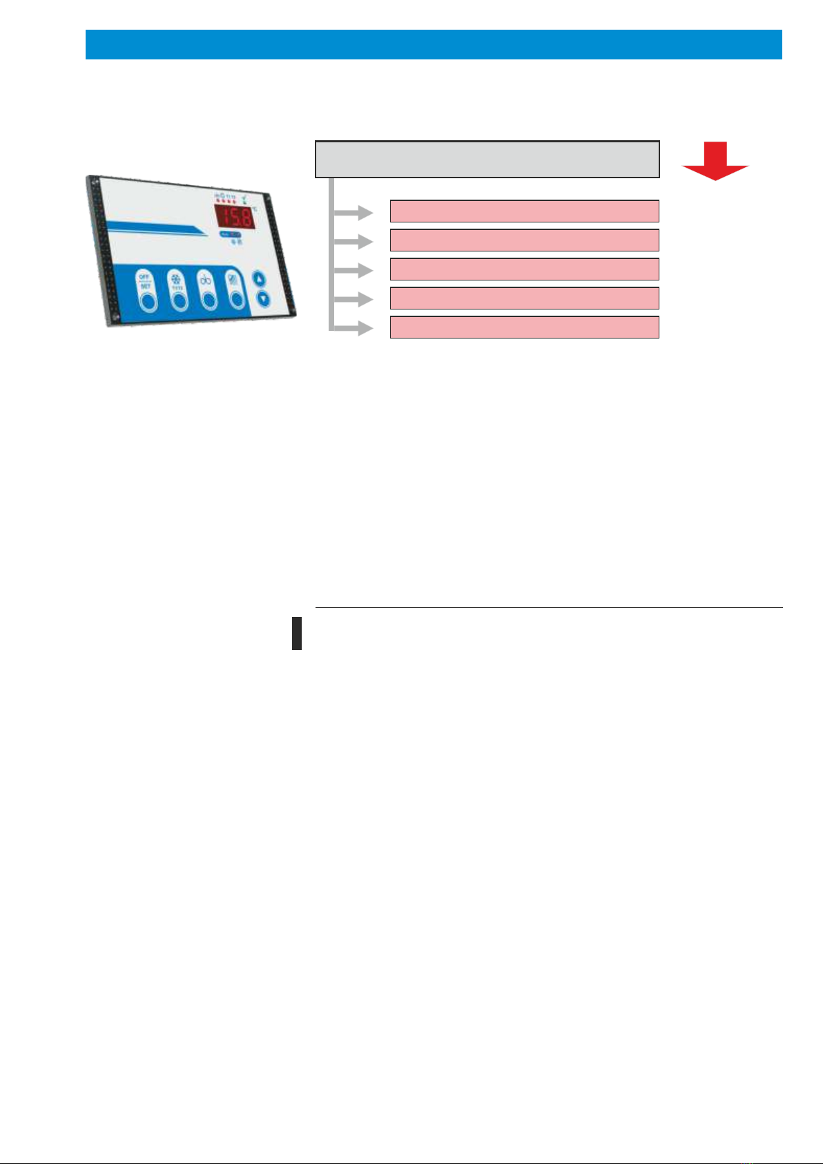
Appliance decription . . . . . . . . . . . . . . . . . . . . . . . . . . . . . . . . . . . . . . . . . 3
Safety .....................................................4
- Intended use . . . . . . . . . . . . . . . . . . . . . . . . . . . . . . . . . . . . . . . . . . . . 4
Installation .................................................5
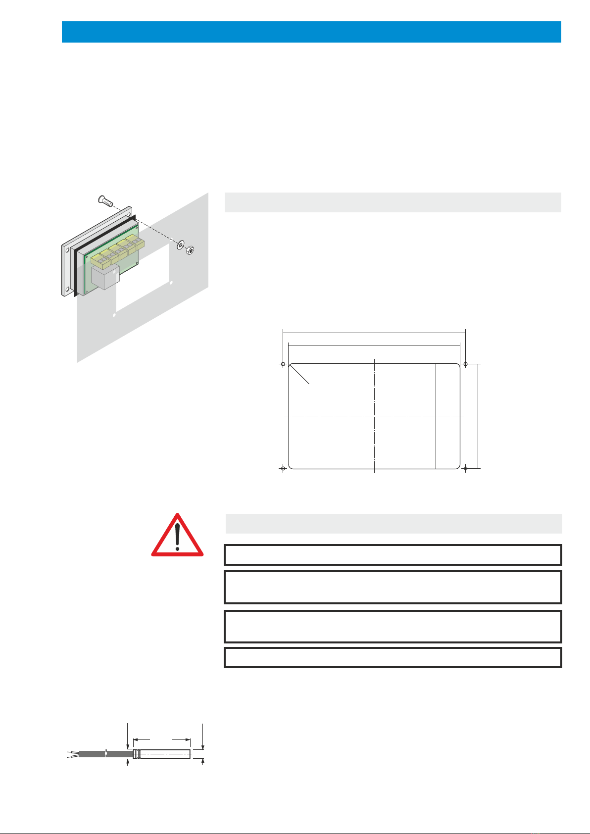
- Installation of housing . . . . . . . . . . . . . . . . . . . . . . . . . . . . . . . . . . . . . 5
- Fitting the sensor. . . . . . . . . . . . . . . . . . . . . . . . . . . . . . . . . . . . . . . . . 5
- Electrical connection . . . . . . . . . . . . . . . . . . . . . . . . . . . . . . . . . . . . . . 6
- Connection diagramm . . . . . . . . . . . . . . . . . . . . . . . . . . . . . . . . . . . . . 7
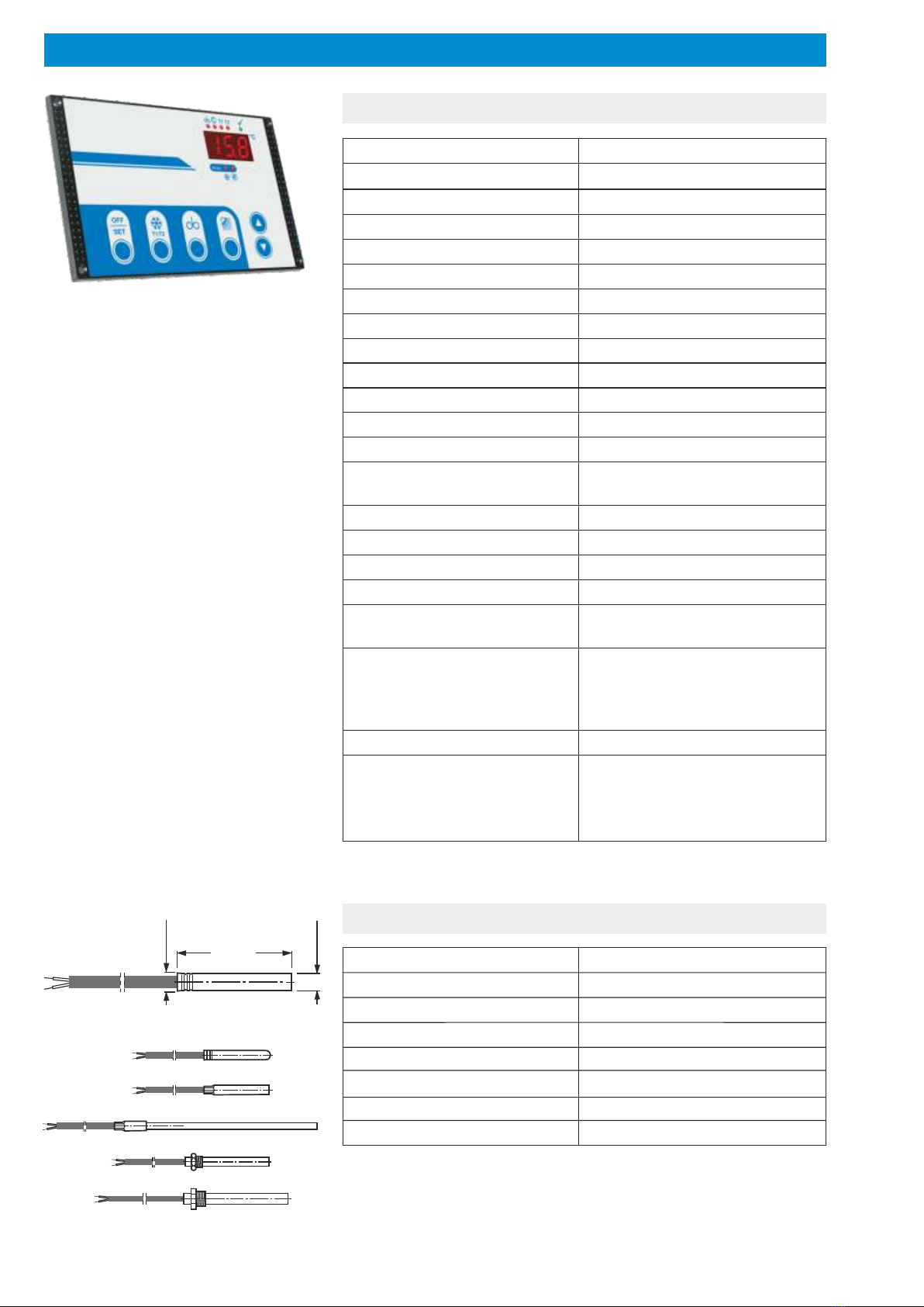
Technical data ..............................................8
- Control. . . . . . . . . . . . . . . . . . . . . . . . . . . . . . . . . . . . . . . . . . . . . . . . . 8
- Sensor . . . . . . . . . . . . . . . . . . . . . . . . . . . . . . . . . . . . . . . . . . . . . . . . . 8
Operating levels .............................................9
Operation of working level . . . . . . . . . . . . . . . . . . . . . . . . . . . . . . . . . . . 10
- Button functions. . . . . . . . . . . . . . . . . . . . . . . . . . . . . . . . . . . . . . . . . 10
- Meaning of LEDs . . . . . . . . . . . . . . . . . . . . . . . . . . . . . . . . . . . . . . . . 11
- Operating modes. . . . . . . . . . . . . . . . . . . . . . . . . . . . . . . . . . . . . . . . 12
Cleaning programme description. . . . . . . . . . . . . . . . . . . . . . . . . . . . . . 14
- Cleaning programme diagramm . . . . . . . . . . . . . . . . . . . . . . . . . . . . 14
- Cleaning stage 1 -> Pre rinse 1. . . . . . . . . . . . . . . . . . . . . . . . . . . . . 15
- Cleaning stage 2 -> Main rinse 2. . . . . . . . . . . . . . . . . . . . . . . . . . . . 16
- Cleaning stage 3 -> Main rinse 1. . . . . . . . . . . . . . . . . . . . . . . . . . . . 17
- Cleaning stage 4 -> Intermediate rinse . . . . . . . . . . . . . . . . . . . . . . . 18
- Cleaning stage 5 -> Main rinse 2. . . . . . . . . . . . . . . . . . . . . . . . . . . . 19
- Cleaning stage 6 -> After rinse . . . . . . . . . . . . . . . . . . . . . . . . . . . . . 20
- Cleaning with alkaline or acidic detergent . . . . . . . . . . . . . . . . . . . . . 21
- Time of dosing . . . . . . . . . . . . . . . . . . . . . . . . . . . . . . . . . . . . . . . . . . 21
- Faults during cleaning process . . . . . . . . . . . . . . . . . . . . . . . . . . . . . 22
- Manual stop of the cleaning process. . . . . . . . . . . . . . . . . . . . . . . . . 22
- Power failure during the cleaning process. . . . . . . . . . . . . . . . . . . . . 23
- Service functions for testing the cleaning cycle. . . . . . . . . . . . . . . . . 23
Adjustment of parameters in general. . . . . . . . . . . . . . . . . . . . . . . . . . . 25
Operation of 'General cooling parameters' level. . . . . . . . . . . . . . . . . . 26
Operation of 'Extended cooling parameters' level . . . . . . . . . . . . . . . . 28
Operation of 'General cleaning parameters' level. . . . . . . . . . . . . . . . . 30
Operation of 'Extended cleaning parameters' level ...............33
Operation of 'I / O test parameter' level . . . . . . . . . . . . . . . . . . . . . . . . . 35
Fault indication on the display . . . . . . . . . . . . . . . . . . . . . . . . . . . . . . . . 36
Sonstige Hinweise . . . . . . . . . . . . . . . . . . . . . . . . . . . . . . . . . . . . . . . . . . 37
- Function "Intermediate stirring" . . . . . . . . . . . . . . . . . . . . . . . . . . . . . 37
- "Continuous stirring" function . . . . . . . . . . . . . . . . . . . . . . . . . . . . . . 37
- Setting the actual value correction . . . . . . . . . . . . . . . . . . . . . . . . . . 38
- Adjustment of level control . . . . . . . . . . . . . . . . . . . . . . . . . . . . . . . . 38
- Procedure following power failure . . . . . . . . . . . . . . . . . . . . . . . . . . . 39
General measures when using electronic control systems. . . . . . . . . 40
Disposal...................................................42