Page 2 Page 3
Publisher:
WELBA GmbH
Electronic Control Engineering
Gewerbepark Siebenmorgen 6
D-53547 Breitscheid
Contents
+49 (0)2638 / 9320-0
+49 (0)2638 / 9320-20
www.welba.de
Contents
Tel:
Fax:
E-mail:
Internet:
1 Introduction
1.1 Information about this operating instructions Page 4
1.2 Limitation of liability Page 5
1.3 Device description Page 6
1.4 Type designation Page 6
1.5 Items supplied Page 7
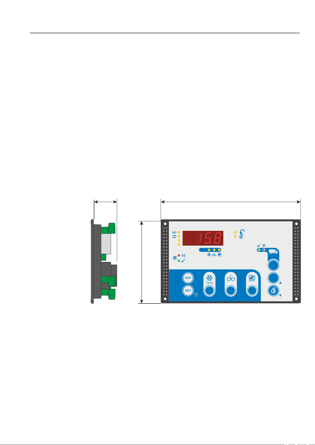
1.6 Dimensions Page 7
1.7 Technical data Page 8
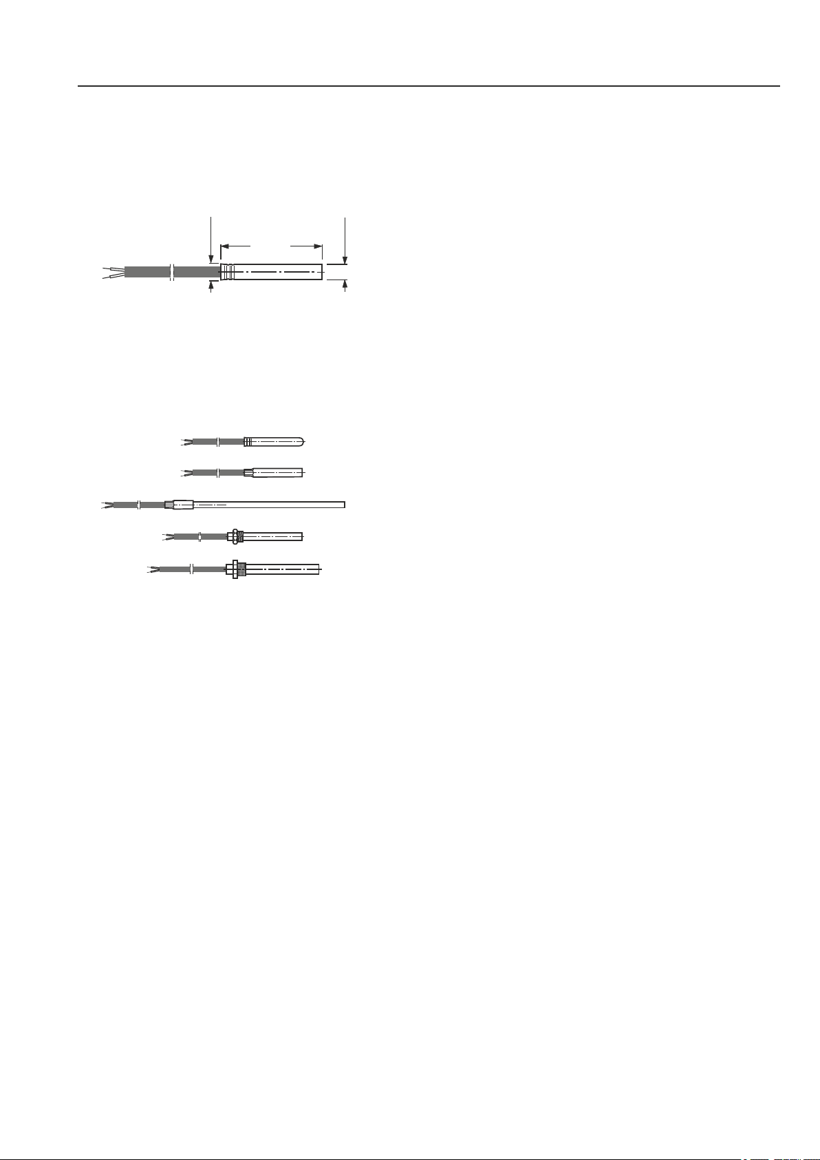
1.8 Sensor dimensions and technical data sensor Page 9
2 Safety
2.1 General Information Page 10
2.2 Intended use Page 12
2.3 Wiring, screening, earthing Page 13
2.4 Electrical safety Page 13
3 Installation
3.1 Location and climatic conditions Page 14
3.2 Unpacking and storage Page 14
3.3 Installation of housing Page 14
3.4 Fitting the sensor Page 15
4 Electrical connection
4.1 Safety during installation Page 16
4.2 Procedure Page 16
4.3 Wiring Page17
4.4 Connection diagram Page 18
4.5 Wiring the digital inputs Page 19
4.6 Connection robot Page 19
4.7 Connection of external pressure sensor (optional) Page 19
5 Operation
5.1 Function overview Page 20
5.2 The configuration software KONSOFT Page 23
5.3 Guideline for the initial installation / parameterization Page 24
5.4 Setting the date and time Page 26
5.5 Operation in levels Page 27
5.6 Operation of working level Page 28
5.6.1 Button functions Page 29
5.6.2 Meaning of the LEDs Page 30
5.6.3 Operation modes Page 32
6 Cleaning
6.1 Cleaning methods (cooling tank-configurations) Page 36
6.1.1 Circulation cleaning with a beaker Page 36
6.1.2 Circulation cleaning with two dosing pumps Page 36
6.1.3 Displacement cleaning with feed container, dosing pumps
in circulation line Page 37
6.1.4 Displacement cleaning with feed container and dosing pumps Page 37
6.2 Page 38Cleaning programme diagram
6.3 Explanation and programming of the cleaning process Page 39
6.3.1 Service functions for testing the cleaning cycle Page 46
7. Tank monitor and general fault handling
7.1 Description of tank monitor operation Page 48
7.2 Tank monitor: Milk removal YES or NO Page 50
7.3 Tank monitor: Handling multiple faults Page 53
7.4 Tank monitor: Display fault memory Page 53
7.5 Listing fault codes and their description Page 54
7.5.1 Critical tank monitor alarms (red) Page 54
7.5.2 Informative tank monitor alarms (green) Page 55
7.5.3 System alarms cleaning Page 56
7.5.4 System alarms cooling Page 58
7.5.5 System alarms external sensors Page 59
7.5.6 Test alarm Page 59
8. Setting of parameters
8.1 Change and save parameter values Page 60
8.2 Level „General cooling parameters“ c-parameter Page 62
8.3 Level „Extended cooling parameters“ P-parameter Page 64
8.4 Level „General cleaning parameters“ n-parameter Page 69
8.5 Level „Extended cleaning parameters“ r-parameter Page 72
8.6 Level „Service parameters“ E-parameter Page 77
8.7 Level „General tank monitor parameters“ h-parameter Page 78
8.8 Level „Extended tank monitor parameters“ H-parameter Page 80
8.9 Level „Alarm -> Event assignment“ F-parameter Page 82
8.10 Level „Hardware assignment“ A-parameter Page 84
8.11 Level „I-/O- test parameters“ o-parameter Page 90
9. Other information
9.1 Butterfly valve (manual or pneumatic) Page 92
9.2 Safety switch for manual butterfly valve Page 93
9.3 Robot control Page 94
9.3.1 Cleaning release by robot Page 95
9.4 Different variants for cooling start delay Page 96
9.5 Compressor switch-on delay / pre-agitating Page 98
9.6 Emergency cooling / sensor failure Page 98
9.7 Sensor correction procedure Page 98
9.8 Function second temperature sensor Page 99
9.9 Alarm level during cooling Page 98
9.10 Automatic / convenience functions Page 98
9.10.1 Autom. start to cont. agitating mode after exiting cooling mode Page 98
9.10.2 Automatic start to cooling mode after successful cleaning Page 98
9.11 Heating control Page 100
9.12 Function of pressure switch – Effect on pump and heater Page 100
9.13 Air in the cleaning pump -> automatic venting Page 101
9.14 Level control setting Page 102
9.15 Detergent injection position Page 103
9.16 Configuration of the different stages Page 103
9.17 Setting of a break in the cleaning programme Page 104
9.18 Page 104Function test alarm
9.19 Activation delay tank monitor Page 105
. Procedure following power failure9 20 Page 106
9.21 Power pack (optional) Page 106
9.22 Agitator monitoring module (optional) Page 107
9.23 Connection /Param. external analogue pressure sensor Page 108
9.24 Tank overflow protection Page 108
9.25 Tanks with various cooling levels Page 109
9.26 Anti-freezing protection by means of low pressure monitoring Page 109
9.27 General measures when using electronic control systems Page 110
Circuit diagram
is stored in the control box
105204 WTS-300 V2.0 - 11.01.2019 105204 WTS-300 V2.0 - 11.01.2019