Weldmax KWM295SWF User manual

WELDMAX - 1 - MIG S (3-phase) + SWF 2
M I G / M A G P o w e r S o u r c e w t h s e p a r a t e W r e F e e d e r

WELDMAX - 2 - MIG S (3-phase) + SWF 2
M I G / M A G P o w e r S o u r c e w t h s e p a r a t e W r e F e e d e r

WELDMAX - 3 - MIG S (3-phase) + SWF 2
M I G / M A G P o w e r S o u r c e w t h s e p a r a t e W r e F e e d e r

WELDMAX - 4 - MIG S (3-phase) + SWF 2
Content
1. Introduct on.............................................................................................................................................5
2. Spec f cat on............................................................................................................................................5
3. Transport and storage..............................................................................................................................5
4. Installat on...............................................................................................................................................6
5. Operat on.................................................................................................................................................6
6. Trouble shoot ng.....................................................................................................................................7
7. Ma ntenance............................................................................................................................................8
8. Parts l st...................................................................................................................................................8
9. C rcu t d agram......................................................................................................................................10
M I G / M A G P o w e r S o u r c e w t h s e p a r a t e W r e F e e d e r

WELDMAX - 5 - MIG S (3-phase) + SWF 2
1. Introduction
In case of MIG/MAG weld ng method the arc s generated between the automat cally fed welding wire and the
working piece, sh eld ng n CO2 gas or gas m xture.
The mach ne s able to weld unalloyed and low alloyed steel plates. When weld ng th n car chass s, the
appl cat on of gas mixture s recommended, wh lst n other cases, when deep penetrat on s requ red, pure CO2
renders better solut on.
Important advantages of th s technology are h gh heat concentration and current density so warp of the
mater al s very low.
Add t onal advantages:
♦ h gh weld ng speed, qu ck melt ng, ♦ w de range of weld ng parameters,
♦ deep penetrat on, h gh melt ng rate, ♦ easy automat on,
♦ ab l ty to weld of th n plates, roots, etc., ♦ no slag on the welded seam.
The equ pment cons sts of two, separated un ts: the Power Source and the Wire Feeder, and they are
connected w th cables and hoses of 10 m long. The power source s des gned to const tute a compact un t w th
the gas bottle and the undercarriage f xed to t.
Ma n parts of these un ts:
♦ Metal hous ng w th wheels and fan ♦ Metal hous ng w th central torch adaptor
♦ Ma n transformer (of flat stat c character st c) ♦ W re feed ng un t w th motor
♦ Rect f er br dge ♦ Soleno d (gas) valve
♦ Choke for smooth ng the current ♦ Electron c control un t
♦ Aux l ary transformer and contactor ♦ Connect ng cables and hoses (10 m)
2. Specification
Power Source Wire Feeder
Ma ns voltage 3×415 V, 50 Hz Input voltage 42 V, 50 Hz
Nom nal nput power 16 kVA Max mum nput power 75 VA
Max mum nput current 3×22 A Max mum nput current 2 A
Input fuse 3×T25 A
Open c rcu t voltage (DC) 18 - 45 V W re d ameter 0.8-0.9 / 1.0-1.2 mm
Weld ng current range 40 A/16 V - 380 A/33 V Max. weld ng current 500 A
Duty cycle 70% - 355 A, 100% - 300 A Duty cycle 100%
Number of weld ng steps 30 (3×10) W re feed speed 0 - 18 m/m n
Cool ng AF Cool ng AN
Insulat on class I Shock prevent on class III
We ght (approx.) 130 kg We ght (approx.) 22 kg
D mens ons (w×h×l)
w thout wheels
440 × 830 × 985 mm
440 × 660 × 985 mm
D mens ons (w×h×l)
w thout wheels
350 × 520 × 590 mm
230 × 430 × 590 mm
Class of heat res stance: F; Protect on class: IP 21.
3. Transport and storage
The manufacturer del vers the equ pment w th standard accessories and undercarriage mounted. Before
transport, the mach ne has to be secured aga nst t pp ng over and protected aga nst adverse effects of the weather.
It must be stored at dry, covered places.
It shall be loaded and unloaded by lift trucks.
Protect t aga nst mo sture and mechan cal shock carefully!
M I G / M A G P o w e r S o u r c e w t h s e p a r a t e W r e F e e d e r

WELDMAX - 6 - MIG S (3-phase) + SWF 2
4. Installation
The equ pment must be operated at places prov d ng all the necessary cond t ons for ts safe operation.
The mach ne should be connected to a l ne prov ded w th protect ve grounding, fuse and d fferent al protect on
sw tch.
Always comply w th the provisions of standards when repa r ng and nstall ng the equ pment.
♦ Equ p the gas bottle w th pressure regulator and flow meter accord ng to
the nstruct on manuals. Put the gas bottle onto the power source, secure t by
the cha n carefully and mount the flare nut of the gas hose to the regulator output
by a wrench.
Leakage should be checked at both ends e.g. by soap-water.
♦ Open the cover of the wire feeder. The reel holder s placed n a room
separated from the electr c parts.
Push the wire reel onto the holder. Make free the end of the w re and cut t
smoothly. The reel's braking can be adjusted by the bolt located on the m ddle of the
holder, after remov ng the nut wh ch f xes the reel.
♦ The wire feeding echanis wh ch s mounted electr cally
solated from the body serves for the reliable feed of the weld ng
w re. The shaft of the feed ng motor s equ pped w th a drive (or
feeding) roll, the groove of wh ch al gns the weld ng w re.
The w re s pressed aga nst the dr ve roll by a free runn ng
bearing roll pressed down by the pressure arm. The pressure on
the dr v ng roll can be adjusted by a screw. The w re s gu ded by
a guiding spiral.
The feed ng roll marked at ts outer surface has two grooves. In
case of chang ng the w re, remove shaft nut and turn the feed ng
roll.
Unlock the pressure arm and al gn the w re nto the groove of
the dr ve roll putt ng a short part of the w re nto the central
adaptor. F nally, put the cover back, to protect the w re reel and
the feed ng un t aga nst contam nat on.
♦ Connect the...
•wire feeder to the power source by weld ng and
control cable and gas hose (accessor es, n a 10 m
long protect ve hose);
•torch to the standard central adaptor;
•earth cable to a socket on the power source's front
plate (accord ng to the less spatter);
•earth clamp to the work p ece or bench.
The gas hose (to the cyl nder), and the mains cable are
located at the power source's rear plate.
5. Operation
•Q1: Ma n and coarse sett ng sw tch
•Q2: F ne sett ng sw tch
•H1: 'Power on' lamp
•F1,F2: Fuses (aux l ary transformer, 1A)
•F3: Fuse (fan motor, 1A)
•F4: Fuse (w re feeder, 3.15A)
•C.A.: Central adaptor
•V-A: Volt-Ampere-meter (option)
Thermo-switches wound onto the ma n transformer prevent the power source from overheat ng, n th s case the
weld ng voltage and w re feed ng are switched off. The yellow LED on the wire feeder s gnals th s. After the
bu lt- n fan cools the equ pment down (through the vent-holes by a r flow), weld ng can be cont nued.
M I G / M A G P o w e r S o u r c e w t h s e p a r a t e W r e F e e d e r
Gu d ng
sp ral
Pressure screw
Bear ng
roll
Roll pres-
sure arm
Dr ve (feed-
ng) roll
V-AF1-F4
Q2
Q1
H1
0 m
(to back)
Earth Cable
C. A.
Electron c
un t
WELD
SWF2
o
Type :
Inp ut vo lta ge
Ma x. p owe r inp ut
Re mo te -c on tr o l
Du ty cy cle
Wi re si ze
0.8 - .2
00%
7 5VA
IP2
Pr ot e cti o n
Ins ulat ion c lass
Ma chin e N-
F
WELDMAX SWF2/395
Technical Data
Made in Hungary
1
2
3
4
56
7
9
8
10
PRO G R A MM E
S
S
0, 5
1, 5
2,5 se c. 0, 5
1, 5
2, 5 se c.
WELD
1
3
2
4
6
7
8
9
10
5
01
2
3
3
X
0
1
1
U
S
S
AF
F
2
I
( )
A
2
2
U
U
( )
( )
V
V
2
I
( )
A
2
I
( )
A
[ ]
V
40A / 16 V - 380A / 33V
60%
355
31.5
100%
300
29
50Hz
T25A
IP21 EMC:2 A
Cla in .
Coolin g
3 EN 60974-1
Type:
WELDMAX 395 S
18-4 5
co =0.7
j
22 15
16 11
Technical Data
Made n Hungary
Coarse settings Fine settings
WELD
395S
mig

WELDMAX - 7 - MIG S (3-phase) + SWF 2
The mach ne s controlled by an electronic unit wh ch prov des the
feed ng motor's DC voltage, sw tches the contactor and gas valve on/off
and controls the weld ng process.
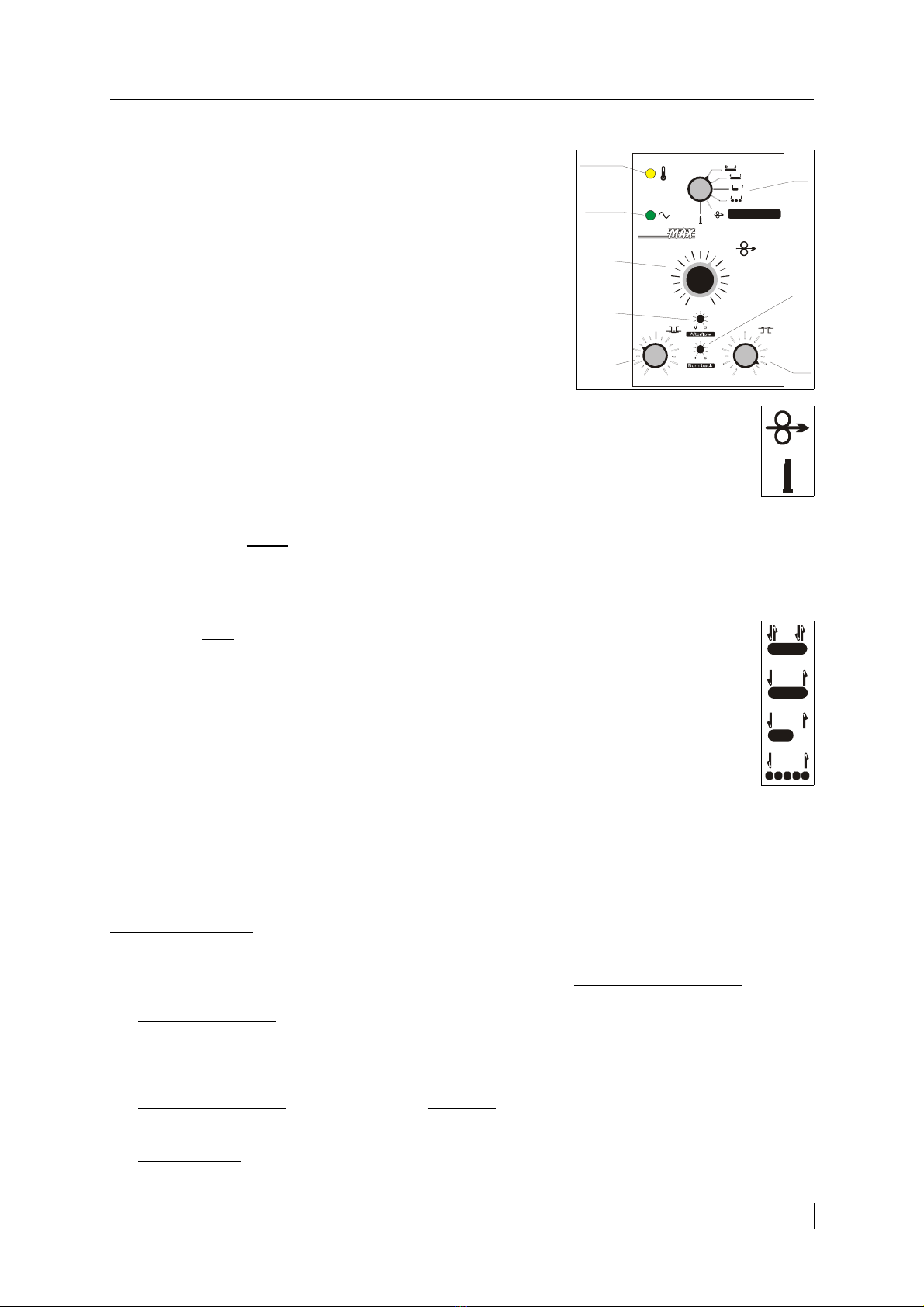
•Green LED: s gnals the mach ne's on.
•Yellow LED: s gnals the overheat ng of the power source.
•K: Funct on selector sw tch.
•P4: W re feed speed potent ometer.
•P7: Weld ng on t me potent ometer.
•P8: Weld ng off t me potent ometer.
•P1: W re burn back (m n ) potent ometer.
•P2: Gas post-flow t me (m n ) potent ometer.
Two operat on modes wh ch can be chosen by the sw tch K are:
Wire threading: Wh le pushing the torch button, the feeder s feeding
the w re w th speed approx. 10 m/m n. nto the torch cable (any other funct ons are proh b ted). For
smooth w re feed, keep torch cable as straight as poss ble dur ng th s operat on. In case of slippage
of the w re, ncrease dr ve roll pressure by the set screw.
Gas test: Wh le pushing the torch button, the gas valve s open (any other funct ons are
proh b ted). Dur ng th s t me the quant ty and the pressure of gas can be checked and set. Set gas
flow between approx. 16-20 l/m n (depending on the weld ng current).
The weld ng can be started by push ng the button on the weld ng torch:
•F rst there s only gas pre-flow ( ts durat on can be 0-0.5 sec., sett ng by P3 potent ometer on the PCB);
•Afterwards the wire feeding beg ns, w th soft start ( ts durat on s set to 0.2 sec. by P9 on PCB), and also the
welding current starts.
The weld ng work s accord ng to the operat on modes set by the funct on selector sw tch (K):
4-stroke mode: Releas ng the button the weld ng continues and t stops only f the button s pushed
aga n.
2-stroke mode: After releas ng the button, the weld ng stops.
Spot welding: After the set t me s f n shed (or releas ng the button), the weld ng stops. The
durat on of the spot weld ng can be set by P7 potent ometer (0.5-2.5 sec).
Interval welding: The weld ng stops f the button s released n the pause t me. The durat on of the
feeding can be set by P7, wh le the pause t me can be set by P8.
When the weld ng s f n shed:
•F rst the wire feeding stops ( f t works);
•Elaps ng the w re burn back t me (P1), the welding current ceases;
•Elaps ng the gas post-flow t me (P2), the gas flow stops, too.
The P6 potent ometer on the PCB sets the m n mal w re speed, wh le the P5 sets the max mal one.
6. Trouble shooting
All repa r works are needed to be carr ed out by a technician, on disconnected mach ne!
If the fault of the equ pment rema ns or s caused by an unknown reason, contact the serv ce d v s on!
•The green LED s off: Faulty sw tch (Q1), ma ns cable or transformer(s); ⇒ replace t or contact the serv ce.
Bad electr c connect ons to the power source; ⇒ check these cables.
•Blown fuse: ⇒ F nd the cause of trouble (short c rcu t may be ns de!), replace fuse and check ts rat ng.
•The yellow LED s on: The power source s overheated; ⇒ wait unt l the fan cools t down and the LED
ext ngu shes.
•No weld ng arc: Faulty torch or ts cable or button; ⇒ replace t. Loose connect on at weld ng cables; ⇒
fasten t. Faulty control un t; ⇒ contact serv ce.
M I G / M A G P o w e r S o u r c e w t h s e p a r a t e W r e F e e d e r
Green
LED
Yellow
LED K
P7
P1
P2
P8
P4
1
2
3
4
5 6
7
9
8
10
PROGRAMME
S
S
0,5
1,5
2,5 sec. 0,5
1,5
2,5 sec.
WELD

WELDMAX - 8 - MIG S (3-phase) + SWF 2
•Bad gas flow: Empty gas bottle, faulty pressure regulator or flow meter, leakage at gas hose or gas valve; ⇒
repa r or replace. The bottle or regulator s frozen, ⇒ heat up t by hot water or gas heater.
•Irregular w re feed: Worn or deformed nput gu de, roll or ts groove, loose w re reel; ⇒ locate fault and
repa r t. Bad pressure on the roll; ⇒ set correct pressure. Faulty control un t; ⇒ contact serv ce.
•Bad qual ty of weld: Bad gas flow, ncorrect w re speed, contam nated surface, mproper qual ty of w re or
gas, bad weld ng parameters, worn parts of mach ne ⇒ use good quality products for weld ng, maintain the
mach ne regularly.
It s very mportant that the weld ng parameters would be set properly for the weld ng task:
→ Welding current: can be regulated by the w re feed speed, v a the melt ng output.
→ Arc voltage: weld w th a short arc f t s poss ble; w dth, depth and surface of the seam depend also on th s.
→ Sticking out: t s recommended to be short; t nfluences the melt ng output, gas sh eld ng, spatter loss.
→ Polarity: the reverse polar ty can be used only for p l ng weld ng.
→ Nozzle-to-work distance: be short because of gas sh eld ng, but the gas nozzle must be protected from heat.
→ Leading of the torch: usually pulling; the pushing weld ng can be used for root welding because of the w de
and flat seam.
7. Maintenance
Ma ntenance and repa r works can be carr ed out by a tra ned personnel only on equ pment disconnected from
the ma ns. Don't touch the ns de electr c parts under voltage!
The electr c shock prevention tests must be carr ed out regularly as prescr bed.
•Torch: Dur ng the weld ng work apply ant -
adhes ve flu d (s l con spray) to the gas nozzle to
prevent melted droplets adher ng to t. The
contact tip s a consumable part to be changed
regularly depend ng on ts wear (burn ng,
eros on). The torch liner should only be cleaned
by gasol ne-o l m xture and blown out w th
compressed a r.
•Cables and hoses: Check gas hose and input/output cables for flaws, replace f necessary.
•Wire feeder: Th s must be checked and ma nta ned regularly at the drive roll and the guiding spiral.
•High-current unit: Remove dust from ns de the equ pment us ng compressed a r. Check and - f necessary -
tighten screw at connect ons.
8. Parts list
Accessories:
NoPart Code NoPart Code
1. Feed ng roll Ø40/22, Ø0.8-1.0 "V" 2342240646 2. Earth cable 50 mm2, 10 m 2343630016
3. Output plug CX-22 (on earth cable) 2142240692 4. Earth clamp 2142240184
5. Gas hose Ø9/5, 10 m 2357320078 6. 1/4" flare nut (on gas hose's end) 900-000-002
7. Protect ve hose 10 cm×10 m 2167320021 8. Weld ng cable 50 mm2, 10 m 2343630053
9. Output plug CX-22 (to the PS) 2142240692 10. Output plug CX-42 (to the WF) 2142240617
11. Control cable 5×1.0 mm2, 10 m 2343630071 12. 6+1-p n plug T3104 (to the PS) 2143730091
13. 6+1-p n plug T3105 (to the WF) 2143730089
M I G / M A G P o w e r S o u r c e w t h s e p a r a t e W r e F e e d e r
Tube
Gas nozzle Push-button
Handle
Contact t p

WELDMAX - 9 - MIG S (3-phase) + SWF 2
Power Source:
NoPart qty Code NoPart qty Code
1. Plast c handle 2 2142240014 2. Fan holder Ø300 1 28422411
3. Fan blade Ø300 1 2142240178 4. Cap for lamp 18×18, green H 1 2342340065
5. Cable f x ng clamp (mains cable) 1 2342240567 6. Gas hose Ø9/5 (to the gas bottle) 1 2357320008
7. 1/4" gas connector (to Wire F.) 1 900000-001 8. 3/8" flare nut (on gas hose's end) 1 900000-117
9. Ma ns cable 4×2.5 mm2, 5 m 1 2343630024 10. Fuse holder G-30 (500V) F ,F2 2 2343730050
11. Fuse B30/6.3, 1A F ,F2 4 2343730052 12. Fuse holder PTF-35 F3,F4 2 2343730015
13. Fuse B20/5.2, 1A (fan) F3 2 2343730016 14. Screw term nal K2.5B 1 2343730009
15. Contactor LC1 D32-01, 42V K 1 2142320096 16. F lter un t EMC-3 1 28040623
17. Fan motor VNT 34-45, 230V M 1 2142241120 18. Sw tch GN 25-6720 (0–3) Q 1 2142330065
19. Sw tch GN 25-8407 ( – 0) Q2 1 2142330160 20. Aux l ary transformer T2 1 29081140
21. Ma n transformer T 1 29080495 22. Rect f er br dge PTS 390 V 1 2142240233
23. DC choke L 1 29090296 24. Output socket CX-31 3 2142240068
25. Fuse B20/5.2, 3.15A (feeder) F4 2 2343730049 26. Lamp holder 18×18, LJ 243 H 1 2342340064
27. Bulb T4.5, 48V 1 2345210001 28. 6+1-p n socket T3107 X2- 1 2143730087
Opt on: Shunt 600A/60 mV (S , 28475413) and V-A-meter (2147540008).
Wire Feeder:
NoPart qty Code NoPart qty Code
1. Plast c handle (half) 4 2142240230 2. Sw vel wheel Ø65 4 2132750047
3. Sw vel plate 1 2142240110 4. W re reel holder 1 2142240076
5. Feed ng mechan sm 2465L-502D 1 2142241561 6. Feed ng roll Ø40/22, Ø0.9-1.2V 1 2342240737
7. Standard central adaptor 1 2142240095 8. Output socket CX-12 1 2142240155
9. 6+1-p n socket T3106 X2-2 1 2143730088 10. Aux l ary transformer T 1 29081120
11. Soleno d valve 42V~ Y 1 2142241101 12. Feed ng motor 24VDC 65W M 1 2142241561
13. Electron c un t MHT 3.0 A 1 2142241056 14. 11-p n PCB connector 1 2342240179
15. Turn ng knob FF-25 (P4) 1 2342240017 16. Turn ng knob FF-16 (K,P7,P8) 3 2342240015
M I G / M A G P o w e r S o u r c e w t h s e p a r a t e W r e F e e d e r

WELDMAX - 10 - MIG S (3-phase) + SWF 2
9. Circuit diagra
M I G / M A G P o w e r S o u r c e w t h s e p a r a t e W r e F e e d e r
Table of contents
Other Weldmax Welding System manuals
Popular Welding System manuals by other brands

Deca
Deca Domus 171E instruction manual

Miller Electric
Miller Electric SCP-200C owner's manual

WeldCorp
WeldCorp INVERTER 80 Owner's operating manual

bester
bester PDE 50 Operator's manual

Campbell Hausfeld
Campbell Hausfeld WF2010 Operating instructions & parts manual

Miller
Miller Shielded Metal Arc Welding Guidelines