manuals.online logo
Brands
  1. Home
  2. •
  3. Brands
  4. •
  5. Weldmax
  6. •
  7. Welding System
  8. •
  9. Weldmax WEM221ACDC User manual

Weldmax WEM221ACDC User manual

Operators Manual
WEM221ACDC
221 AC/DC
Ultima modifica/Last Update/Letzte Veraenderung: 23/04/2014 Rev1 pagina 13 di 35
CAUTION!
Before carrying out any work on the machine
make sure it is off and the plug has been dis-
connected.
!
The machine does not
switch on.
 Lack of power supply
 Voltage reaches the machine switch but
there is no voltage after the contacts.
 There is voltage after the disconnecting
switch but the machine does not go on.
 Make sure the line switch is closed, the
protection devices (fuses) are not enabled
and that the power supply cable is in good
condition.
 Switch the machine off and disconnect the
plug. Make sure that when the switch is
closed, there is continuity between the
contact input and output and the varistor is
not broken. If broken, replace board 0074.
(Picture 1).
 Switch the machine off and disconnect the
plug. Check the PFC Module on the power
board, if it is damaged, replace the power
board (Picture 2)
The protection devices
of the line set off when
the switch is activated
and the machine does
not go on.
 Damaged power supply cable with short-
circuited wires.
 Inverter is damaged.
 Switch off the machine and disconnect the
plug. Make sure that there are no short
circuits between the poles of the plug
caused by a damaged power supply cable.
 Switch off the machine and disconnect the
plug, then check :
- varistor (Picture 1);
if it is damaged, replace the power board
0074;
 Inverter (Picture 4) or
 PFC Module (Picture 2),
if they are damaged, replace the power
board 0070;
 Input bridge rectifier (Picture 3);
if it is damaged, verify also inverter and
PFC module.
If they are working then replace only the
Input rectifier, otherwise both.
The front panel does
not switch on.
 The fan works but the front panel does
not go on.
 Switch off the machine and disconnect the
plug. Make sure the flat cable that con-
nects the front panel to the power board is
inserted correctly. If correctly inserted, re-
place the front panel, 050.0001.0015.
 If the front panel does not go on, check
PFC Module. If it is damaged, replace the
power board (Picture 1)
221 AC/DC
Ultima modifica/Last Update/Letzte Veraenderung: 23/04/2014 Rev1 pagina 14 di 35
PROBLEM CASE SOLUTION
The Machine works and  The cable that connects the Power
weld but the fan doesn’t
work (too short thermal
cycle).
Board ( 0070) to the Fan is not correctly
inserted or damaged. (Picture 6)
 The fan is damaged
 Fan speed doesn’t increase/decrease
 Connect the cable or eventually replace it
(Picture 6)
 Replace it and if it is still not working, re-
place the Power Board.
 Replace Power Board 0070
The output voltage in
MMA/TIG is about 11V
and the
Machine doesn’t weld.
 The wires that connect the output filter
board 0075 to the front panel (0015) are
not correctly connected or damaged.
 The cable that connects the inversion
board 0071 to the module board 0047 is
not correctly connected or is damaged.
 Front panel 0015 cable connected to the
Inversion Board 0071 could be discon-
nected
 Front panel board 0015 and/or
 Power board 0070 and/or
 Inversion board 0071
are damaged.
 Switch off the machine and disconnect the
plug:
 Connect the cables 0075 or if they are
damaged replace them (picture 7).
 Connect board 71 cable to board 0047,
if damaged replace it.
 Connect board 15 cable to board 0071,
if damaged replace it.
 Replace damaged Board.
 Replace damaged Board
Yellow led on.
Output voltage in each procedure is
about 11V. Thermal protection device
enabled.
 Yellow led on
 Thermal protection device keeps on
Using a continuity tester verify if::
 Protectors are open
 Protectors are closed
 None of the above mentioned cases
 Leave the machine on for few minutes to
allow the cooling of the inverter.
Switch the machine off and disconnect the
plug. Remove the hood and make sure:
 the temperature of the heat sink tool is less
than 40°C;
 If it is less than 40°C, check if the thermal
protection connectors are closed.
 They are defective, replace them
 Check that the wires are properly con-
nected to the weld lead connectors
(Picture 5).
 Erratic feeding in the power board 0070,
replace it.
221 AC/DC
Ultima modifica/Last Update/Letzte Veraenderung: 23/04/2014 Rev1 pagina 15 di 35
PROBLEM CASE SOLUTION
When welding the pro- Make sure the welding current does not Decrease the welding current.
tection devices of the
line set off.
require greater power than the one supplied
by the line.
The remote control is
damaged.
 Check that the 4-pin connector ( picture
11) is correctly inserted on the power
board 0070.
 The Front Panel could be damaged.
Insert the wires into the connectors correctly
and insert the connectors into their housings.
Should this not be sufficient, replace the front
panel board 0015
The machine does not
strike in HF mode.
 The front panel 0015 could be damaged.
 The HF board 0027 could be damaged.
 Board 0027 wiring connected to board
0015 are disconnected or damaged
 HF coil could be damaged or not con-
nected to HF 0027.
 Replace front panel board 0015.
 Replace board HF 0027.
 Connect board cables and if damaged
replace them.
 Connect HF coil to the primary circuit using
the 2 wires or replace it.
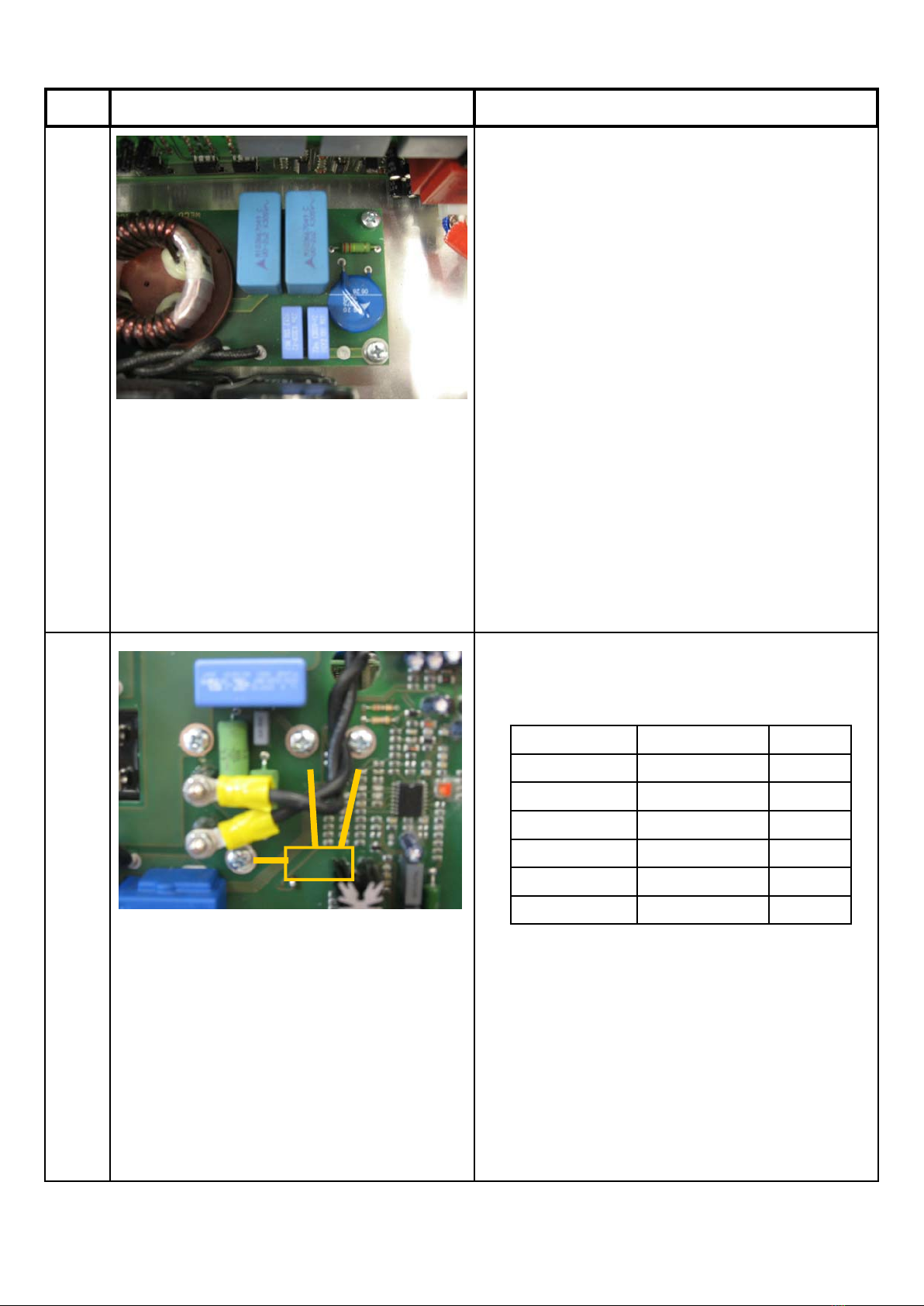
Gas does not come out  Excessive gas pressure.
from solenoid valve.
 Damage solenoid valve wiring.
 The solenoid valve control relay on the
front panel is damaged.
 No 24 V.
 Solenoid valve is damaged.
 Remove the gas connection. Carry out a
gas test on the front panel in the TIG pro-
cedure and check opening of the solenoid
valve. Reduce gas pressure. Restore con-
nections and carry out a gas test.
 Switch off the machine and disconnect the
plug:
 Should there be no continuity, single out
the disconnection and repair it;
 Make sure that the wiring contacts are
correctly inserted in the connectors.
 The Front Panel must be replaced.
 Check continuity between points A/B of the
power board and x/y poles of the connec-
tor that goes to the front panel (picture 10).
After that the solenoid valve or the front
panel must be replaced.
 Should the operations carried out not have
a positive outcome, replace the solenoid
valve.
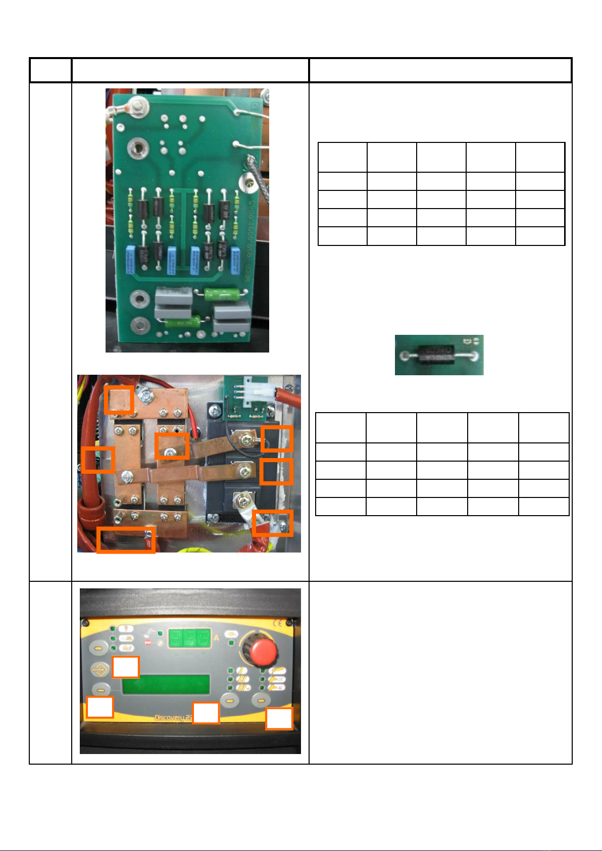
The torch button does-
n’t work.
 There is no continuity in the wiring of
amphenol board 0076.
 Torch wiring connecting boards 0076
and 0075 is broken or disconnected.
 Torch wiring connecting boards 0075
and 0015 is broken or disconnected.
 24V wiring connecting power board and
front panel board is damaged or discon-
nected.
 Front panel board 0015 is damaged.
 Check if the wiring is connected, if con-
nected test the continuity.
 Replace wiring
 Replace wiring
 Replace wiring
 Replace wiring
221 AC/DC
Ultima modifica/Last Update/Letzte Veraenderung: 23/04/2014 Rev1 pagina 16 di 35
PROBLEM CASE SOLUTION
The machine always
welds at maximum cur-
rent.
 The Front Panel 0015 is damaged.
 The Power Board 0070 is damaged.
 The Hall Effect is damaged or the cable
is disconnected.
Switch off the machine and disconnect the
plug:
 The Front Panel 0015 must be replaced.
 The Power Board 0070 must be replaced.
 Connect the cable in the right way, or if
damaged, the Hall Effect must be re-
placed.
Gas comes out but the Pre-gas settings are not correct.
machine doesn’t weld.
Regulate pre-gas settings.
The machine can’t stop
welding or the welding
current is not the one
set.
The slope up and slope down are not cor-
rectly set.
 Regulate in the correct way the slopes.
 Otherwise, reset the parameters and reset
the machine (Picture 9).
The output voltage in
MMA/TIG is zero and
the welding procedure
is blocked in MMA.
 ISOTOP diodes are in short circuit.
 The Inversion Module is damaged..
 Board 0065 transils damaged
 TF POT inductive value is null
Turn off the machine and remove PCB 0065
(sopra diodi ISOTOP) (figura 8):
 Replace them
 Replace Module and Board 0071;
 Replace Board 0065;
 Replace TF POT if damaged.
Poor welding quality  Spattering occurs during MMA welding.  Make sure welding polarity is correct, the
 The arc switches off while welding AC
earth clamp is fixed correctly and check
the hot-start and arc-force values that have
to be decreased if they are too high.
 The inversion board 0071 or the front
panel 0015 must be replaced.
221 AC/DC
Ultima modifica/Last Update/Letzte Veraenderung: 23/04/2014 Rev1 pagina 17 di 35
SPIEGAZIONE
The varistor is a blue discs near the ground wire of the
power board. This device is for protecting the board from
input overvoltage. When there is overvoltage they
“explode” causing a short circuit most of the times. If the
extent of the short circuit is very high they become an
open circuit.
To check the PFC of the switching power supply unit,
carry the following measurements with a diode tester:
Should there be a short-circuit on one of these measure-
ments or an “OL” instead of a numeric value, the power
board must be replaced.
PICTURE 1
Red Probe Black Probe Measure
D S “OL”
S D 380
G S 1.69
S G “OL”
G D 1.69
D G “OL”
PICTURE 2
D S G
221 AC/DC
Ultima modifica/Last Update/Letzte Veraenderung: 23/04/2014 Rev1 pagina 18 di 35
EXPLANATION
Input bridge rectifier .
To check the Input bridge rectifier , carry out the following
measurements with a diode tester:
Should there be a short circuit on one of these measure-
ments, the input bridge rectifier must be replaced.
To check the inverter, carry out the following measure-
ments with a diode tester:
Should there be a short-circuit on one of these measure-
ments or an “OL” instead of a numeric value, the power
board must be replaced.
Make sure the two terminals of the thermal devices are
well inserted in the 8-pin white connector on the power
board 0070.
Rheofore Probe Rheofore Probe Measure
F+ Red D Black “OL”
F− Red D Black 0.5
F+ Black D Red 0.5
F− Bleck D Red “OL”
PICTURE 3
PICTURE 4
Red Probe Black Probe Measure
S G >2.00
G S >2.00
PICTURE 5
IMPUT RECTIFIER
D F-
F+ D
G
G
G
G
S
S
S
221 AC/DC
Ultima modifica/Last Update/Letzte Veraenderung: 23/04/2014 Rev1 pagina 19 di 35
EXPLANATION
Make sure that the fan cables +24 V are correctly in-
serted:
 2-pin connector on the power board;
 2-pin connector on the fan.
Make sure that the output filter board 0074 cables are
correctly inserted in the front panel connectors (board
0015).
PICTURE 6PICTURE 7
221 AC/DC
Ultima modifica/Last Update/Letzte Veraenderung: 23/04/2014 Rev1 pagina 20 di 35
EXPLANATION
To check diodes remove the snubber board and carry out
the following measures with a diode tester:
At the ends of the two transils (see below) positioned on
the snubber board, “OL” must always be measured.
Press S3 and S5 while switching on the machine until
appears RECALL FACTORY SETUP.
After that confirm the parameter resets by pressing the S2
button.
Copper
bar
Probe Copper
bar
Probe Measure
SX red UP/DOWN black 0.3
SX black UP/DOWN red “OL”
DX red UP/DOWN black “OL”
DX black UP/DOWN red 0.3
PICTURE 8
PICTURE 9
Copper
bar
Probe Copper
bar
Probe Measure
SX red OUT black 0.3
SX black OUT red “OL”
DX red OUT black “OL”
DX black OUT red 0.3
S2
S3 S4 S5
UP
DX DX
DOWN
SX SX
OUT
221 AC/DC
Ultima modifica/Last Update/Letzte Veraenderung: 23/04/2014 Rev1 pagina 21 di 35
EXPLANATION
Check continuity, with a diode tester, between points A/B
of the power board and x/y poles of the connector that
goes to the front panel.
PICTURE 10
X
y
A
B
221 AC/DC
Ultima modifica/Last Update/Letzte Veraenderung: 23/04/2014 Rev1 pagina 22 di 35
EXPLANATION
4 pin connector 24V
PICTURE 11
221 AC/DC
Ultima modifica/Last Update/Letzte Veraenderung: 23/04/2014 Rev1 pagina 35 di 35

Other Weldmax Welding System manuals

Weldmax KWM295SWF User manual

Weldmax

Weldmax KWM295SWF User manual

Weldmax Pulse Technik Series User manual

Weldmax

Weldmax Pulse Technik Series User manual

Popular Welding System manuals by other brands

Telwin TECNICA 190 TIG-MMA DC LIFT VRD manual

Telwin

Telwin TECNICA 190 TIG-MMA DC LIFT VRD manual

PROPOINT PROCUT45 user manual

PROPOINT

PROPOINT PROCUT45 user manual

Miller XR-D Control owner's manual

Miller

Miller XR-D Control owner's manual

Rtech I-MIG200 Operation instructions

Rtech

Rtech I-MIG200 Operation instructions

ESAB AristoMig 4004i Pulse instruction manual

ESAB

ESAB AristoMig 4004i Pulse instruction manual

VITO PRO POWER VIT1200 instruction manual

VITO

VITO PRO POWER VIT1200 instruction manual

Kemppi MINARC 120 operating instructions

Kemppi

Kemppi MINARC 120 operating instructions

GYS EASYMIG 110 manual

GYS

GYS EASYMIG 110 manual

Amada PU-G Operation manual

Amada

Amada PU-G Operation manual

EWM Tetrix 551 AC/DC Smart FW operating instructions

EWM

EWM Tetrix 551 AC/DC Smart FW operating instructions

Murex Tradesarc 200 instruction manual

Murex

Murex Tradesarc 200 instruction manual

Lincoln Electric IDEALARC DC-655 Operator's manual

Lincoln Electric

Lincoln Electric IDEALARC DC-655 Operator's manual

Miller Syncrowave 210 owner's manual

Miller

Miller Syncrowave 210 owner's manual

Abicor Binzel ABIPLAS 71 HF operating instructions

Abicor Binzel

Abicor Binzel ABIPLAS 71 HF operating instructions

Forney 220 AC/DC operating manual

Forney

Forney 220 AC/DC operating manual

Panasonic YD-630AT operating instructions

Panasonic

Panasonic YD-630AT operating instructions

Deca SW 28 instruction manual

Deca

Deca SW 28 instruction manual

Lincoln Electric spirit II 150 Technical manual

Lincoln Electric

Lincoln Electric spirit II 150 Technical manual

manuals.online logo
manuals.online logoBrands
  • About & Mission
  • Contact us
  • Privacy Policy
  • Terms and Conditions

Copyright 2025 Manuals.Online. All Rights Reserved.