Wells BWB-1S Operating instructions

IMPORTANT: WELLS MANUFACTURING PROPRIETARY INFORMATION.
DISSEMINATION OF THIS INFORMATION TO ANYONE OTHER THAN
WELLS AUTHORIZED SERVICE AGENTS IS STRICTLY PROHIBITED.
TECHNICAL CONTENT OF THIS MANUAL IS DESIGNED FOR
USE BY QUALIFIED PROFESSIONAL TECHNICIANS ONLY.
PRINTED IN UNITED STATES OF AMERICA
WELLS BLOOMFIELD, LLC
2 ERIK CIRCLE, P. O. Box 280 Verdi, NV 89439
www.wellsbloomfield.com
telephone: 775-689-5703
fax: 775-689-5976
p/n 502972 Rev. D ECN-13391 S211 071128 cps
SUPPLEMENTAL
SERVICE
INSTRUCTIONS
for
BELGIAN
WAFFLE
BAKERS
Model
BWB-1S
211
WELLS

This appliance is intended for use in commercial establishments
only.
This appliance is intended
to prepare food for human consumption.
No other use is
recommended or authorized by the manufacturer or its
agents.
Operators of this appliance must be familiar with the appliance use,
limitations and associated restrictions. Operating instructions must be
read and understood by all persons using or installing this appliance.
Cleanliness of this appliance is essential to good sanitation. Read and
follow all included cleaning instructions and schedules to ensure the
safety of the food product.
Disconnect this appliance from electrical power before performing any
maintenance or servicing.
DO NOT submerge this appliance in water. Do not splash or pour
water on, in or over any controls, control panel or wiring.
Never use a wire brush or metal scraper on aluminum components.
Use bristle or fiber brush to clean grids.
The technical content of this manual, including any wiring diagrams,
schematics, parts breakdown illustrations and/or adjustment
procedures, is intended for use by qualified technical personnel.
Any procedure which requires the use of tools must be performed by a
qualified technician.
This appliance is made in the USA. Unless otherwise noted, this
appliance has American sizes on all hardware.
Information in this manual reflects current production models as of
September 1, 2006. Specifications, model numbers, product numbers
and data subject to change without notice.
WARNING:
RISK OF
PERSONAL INJURY
Installation procedures must
be performed by a qualified
technician with full knowledge
of all applicable electrical and
plumbing codes. Failure can
result in personal injury and
property damage.
WARNING:
ELECTRIC
SHOCK HAZARD
All servicing requiring
access to non-insulated
electrical components must
be performed by a qualified
technician.
Only qualified technicians are
authorized to open any
access panel which requires
the use of tools. Failure to
follow this warning can result
in severe electrical shock.
CAUTION:
RISK OF
DAMAGE
DO NOT connect or
energize this appliance until
all installation instructions are
read and followed. Damage
to the appliance will result if
these instructions are not
followed.
PRECAUTIONS AND GENERAL INFORMATION
xi
211 502972 SvcManual for BWB-1S Belgian Waffle Bakers

Precautions & General Information …………………………… xi
Electrical Specifications ..……………………………………….. 1
Features & Operating Controls …………………………………. 2
Operational Tests …………………………………………...……. 3
Servicing Instructions
Cabinet …………………………………………………………. 5
Back Panel & Solid State Controls …………………………. 6
Grids ……………………………………………………………. 7
Cook Head Pivot ……………………………………………… 9
Bypass Hi-Limit Thermostat (older units) ………………….. 10
Wiring Diagram ……………………………………………..……. 11
Exploded Views & Parts Lists ………………………………….. 12
This manual contains information needed to properly service and repair Wells Belgian Waffle Bakers.
This manual applies to the following Wells Manufacturing models:
BWB-1S
For installation, operation and maintenance instructions, refer to Operation Manual p/n 45257.
GENERAL DIMENSIONS:
10-1/8” Wide x 14” Deep x 10-9/16” High
Appliance is 23” High with top grid open.
Refer to Wells General Layout Data sheet, p/n 44666 for current specifications.
TABLE OF CONTENTS
INTRODUCTION
1
SPECIFICATIONS
MODEL STYLE VOLTAGE
1ø AMPS POWER SUPPLY
CORD
BWB-1S Single
Belgian
Waffle Baker 120 VAC 7.5 A NEMA 5-15P
WATTS
900W
211 502972 SvcManual for BWB-1S Belgian Waffle Bakers

FEATURES & OPERATING CONTROLS
2
211 502972 SvcManual for BWB-1S Belgian Waffle Bakers
17
9
19
48
RIGHT SIDE VIEW INTERIOR VIEW
BACK VIEW
shown in “open” position back panel removed
28
47
8
27
48
10
39
40
20
66
18
42
43
73
41
16
75
BOTTOM GRID
wiring cover removed
ITEM DESCRIPTION COMMENTS
8 POWER CORD 115VAC NEMA 5-15P
9 DATA PLATE Lists manufacturer information, agency approvals and electrical specifications
10 MICRO SWITCH Initiates timer when head is rotated to cook position
16 TEMPERATURE PROBE Thermistor temperature sensor
17 HANDLE ASSEMBLY Used to safely raise / lower/ rotate grids
18 SUPPORT BRACKET Supports front of grids
19 HOLE PLUG Allows access to timer adjustment
20 WIRING COVER Protects wiring in grids
27 TEMPERATURE CONTROLLER In concert with thermistor, controls temperature of grids
28 INDICATOR LIGHT Glows during timed cook cycle
39 BEARING ASSEMBLY Supports back of grids; allows grids to rotate
40 PIVOT ASSEMBLY Holds grids in alignment; allows grids to rotate
41 RUBBER FEET Provide means of leveling waffle baker; provide non-slip support
42 BOTTOM GRID Cooking element; holds temperature probe (is “top” grid in cook position)
43 TOP GRID Cooking element (is “bottom” grid in cooking position)
47 BUZZER Sounds momentarily at end of cook cycle
48 TIMER Alerts operator at end of cook cycle; NOTE: audio signal only; does not turn off grids
66 POWER SWITCH Energize / de-energize waffle baker
(73) (HI-LIMIT THERMOSTAT) Eliminated on later models
75 DRIP TRAY Catches excess waffle batter; removable for easier cleaning

OPERATIONAL CHECKS
3
211 502972 SvcManual for BWB-1S Belgian Waffle Bakers
A. TEMPERATURE CHECK
1. Desired baking temperature is 390ºF ±5º (200ºC ±3º)
2. Turn power switch ON and allow waffle baker to heat for a
minimum of 30 minutes. Insert a pyrometer of known accuracy
between the closed grid plates and allow the reading to stabilize.
3. Temperature controller is located behind the back panel. Remove
the back panel to access. Turn the temperature controller dial
clockwise to increase; counter-clockwise to decrease.
NOTE: Manufacturer’s setting (390ºF) is indicated by a black dot
on the dial face.
B. ELECTRICAL TEST POINTS
C. AMPERAGE & RESISTANCE CHECKS
1. Total current may be checked with an inductive amperage tester
(Amprobe™ or similar) by encircling wire #4 connected to
temperature controller terminal #2.
2. Heating element is integral with the grid casting.
Disconnect wire #7 to #8 from temperature controller to check
resistance of both grids at once.
Resistance from # 7 to #8 is 16Ω(cold) ± 1Ω. A reading of 32Ω
indicates one defective element or a broken element jumper wire.
CAUTION:
ELECTRIC SHOCK
HAZARD
Live electric circuits may
be exposed during these
procedures. Take necessary
precautions to avoid electric
shock.
CAUTION:
BURN HAZARD
HOT SURFACES
Equipment surfaces may be hot
during these procedures. Take
necessary precautions to
avoid burns.
TOTAL AMPS: 7.5A
With waffle baker in the
pre-heat mode.
Data for one element:
450 Watts, 3.8 Amps
Resistance of one element
TP1 to TP2, is 32W ± 1W.
(element cold and wires
disconnected)
IMPORTANT:
Always unplug appliance
from electric power and
momentarily ground all three
prongs of the power cord
before attempting resistance
checks.
390ºF
CALIBRATION
POINT
TP1
TP3
TP2
TP4
ELEMENT / GRID
bottom shown - top similar
TEMPERATURE CONTROLLER
test points are terminals
TIMER MODULE
test points are terminals

OPERATIONAL CHECKS (continued)
4
211 502972 SvcManual for BWB-1S Belgian Waffle Bakers
D. VOLTAGE CHECKS
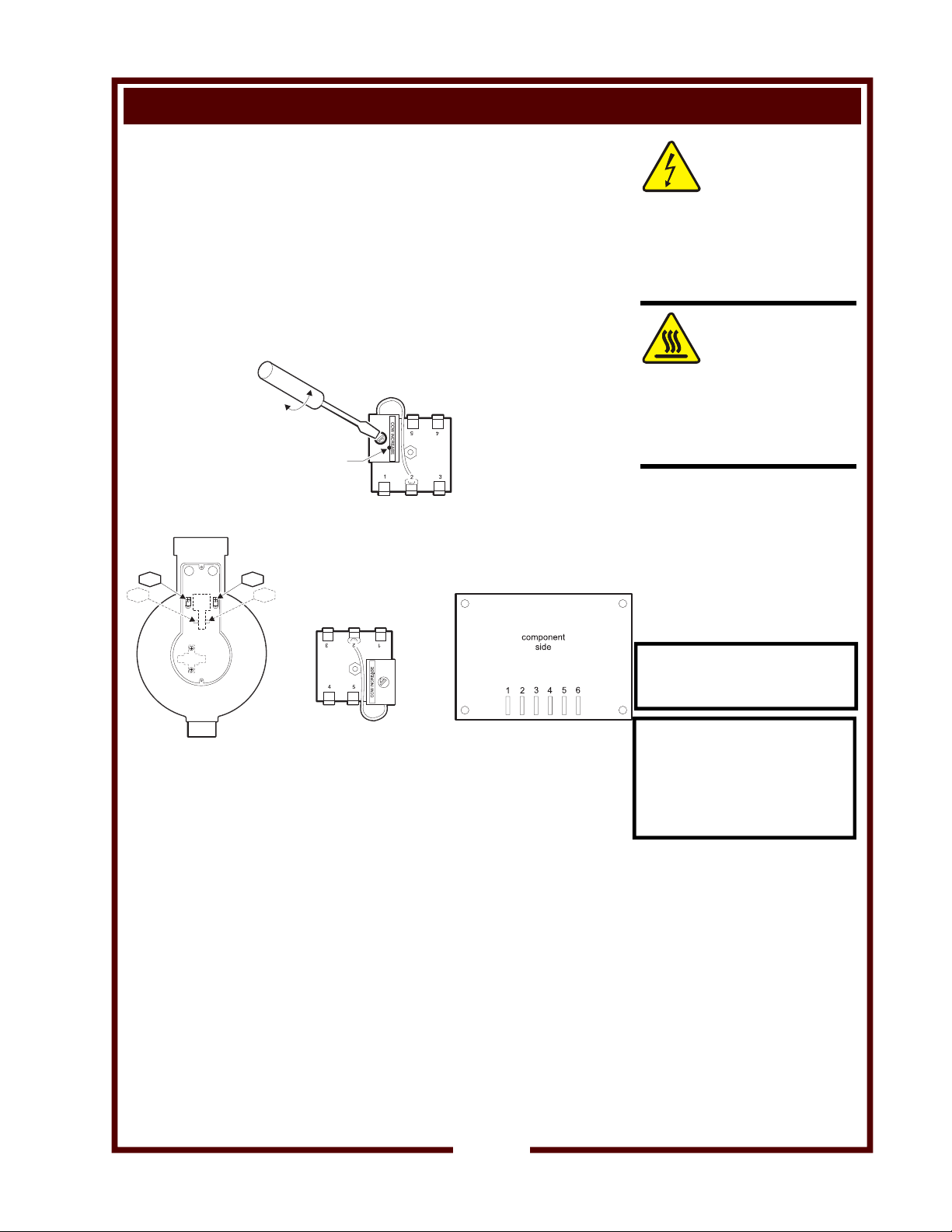
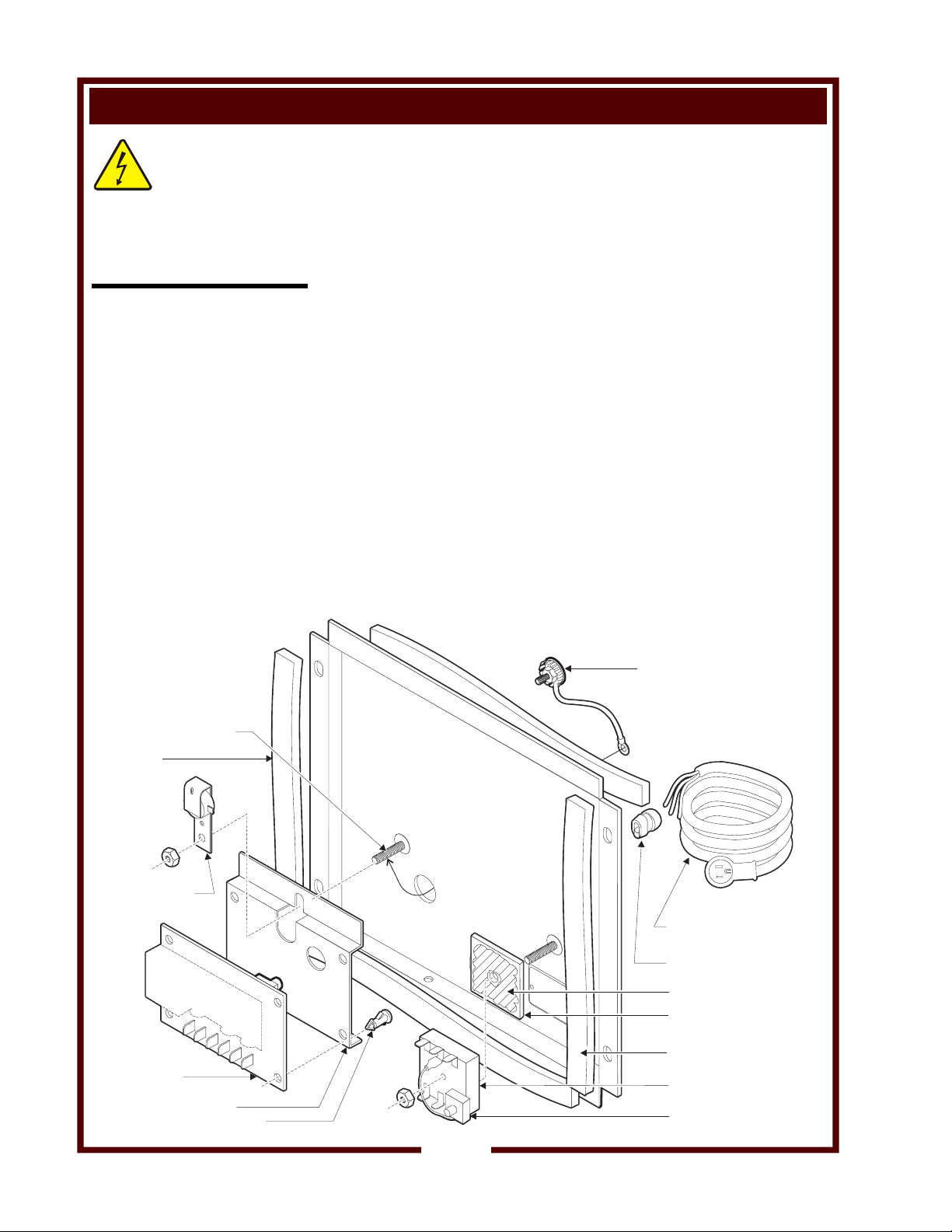
1. Voltage between temperature controller terminals 2 & 3will be
120V any time the power switch (item 66) is turned ON. Absence of
120V indicates power switch OFF or defective, or a wiring or
connector problem.
2. Voltage between TP1 and TP2 will be 120V when the unit is calling
for heat. Absence of 120V, when heating is required, indicates:
a.) Power switch defective or OFF; or,
b.) Temperature controller defective or open temperature probe;
or,
c.) Wiring or connector problem
3. Voltage between TP1 and TP2 will be 120V when the unit is calling
for heat. Failure to heat when 120V is present indicates that the
element being tested is defective.
4. Voltage between temperature controller terminals 1 & 3 will be
120V when the temperature controller is calling for heat. Absence
of 120V, when heating is required, indicates:
a.) Power switch defective or OFF; or,
b.) Temperature controller defective, or
c.) Shorted temperature probe or probe wiring shorted
(check between terminals 4& 5); or,
d.) Wiring or connector problem
5. TP3 and TP4 are found only on waffle bakers equipped with a hi-
limit thermostat. The hi-limit thermostat should be removed and
bypassed to increase the reliability of the waffle baker.
6. Voltage between timer terminals 2& 3is 120V any time the power
switch is ON. Absence of 120V indicates:
a.) power switch defective or OFF; or,
b.) a wiring or connector problem
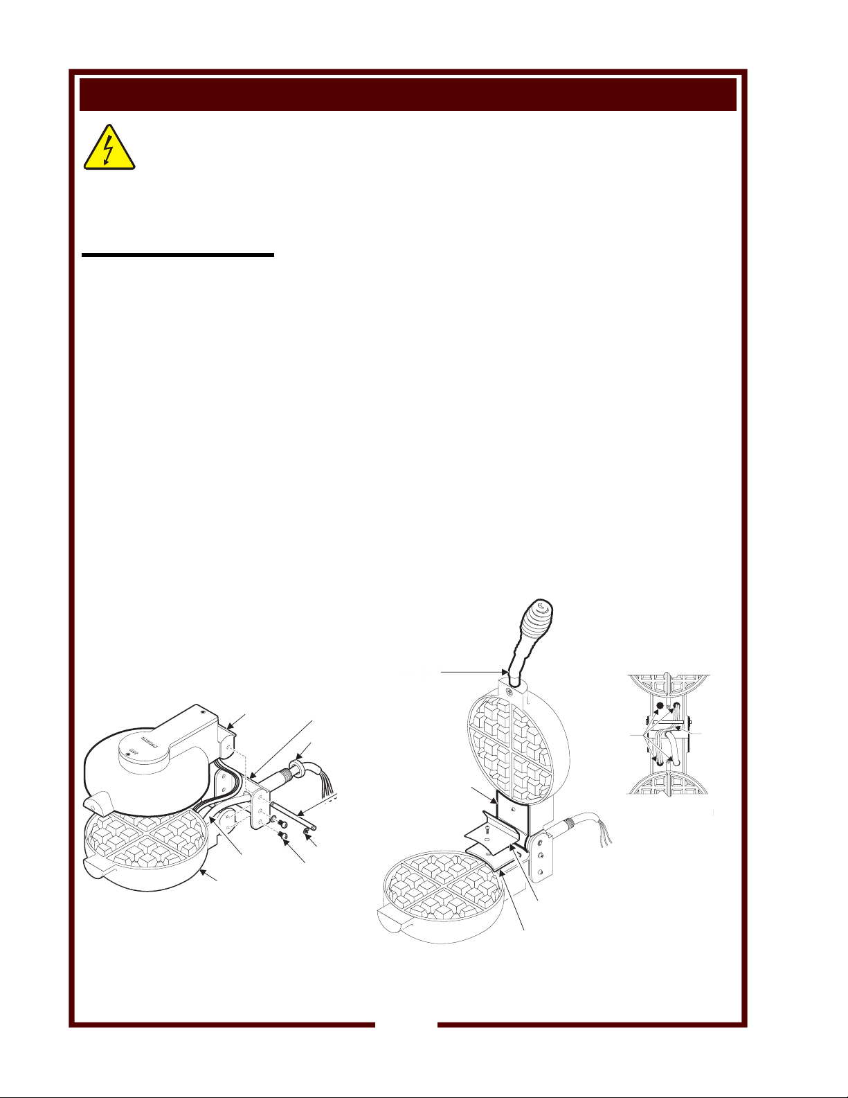
7. Voltage between timer terminals 5& 6is 0V when the microswitch
(item 10) is activated. Any voltage other than 0V indicates a
defective microswitch, or a wiring or connector problem.
8. Voltage between timer terminals 1& 2 is 120V during the cook
cycle. Absence of 120V indicates a defective timer module.
9. An indicator light NOT lit when reading a voltage between timer
terminals 1& 2 is 120V indicates:
a.) loose or defective wiring to the indicator light; or,
b.) defective indicator light
10. Voltage between timer terminals 2& 4is momentarily 120V at the
end of the cook cycle.
Absence of 120V indicates a defective timer module.
CAUTION:
ELECTRIC SHOCK
HAZARD
Live electric circuits may
be exposed during these
procedures. Take necessary
precautions to avoid electric
shock.
CAUTION:
BURN HAZARD
HOT SURFACES
Equipment surfaces may be hot
during these procedures. Take
necessary precautions to
avoid burns.
NOTE: Resistance of the
temperature probe is
typically 5 megohm at room
temperature, with resistance
decreasing as temperature
rises.
• A shorted temperature
probe will cause a
runaway condition.
• An open probe will cause
a continuous OFF
condition.
NOTE:
Newer waffle bakers do not
use a hi-limit thermostat.
Existing hi-limit thermostats
may be safely removed and
bypassed without affecting
the UL approval.
See page 10.

SERVICING INSTRUCTIONS
5
211 502972 SvcManual for BWB-1S Belgian Waffle Bakers
A. CABINET ASSEMBLY
1. Insert the trademark plate from the front. From the rear of the
cabinet, slide retainers over the trademark plate pins. Using a
deep socket, tap the retainers down until they are flush with the
cabinet surface.
2. Attach wires 1, 2, 3 & 4 to the power switch switch. Thread one nut
onto the switch shaft approximately 1/2”, then slide the switch seal
over the switch shaft. Insert the switch from the rear of the cabinet.
Slide the guard, then the on/off plate over the switch shaft. Thread
on and tighten the second nut.
3. Work the seal over the body of the indicator light, then press the
indicator into the cabinet until it pops securely into place.
4. Install the support bracket.
5. Screw four rubber feet into the bottom panel, then install the
bottom panel onto the cabinet.
CAUTION:
ELECTRIC SHOCK
HAZARD
Unplug appliance from
electric power before
removing any panel or
access cover.
WELLS
CABINET
REMOVABLE
DRIP TRAY
SUPPORT BRACKET SEAL
INDICATOR
SWITCH
GUARD
ON/OFF PLATE
SEAL
TRADEMARK PLATE
RETAINER
RUBBER FOOT
BOTTOM
PANEL

SERVICING INSTRUCTIONS (continued)
6
211 502972 SvcManual for BWB-1S Belgian Waffle Bakers
B. BACK PANEL & SOLID STATE CONTROLS ASSEMBLY
1. Apply foam tape to the back panel flange - inside surfaces for the
right, left and bottom; outside surface for the top.
2. Insert the power cord into the strain relief, then install the strain
relief from the outside of the back panel.
3. From the outside, thread the ground wire of the hole plug assembly
thru the large hole in the back panel. Tap the hole plug into place.
4. Press the adjustment module onto terminal 6 of the temperature
controller, then secure it with a dab of silicone sealant. Press the
wire lead of the adjustment module onto terminal 2.
Coat both faces of the heat sink with thermal mastic (heat transfer
compound). Slide the heat sink, then the temperature controller
over the stud closest to the data plate embossing. The adjustment
module should be oriented down and toward the outside.
5. Insert four printed circuit board standoffs into the timer bracket.
Push them until the button head is flush against the inside surface.
Slide the bracket over the stud closest to the large hole, then
secure with two screws from the bottom.
6. Slide the buzzer over the same stud as the timer bracket.
7. Lightly thread the nut onto the stud to retain the buzzer. Upon
wiring the unit, after all ground wires have been attached to this
stud, tighten the nut securely to ensure a positive chassis ground
connection.
CAUTION:
ELECTRIC SHOCK
HAZARD
Unplug appliance from
electric power before
removing any panel or
access cover.
HOLE PLUG
ASSEMBLY
(ATTACH PIGTAIL
TO GROUND STUD)
POWER
CORD
STRAIN
RELIEF
BACK
PANEL
FOAM
TAPE
TEMPERATURE
CONTROLLER
THERMAL
MASTIC
HEAT SINK
TIMER
TIMER BRACKET
PC BOARD STANDOFF
ALL GROUND
WIRES
CONNECT TO
THIS STUD
BUZZER
ADJUSTMENT
MODULE

SERVICING INSTRUCTIONS (continued)
7
211 502972 SvcManual for BWB-1S Belgian Waffle Bakers
C. TOP GRID
1. Prepare grid casting by applying a small amount of anti-sieze paste
to all threaded holes.
2. Feed wires 5, 6 & 20 thru the right feed-thru hole. Attach wires
5 & 6 to the element terminals. Attach wire 20 to the center-most
boss at the front of the casting.
3. Pull the wires back until they have only a small amount of slack.
Seal both sides of both feed-thru holes with hi-temperature silicone
sealant.
4. Install the wiring cover.
D. BOTTOM GRID
1. Prepare grid casting by applying a small amount of anti-sieze paste
to all threaded holes.
2. Set the grids waffle-side down, and with the rear portions touching.
This positions the grids properly for later assembly.
3. Feed the temperature probe leads and wire 10 thru the hi-temp
tubing, then thru the left feed-thru hole.
4. Feed wires 5, 6, & 20 (from top grid) and wires 7 & 8 thru the right
feed-thru hole. Attach wires 5 & 8 to one element terminal, and
wires 6 & 7 to the other element terminal.
5. Set the temperature probe between the two screw bosses with its
round nose pointing to the right. Slide the retainer over the probe.
Install the screws with wires 10 & 20 attached to the center-most
screw boss.
6. Route wires as shown. Pull the wires and hi-temp tubing back until
they have only a small amount of slack. Seal both sides of both
feed-thru holes with hi-temperature silicone sealant.
7. Install the wiring cover.
CAUTION:
ELECTRIC SHOCK
HAZARD
Unplug appliance from
electric power before
removing any panel or
access cover.
HI-TEMP
TUBING
PROBE
RETAINER
PROBE
RETAINER
GRID
TOP GRID BOTTOM GRID

SERVICING INSTRUCTIONS (continued)
8
211 502972 SvcManual for BWB-1S Belgian Waffle Bakers
E. GRID ASSEMBLY
1. Turn and position the grids so that the waffle-sides are facing each
other. Thread the hi-temp tubing thru the shaft of the pivot housing.
Attach the pivot housing to the bottom grid with screws (bottom
hole) and screws with washers (middle hole). Use anti-sieze paste
on the screw threads, but do not tighten the screws yet.
2. Insert the pivot shaft thru the pivot housing and top grid, making
sure wires 5, 6 & 20 are routed between the pivot shaft and the
body of the top grid casting. Secure the pivot shaft with “C” clips
on each end.
3. Verify that the top and bottom grids match at the mating surfaces,
then tighten the screws securing the pivot housing to the bottom
grid.
4. Thread the brass bushing over hi-temp tubing and the shaft of the
pivot housing. Press the bushing all the way against the face of
the pivot housing.
5. Install the handle asembly in the top grid. Use Loctite on the screw
threads.
6. Install the top grid hinge wiring cover, then the teflon drip guide and
bottom grid wiring cover. Use anti-sieze paste on the screw
threads.
7. The top grid should pivot smoothly. Gently bend the upper lip of
the bottom grid hinge wiring cover until the gap between wiring
covers is maintained thru the entire swing of the top grid, and the
top grid closes completely on the bottom grid.
CAUTION:
ELECTRIC SHOCK
HAZARD
Unplug appliance from
electric power before
removing any panel or
access cover.
BOTTOM GRID
TOP GRID
SEAL
FEED-THRU
HOLES W/
HI-TEMP
SILICONE
SEALANT
4 PLACES
ROUTE
THESE
WIRES
UNDER
PIVOT
SHAFT
BOTTOM GRID
HI-TEMP
TUBING
TOP GRID
BUSHING
PIVOT
HOUSING
PIVOT
SHAFT
C CLIP
LOCTITE™
ON THREADS
TEFLON
GUIDE
BOTTOM GRID HINGE
WIRING COVER
TOP GRID HINGE
WIRING COVER
HANDLE
ASSEMBLY

SERVICING INSTRUCTIONS (continued)
9
211 502972 SvcManual for BWB-1S Belgian Waffle Bakers
F. PIVOT BEARING ASSEMBLY
1. The pivot bearing may be out of alignment as it comes from the
box. Tap the collar of the bearing with a plastic hammer until the
axis of the bearing is perpendicular to the base. Attach the pivot
bearing to the inside of the cabinet. The zerk fitting points
downward. Use Loctite on the threads.
2. Looking into the back panel, turn the bearing until the set screws
are at the 10:00 and 2:00 position. Assemble the actuator to the
pivot bearing. The set screws will protrude thru the holes on the
actuator halves. The long arm of the actuator should point down,
with the screws pointing left.
3. Thread the wires of the grid assembly thru the pivot bearing from
the outside, then insert the pivot housing shaft into the pivot
bearing. Thread the actuator nut on the pivot housing shaft using
Loctite on the threads. Tighten the pivot nut until the grid assembly
rotates freely, but latches securely into the detent.
4. If not already present, assemble the support bracket to the cabinet.
Make sure the front of the grid assembly rides smoothly in the
support.
5. Rotate the grid assembly to the COOK position. Align the long arm
of the actuator to point straight down, then tighten the set screws.
6. Using Loctite on the threads, assemble the microswitch to the
switch saddle. Install the switch assembly into the cabinet. Adjust
the position of the microswitch until a single CLICK is heard from
the microswitch as the long arm of the actuator contacts the
microswitch arm, and the grid assembly rotates into the cook
position detent.
CAUTION:
ELECTRIC SHOCK
HAZARD
Unplug appliance from
electric power before
removing any panel or
access cover.
PIVOT HOUSING
(wiring not shown)
BEARING
ACTUATOR
PIVOT NUT
SWITCH
SADDLE
MICROSWITCH
SET SCREWS
LOCATE THRU
HOLES IN
ACTUATOR
LONG ARM OF ACTUATOR
DOWN WHEN IN COOK
POSITION

SERVICING INSTRUCTIONS (continued)
10
211 502972 SvcManual for BWB-1S Belgian Waffle Bakers
G. BYPASS HI-LIMIT THERMOSTAT
1. The hi-limit thermostat in this Belgian Waffle Baker has been found
to be unnecessary. Wells BWB-1S has been tested and approved
by UL for use without the hi-limit thermosat.
2. All units requiring service, whether in or out of warranty, should
have the hi-limit thermostat bypassed.
3. With the power cord unplugged, remove wires 7 & 19 from the
hi-limit thermostat (located in the bottom grid).
4. Cut the push-on terminals from wires 7 & 19, as close to the
terminals as possible.
5. Remove 1/2” of insulation from the ends of wires 7 & 19. Connect
the wires together using a ceramic wire nut of the appropriate size.
6. Plug the waffle baker in, and test for proper operation.
CAUTION:
ELECTRIC SHOCK
HAZARD
Unplug appliance from
electric power before
removing any panel or
access cover.
IMPORTANT:
Wells BWB-1S has been
tested and approved by UL
for use without the hi-limit
thermosat. The hi-limit
thermostat may be removed
from existing units and its
circuitry bypassed without
compromising the UL listing
for this appliance.
HI-LIMIT
THERMOSTAT CERAMIC
WIRE NUT
7
19 19
7
BOTTOM GRID
7
19
HI-LIMIT THERMOSTAT
DELETE and BYPASS
WIRING COVER

WIRING DIAGRAM
11
211 502972 SvcManual for BWB-1S Belgian Waffle Bakers
WIRING DIAGRAM FOR BWB-1S
120 VAC
123
45
N.C.
N.O.
COM
123456
white
black
green
L1
L2
1
2
10
17
11
14
16 9
15
TIMER
POWER CORD
CONNECTOR (2)
POWER
SWITCH
TEMPERATURE
CONTROLLER
4
3
7
8
12
20
6
13
TEMP.
SENSOR
LOWER
HEATING
ELEMENT
UPPER
HEATING
ELEMENT
5
MICRO
SWITCH
BUZZER
INDICATOR
LIGHT
VOLTS AMPS 1Ø
120 7.5 50/60 Hz p/n 44867 Rev.D
HI-LIMIT
THERMOSTAT
older units only
(remove & bypass)
19

EXPLODED VIEW
12
211 502972 SvcManual for BWB-1S Belgian Waffle Bakers
WELLS
ASSY, HOLE
PLUG 61064
CONTROLLER
TEMP 64276
SEALANT, THERMO
COMPOUND
66160 (2 gm)
BUZZER
120V 60259
TIMER, ELECTRONIC
BWB-1 63179
STAND-OFF PC
BOARD 63565
STRAIN RELIEF
51217
POWER CORD
120V 15A 55539
NEMA 5-15P 4’
SEAL, O-RING 9/16”
64890
LIGHT, SIGNAL
RED 60758
BRACKET, FRONT
SUPPORT 62028
RETAINER,TRADEMARK
51038 (pk 10)
TRADRMARK
PLATE 51239
GUARD, SWITCH
65174
PLATE, SWITCH
ON-OFF 53192
SWITCH, POWER
64904
RUBBER FEET
21657 (pk 4)
DRIP TRAY
BWB-1 21107
BWB-1S CABINET

EXPLODED VIEW
211 502972 SvcManual for BWB-1S Belgian Waffle Bakers
13
BWB-1S GRIDS
CAUTION
HOT
CAUTION
HOT
CAUTION
HOT
62029
COVER, LOWER
62029
RETAINER, THERMO
PROBE 64885
THERMOPROBE
64872
HEATING ELEMENT
LOWER GRID 62007
SLEEVING, HI-TEMP
8.5” BWB-1 64201
COVER, WIRING
LOWER 62031
COVER, WIRING
UPPER 62023
HOUSING ASSY
PIVOT 62006
MICROSWITCH
120V 15A 64887
BEARING
BWB-1 62232
SPACER, NYLON
BWB-1 62035
PIN, PIVOT BWB-1
UPPER HINGE
62018
RETAINING RING
50222 (pk10)
HEATING ELEMENT
UPPER GRID 62008
ASSY, HANDLE
BWB-1 62257
COVER, UPPER
62024
Other manuals for BWB-1S
4
Table of contents
Other Wells Kitchen Appliance manuals