Wellsaw 1220G-72D Installation and operation manual

1220G-72D
MODEL
Special Purpose Bandsaw
Built better to work stronger and last longer
2829 N. Burdick St. Kalamazoo, MI 49004
Phone: 269-345-1132 Fax: 269-345-0095
www.wellsaw.com
ick
S
t. Kalamazoo, MI 49004
345-1132 Fax: 269-345-0095
Rev 170816
Parts List
and
Operating & Maintenance Manual

2

3

4

5
Warranty Information................................................2
Receiving and Installation.........................................2
Safety Instructions....................................................3
Specifications ...........................................................5
Standard Features....................................................5
Troubleshooting........................................................6
Startup & General Information..................................8
Operation & Maintenance.........................................8
Periodic Inspection.................................................10
Adjustment & Repair...............................................10
Recommended Service Kit..................................... 11
Parts Drawings & Parts Lists
Base Assembly.......................................................12
Frame Assembly.....................................................14
Frame Guards ........................................................16
Hydraulic System....................................................18
Blade Guides..........................................................20
Wheel Plate / Frame Roller ....................................22
Micro Switch...........................................................24
Electrical.................................................................26
Electrical Schematic...............................................29
TABLE OF CONTENTS
Specifications
Model 72” Capacity
Capacity 78” H (1981 mm)
85” W (2159 mm)
33.75 Throat (857 mm)
Blade Size 1.5” x .050” x 31’-3”
Maximum Height
Frame Full “Up” 166” (4216)
Floor Space Required 94” x 174.5”
(2388 mm x 4432 mm)
Shipping Weight 5000 lbs (2273 kg)
Shipping Dimension 175” W x 118” H x 94” D
(4445 x 2998 x 2388 mm)
Wet Cutting System Unist
Motor 5 HP (3.73 KW)
Blade Speeds 80, 135, 210 SFPM; selection by stepped pulley
Drive System Cone Drive
Parts Manual
Wellsaw Model 12 20-GD
Serial number ______

6

7

8
START UP
Upon receipt of machine, uncrate and check all parts. In case of
loss or damage, file Proof of Loss Claim with carrier.
Remove rust preventive from vertical posts using mineral spirits.
Coat with light oil.
CAUTION: Do not grease upright posts!
GENERAL INFORMATION
The cutting head, or frame of this machine is raised and lowered
by the hydraulic unit in the base.
Working in conjunction with this assembly are the electrical units
composed of the control cabinet, front mounted controls, limit
switches, blade micro-switch, pump motor (1 HP), and blade drive
motor (5 HP)
HYDRAULIC SYSTEM
1. PUMP - positive displacement, rotary type. Forces oil into
lifting cylinders.
2. TANK - should contain 10 gallons of Mobil DTE 25 Hydraulic
Oil or equivalent
3. CYLINDER & PISTON - steel cylinder and piston with neo-
prene cup.
4. SOLENOID VALVE - regulates flow of oil through line as blade
pressure increases and decreases, actuated by blade micro-
switch.
5. NEEDLE VALVE - governs discharge of oil from cylinder as
frame lowers.
ELECTRICAL SYSTEMS
1. LIMIT SWITCHES - Upper limit switch stops upward travel of
cutting head at predetermined height set by trip collar. Lower
limit switch stops blade motor at end of cut .
2. BLADE MICRO-SWITCH An automatic device is actuated
by pressure on the blade and controls the solenoid valve to
maintain constant downward blade force. It also activates an
indicator light on top of the front mounted controls.
3. PUMP MOTOR - 1 HP
4. BLADE DRIVE MOTOR - 5 HP "V" belt drive to gear case.
Standard speeds: 80 FPM, 135 FPM, 210 SFPM.
5. FRONT MOUNTED CONTROLS - push buttons for blade mo-
tor, feed, emergency stop.
OPERATING INSTRUCTIONS
1. Remove wheel covers and install blade. Be sure that teeth
are pointing toward the drive end of the machine. This is the
proper direction of blade travel through the cutting area.
2. Raise frame by pressing RAISE button which starts the hy-
draulic pump. When frame reaches a position so that the
blade is about 1" above stock to be cut, push STOP button
which will stop and hold the frame at this point.
3. Move upper set collar to desired height on control rod and
lock in position with thumb screw.
4. Place stock in approximate cutting position. Press LOWER
button to lower the frame. If more rapid traverse in lowering
the frame is desired, this can be accomplished by turning the
indicator head in a counter-clockwise direction. When blade is
about 1/ 8” above stock, press LOWER stop button, stopping
and holding the frame. Measuring from blade tooth, adjust
stock to exact cutting position and secure stock.
5. With stock in proper position for cutting and clamped, push
BLADE START button to start blade drive motor and then
push LOWER button, which energizes blade micro-switch
and solenoid valve circuit. The machine will then start its con-
trolled cutting action. The blade will automatically stop when
the frame reaches the lower limit switch.
6. When cutting begins, notice the action of the blade micro-
switch located in casting above the blade on the idle end
guide assembly.
In case of excessive feed, the tension of the spring is quickly
overcome. The excessive pressure on the blade raises the stem
linkage that operates the blade micro-switch which closes the so-
lenoid valve. This stops the downward travel of the saw frame.
As the cutting action of the blade removes material to relieve this
excessive pressure, the micro-switch will function and open the
solenoid valve for an instant until pressure again becomes exces-
sive. This can be readily noticed by the operator due to the jumpy
action of the saw frame exerting excessive pressure on the blade
as the solenoid valve opens and closes.
Decrease feed at indicator head until cutting and feed are equal-
ized. Insufficient feed is easily recognized as the blade will do very
little cutting, if any, due to the lack of cutting pressure.
When correct feed is being employed, the blade will cut steadily
and the micro-switch will function occasionally to open and close
the solenoid valve. The amber light on the top of the front mount-
ed control box indicates that the saw is feeding. When the solenoid
valve closes, the light goes out.
After a correct feed has been established, the position of the indi-
cator head should be noticed, and this location maintained while
cutting similar size and type material. Always keep the indicator
head WITHIN CUTTING LIMITS, as shown on dial, during actual
cutting operations.
We call your attention to the adjusting knob on the blade micro-
switch assembly. While it may be necessary at times to adjust the
spring pressure when radically different materials are to be cut, for
instance, from bar stock to thin wall tubing, the operator should not
make a habit of changing it casually.
As the spring is compressed, more pressure must be exerted
against the blade before the micro-switch functions. The micro-
switch spring controls the pressure against the blade and consid-
erable discretion should be used before making any change (See
Adjust Blade Micro-Switch, page XX)
During the cutting cycle, when frame is in downward travel, all op-
erations can be stopped immediately by pressing STOPor BLADE
STOP buttons or EMERGENCY STOP button. When in upward
travel, this can be accomplished by pressing the STOP button.
BLADE GUIDES
The blade guides are arranged to hold the blade in alignment both
vertically and horizontally.
Before making any adjustments, always try a new blade to be sure
that the old blade was not causing the difficulty (See Blade Guide
Alignment, page XX).
BLADE BRUSHES
Brushes should be cleaned frequently in kerosene and reversed to
take advantage of both rows of bristles.
For best results, replace worn, filled or sticky brushes with new
ones. In bolting brushes to angles, be sure wire bristles are bent
in the same direction as the blade travels.

9
BLADES
Blades for this machine are furnished in 2/3, 4/6, and 8/12 teeth
per inch. 2/3 or 6/8 teeth per inch blades should be used when
solid stock are being cut. 8/12 blade should be used for cutting
tube bundles.
Special purpose blades are also available.
SPEED SELECTION
Saws are equipped with step pulleys, which provide a selection 80
FPM, 135 FPM and 210 FPM speeds.
Use the fast speed to cut thin-walled metal, tubing, thin channels,
aluminum, thin brass, or any metal that will not burn the teeth. Use
the medium speeds on general cutting, such as cold rolled, ma-
chine steels, heavy channels, etc. Use the slow speed for cutting
nickel steels or any metals which require a slow speed on a lathe.
Brass should always be cut with a blade which has not previously
cut other metal.
If teeth wear off unusually fast, use slower speed. ALWAYS KEEP
THE BLADE TIGHT AND FLUSH AGAINST THE FLANGE OF
THE BAND WHEELS (See wheel pitch adjustment instruc-
tions, page XX)
BELT
Proper adjustment of the “V” belt is important to prevent overheat-
ing of the motor. Be sure the belt guard is closed after changing
blade speeds.
PREVENTIVE MAINTENANCE
The proper performance and service life of every machine de-
pends on how well it is maintained. The following should become
a regular routine of operations.
Clean & Lubricate Exposed Surfaces
1. Wipe exposed surfaces free of dirty oil, chips and dirt.
2. Apply a thin coat of oil, Symbol 2190TEP, or equivalent to
machined surfaces.
Inspect Gear Case Lubricant Every 6,000 hours
1. De-energize circuit. Tag “OUT OF SERVICE”.
2. Remove gearcase cover.
3. Use Texico Marfax ‘0’ on the gears.
4. Remove excess lubricant.
5. Reinstall gearcase.
6. Remove safety tag. Energize circuit.
Inspect Hydraulic Oil Level
1. De-energize circuit. Tag “OUT OF SERVICE”.
WARNING: CUTTING HEAD SHALL BE AT LOWEST ETREM-
ITY WHEN INSPECTING OIL LEVEL
2. Locate site gauge on the hydraulic tank.
3. Inspect oil level. Proper oil level is 1” from top of tank.
4. Remove safety tag. Energize circuit.
Clean Coolant Reservoir
1. De-energize circuit. Tag “OUT OF SERVICE”.
2. Remove and clean chip pan.
3. Remove coolant.
4. .Remove residue, sediment, and sludge from reservoir.
5. Clean coolant pump.
6. Reinstall chip pan.
7. Fill coolant reservoir to operating level.
8. Remove safety tag and energize circuit.
9. Return cooling systems to normal operation.
Inspect Flexible Hoses & Fittings
1. Inspect hoses for cracks, breaks and deterioration.
2. Inspect hoses for chafing or evidence of unusual wear
3. Inspect fittings for tightness.
Inspect Drive Belt For Wear
1. De-energize circuit. Tag “OUT OF SERVICE”.
2. Remove covers for access to belt.
3. Inspect belt for deterioration.
4. Depress belt half-way between pulleys. Belt should depress
1/2” to 3/4”.
CAUTION: A BELT THAT IS TOO TIGHT WILL DAMAGE
BEARINGS
5. Remove safety tag. Energize circuit.
Provide Hydraulic Oil Sample For Analysis
1. De-energize circuit. Tag “OUT OF SERVICE”.
NOTE: CLEANLINESS OF TOOLS AND EQUIPMENT IS ES-
SENTIAL FOR PROVIDING TRUE SAMPLE
2. Operate machine 5-8 minutes to allow a true sample to be
drawn after liquid is mixed; stop machine.
3. Fill sample bottle from hydraulic reservoir.
4. Tag sample bottle to identify equipment, and location.
5. Deliver to oil/water laboratory.
6. Renew hydraulic oil when one or more of the following limits
is exceeded:
WATER: 0.001 %
SEDIMENT: 0.1 %
ACID TEST: Indicates Positive
Clean Oil Line Screen (Part #100237-002)
To clean hydraulic line oil screen, which is located at the base of
the machine between the lifting cylinders. Lower frame to remove
all pressure from hydraulic lines. The screen can then be removed
and cleaned by unscrewing the hex nut.
Clean, Inspect & Lubricate Wheel Ball Bearing
1. De-energize circuit. Tag “OUT OF SERVICE”.
2. Remove wheel covers.
3. Remove cutting blade.
4. Remove jamnut and hexnut.
5. Remove band Idler Wheel and Drive Wheel.
6. Remove ball bearing.
7. Clean ball bearing.
8. Clean Idler wheel and drive wheel hub.
9. Inspect ball bearing for rough turning and head discoloration.
10. Pack ball bearing with grease, VV-G-632, Type B, Grade 2.
11. Reinstall ball bearing.
12. Reinstall band idler wheel and drive wheel.
13. Reinstall hexnut and jamnut.
14. Repeat steps 4 through 13 for other wheel bearings.
15. Reinstall blade.
16. Reinstall wheel covers.
17. Remove safety tag. Energize circuit.

10
6. Move the lower limit collar until the switch moves enough to
activate the switch. When the contacts close you will hear a
click.
Blade Force Limit (Spring Loaded Blade Micro-
Switch, Reference page XXX)
Blade Force Limit is set by the knob on the Guide Arm. This sets
a spring force on the blade back-up bearing to interrupt excessive
frame feed, and is indicated by the LOWER light blinking off during
a cut. A setting of “3” will normally protect the blade from exces-
sive force when the feed rate is set so the LOWER light remains
on through the cut. This setting may be changed as needed for
particular cutting applications. For a few applications at slow feed
rates, the blade force switch may be set to control feed rate by
interrupting down feed during the cut.
Lubrication
Correct and adequate lubrication is a very important factor in de-
termining the life and service of your machine. It is essential that
all dust, dirt, chips, etc. are thoroughly removed before lubricating
the saw. The following lubrication recommendations cover usual
applications. Heavy use and hostile environments may indicate
more frequent lubrication for best saw performance.
Ring Gear, Drive Pinion
1. Inspect monthly.
2. Use Lubriplate grease 130-A or equivalent.
3. Viscosity at 100°F: SUS750-800.
4. Military Specification: Mil-G-46003
Gear Case
1. Inspect after 3 years (6,000 hours).
2. Grease - Texaco Marfax Grade “0” or equivalent.
3. Viscosity at 100°F:SUS 4125.
4. Military Specification: None
Hydraulic Tank
1. Inspect annually. Drain and replace every 5 years (10,000
hours).
2. Fill with Mobil DTE 25 or equivalent.
3. Viscosity at 100°F: SUS 220.0
4. Military Specification: None
Motor
1. Inspect annually. Re lubricate every 2 years (4,000 hours) 1
to 2 full strokes.
2. Use Shell Dolium R or equivalent.
3. Viscosity: Heavy Grease, Drop Point 219° C
4. Military Specification: None
Recommended Service Kits for 2 Years
As Insurance Against Downtime
20 100406-002 Bearing Blade Guide
4 100403-005 Bearing - Drive & Idle Wheel
1 100067-021 “V” Belt - Blade Motor
12 M-426 Blade Brushes
1 370277 Ring Gear, Steel
1 102037 Ring Gear, Cast Iron
1 105721 Drive Pinion
1 100543 Micro-Switch, Blade Pressure
1 100577-005T Replacement Bulb, Frame Feed
Light
1 100249-002 Coolant Pump
2 100628-006 Fuse, 10 amp FNM-10
2 100628-021 Fuse, 15 amp FNM-8
3 100628-020 Fuse, 15 amp TRS-15R
1 G-183 Roller Support, Idle End
1 102054 Roller Support, Drive End
1 F-096A Intermediate Gear, Cast Iron
12 105718-001 Shear Key, Brass

11
Renew Hydraulic Oil
1. Lower head to full down position to facilitate draining of hy-
draulic reservoir.
2. De-energize circuit. Tag “OUT OF SERVICE”.
3. Remove drain plug and drain oil.
4. Reinstall drain plug.
5. Remove filler cap.
6. Fill reservoir to proper level with MOBIL DTE 25 Hydraulic Oil
or equivalent. The tank will hold approximately 10 gallons.
7. Remove safety tag. Energize circuit.
8. Return saw to normal operating condition.
PERIODIC INSPECTION
Frequency
Weekly Clean and lubricate exposed surfaces
Check drive belt for proper tension
Inspect RING GEAR lubricant.
Inspect hydraulic oil level
Monthly Lubricate horizontal bandsaw.
Quarterly Clean coolant reservoir.
Inspect flexible hoses and hose fittings.
Semi Annually Inspect drive belt for wear.
Provide hydraulic oil sample or analysis.
Clean, inspect and lubricate wheel ball
bearing.
Annually Sound & tighten foundation bolts.
Inspect gear box assembly.
As Required Renew hydraulic oil.
NOTE: REPLACE HYDRAULIC OIL WHEN DIRECTED AS A
RESULT OF THE OIL ANALYSIS AND AFTER OVERHAUL
ADJUSTMENT & REPAIR
Adjust Wheel Pitch
1. De-energize circuit. Tag “OUT OF SERVICE”.
2. Loosen blade tension.
NOTE: MOST WHEEL PITCH ADJUSTMENTS CAN BE MADE
BY ADJUSTING THE IDLE END WHEEL PLATE FIRST.
3. Loosen and tighten opposing wheel pitching screws 1/2 turn
as required to change blade tracking on wheel.
4. Re-tension blade.
5. Energize and run blade to verify that blade tracks on wheel
properly, touching wheel flange but not rubbing.
6. Remove safety tag.
Adjust Blade Micro-Switch
1. To check operation of the switch remove control cover (Item
#14XXX). Now turn off the feed valve and press the “Lower”
button with the operation selector in setup. The lower light
should be on. Depress the switch plunger and the lower light
should go off.
2. If the “Lower” light did not go on when the “Lower” button was
pushed, check to see if stud (Item # 27xxx) is holding the
switch plunger in.
3. If the stud is holding the switch plunger in, check for sticking
mechanism then adjust the stud to activate the switch with
.006 gap.
4. If the stud is not holding the switch plunger in and the “Lower”
light does not come on when the “Lower” button is pushed,
then the switch will need to be replaced. To verify this condi-
tion, check the switch with a continuity light.
Blade Force Settings Are:
Position No: 1110 lbs of force to close solenoid
1-1/2 120 “ “
2130 “ “
2-1/2 140 “ “
3150 “ “
3-1/2 160 “ “
4170 “ “
4-1/2 180 “ “
5190 “ “
5-1/2 200 “ “
Blade Guide Adjustment
1. The blade should travel from the idle wheel to the drive wheel
without distortion.
2. The blade guides should be perpendicular to the top of the
channel. Using a square, adjust each guide.
a. Place a flat, preferably ground, piece of steel on the top of
the channel and, using a square, adjust each guide.
b. Check the side bearings to be sure that they are snug
against the side of the blade. Adjust the eccentric roller
axle as needed.
Gear Box Repair
1. Remove gear box from saw.
2. Remove four machine screws holding gear box together.
3. Separate gear box by carefully prying castings apart at loca-
tion near pulley shaft.
CAUTION: DO NOT USE EXCESSIVE FORCE
4. Once the gear box is open, the internal parts may be inspect-
ed for wear.
5. Liquid plastic gasket is used to seal the gear case (Locktite
#51580).
6. Grease -Texaco Marfax ‘0’ or equivalent.
NOTE: THE SHAFT IS HELD IN PLACE BY A SNAP RING BE-
LOW THE DRIVE GEAR. RE-MOVE PINION TO ACCESS SNAP
RING.
Replace Brass Shear Key In Drive Pinion
1. De-energize circuit. Tag “Out Of Service”.
2. Remove the two flat head socket screws.
3. Remove retainer cover (Part #105719).
4. Remove old brass key (NOTE: A 6-32 tapped hole has been
drilled into the brass key to assist in its removal.)
5. Be sure all pieces of old brass key have been removed.
6. Be sure that the pinion rotates freely around the pinion shaft.
Asmall amount of grease may be applied to the shaft if need-
ed.
7. Insert new brass Key (Part #105718-001).
8. Re-install retainer cover and screws.
9. Check ring gear for proper lubrication.
10. Remove safety tag. Re-energize circuit.
Adjusting Frame Limit Switches
1. Adjust the top actuating collar on the support rod to maximum
height.
2. Raise the frame so that the teeth on the blade are approxi-
mately 1” above the material to be cut.
3. Raise the actuating collar until the collar moves the switch
arm enough to activate the switch. When the contacts close
you will hear the switch click.
4. Secure the collar in place at this point by tightening the thumb
bolt in the actuating collar.
5. To set the lower limit, lower the frame until the teeth on the
saw blade are 1/8” below the material to be cut.

12
1
2
3
4
5
7
8 9
6
10
11
12
13
14
15
14
16
17
8
6
519
Base Assembly
Base Assembly

13
1 105118-001 BASE WELDMENT
2 100690-027 CONTROL BOX
3 100013-006 CAP SCREW, BUTTON HD,
1
4
-20 X 3/8
4 105110 LIMIT SWITCH ACTUATING BAR
5 100004-038 CAP SCREW, HEX HD,
1
2
-13 X 2
6 100025-005 LOCK WASHER,
1
2
7 100042-002 THUMB SCREW,
1
4
-20 X
1
2
8 105111 LIMIT SWITCH ACTUATING COLLAR (3 REQ'D)
9G-082 STOP BLOCK (2 REQ'D)
10 105723 HYDRAULIC CYLINDER (2 REQ'D)
11 102684 UPPER FRONT GUARD
12 104117 MIDDLE FRONT STATIONARY GUARD
13 102683 BOTTOM FRONT GUARD
14 102681 BACK STATIONARY GUARD (2 REQ'D)
15 102682 BACK STATIONARY GUARD
16 105109-001 ACTUATING BAR WELDMENT
17 105109-002 ACTUATING BAR WELDMENT
18 100053-036 SPRING PIN,
1
4
X 2
19 100029-006 FLAT WASHER,
1
2
Base Assembly
Base Assembly

14
1
10
13
14
4
25
23
22
24
21
20
19
18
16
17
29
2
26
27
56
78
9
8
7
11
12
15
3
28
Frame Assembly
Frame Assembly

15
1 105737-001 FRAME AND ROLLER SUPPORT WELDMENT
2 G-001 FRAME ROLLER
3 103145-005 BAND WHEEL ASSEMBLY (INCLUDES 7-10)
4 100019-008 HEX JAM NUT,
3
4
-10
5 100029-009 FLAT WASHER,
3
4
6 H-048-002 SPACER
7 100421-002 BEARING
8 100068-004 SNAP RING
9 H-048-001 SPACER
10 C-103145-005 BAND WHEEL
11 H-035 WHEEL AXLE
12 100065-010 HEX NUT, 1"-14
13 100782-006T LIMIT SWITCH
14 105108 LIMIT SWITCH BRACKET
15 100004-018 CAP SCREW, HEX HD,
5
16
-18 X 1
16 100898-001 MOTOR BASE
17 100835-022 MOTOR
18 155236 GEARBOX
19 100175 LEVELING SCREW
20 100008-081 CAP SCREW, SOCKET HD,
1
2
-13 X 4
1
2
21 105792 BELT GUARD
22 100141-013 TIMING PULLEY
23 100140-007 TIMING BELT
24 100141-012 TIMING PULLEY
25 105782 BAND WHEEL ADAPTER
26 100008-032 CAP SCREW, SOCKET HD,
1
2
-13 X 1 1/2
27 100004-030 CAP SCREW, HEX HD,
3
8
-16 X 1
1
2
28 100025-003 LOCK WASHER,
3
8
29 103145-008 BAND WHEEL, CONE DRIVE
30 100025-002 LOCK WASHER,
5
16
Frame Assembly
Frame Assembly

16
1
2
3
4
4
5
6
79
3
12
13
14
16
15
7
10
11
8
Frame Guards
Frame Guards

17
1 105113 ROLLER GUARD
2 103185 ROLLER GUARD
3 103119 ROLLER GUARD
4 103139 ROLLER GUARD
5 105128 WHEEL COVER, IDLE END
6 100104-001 HANDLE (2 REQ'D)
7 100155-001 MACHINE SCREW, TRUSS HD, 1
4-20 X 1
2
8 100013-006 CAP SCREW, BUTTON HD, 1
4-20 X 1
2
9 105114 ROLLER GUARD
10 105129 BLADE GUARD BACK
11 100063 THUMB SCREW
12 105115 ROLLER GUARD
13 105710-001 DOOR SUPPORT
14 9512K63 BALL STUD, LONG
15 9416K137 GAS SPRING, STEEL (2 REQ'D)
16 9512K73 BALL STUD, 5
16 -18
Frame Guards
Frame Guards

18

19

20
1
2
3
4
5
5
7
7
8
9
8
10 11
12
14
13
15
22
16
17
14
13 14
27
27
23
24
25
26
28
29
32
35
19 20 21
36
37
38
30 31
33
19
20
21
18
13
6
14 13
14
34
34
Blade Guides
Blade Guides
Table of contents
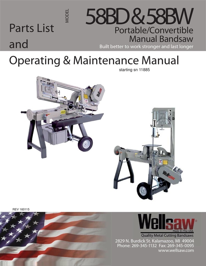
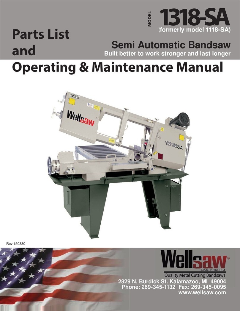
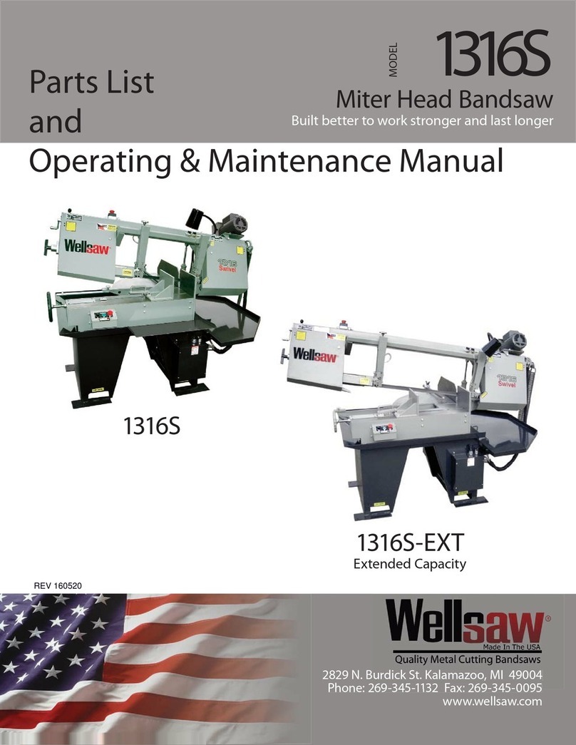
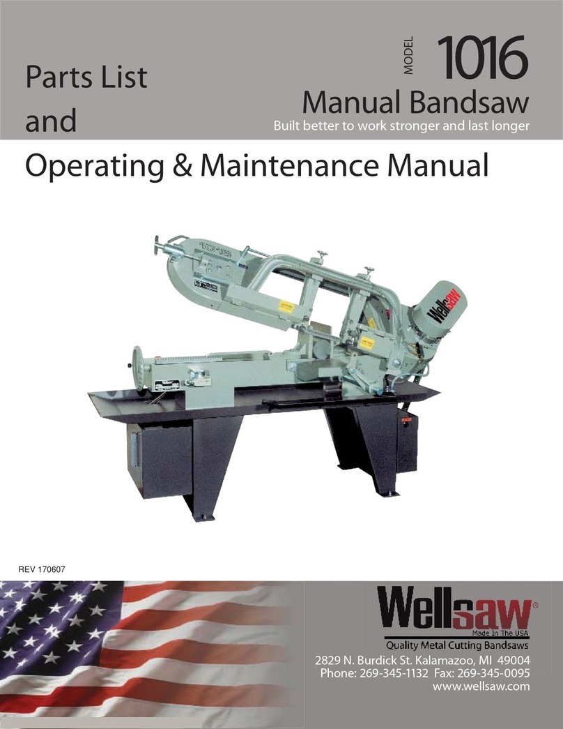
Other Wellsaw Saw manuals

Wellsaw
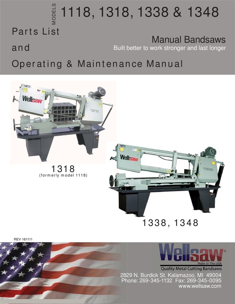
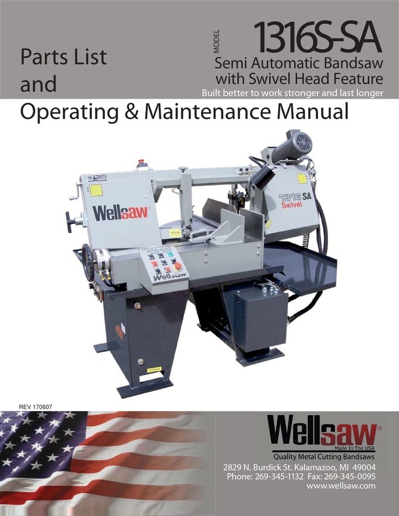
Wellsaw 1316S Installation and operation manual

Wellsaw
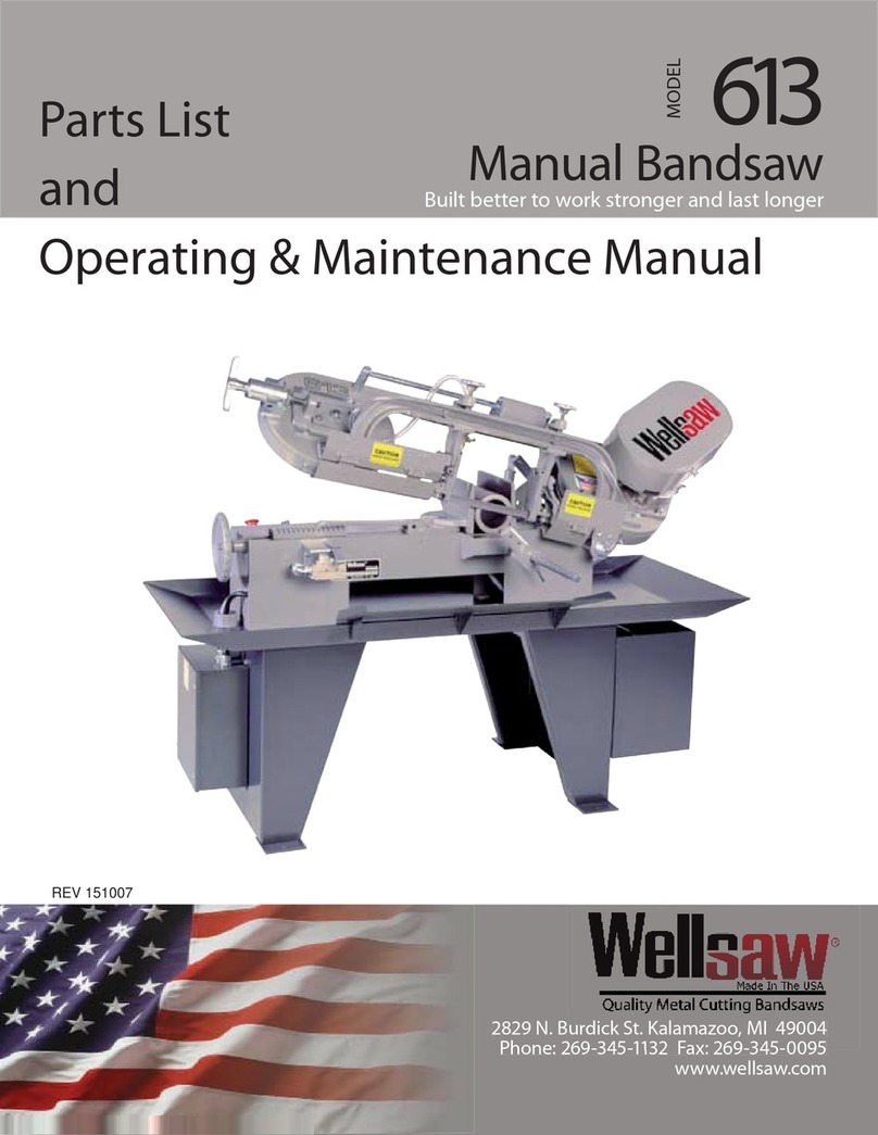
Wellsaw 613 Installation and operation manual

Wellsaw
Wellsaw V-20F Installation and operation manual

Wellsaw
Wellsaw 1270 User manual

Wellsaw
Wellsaw 1318 User manual

Wellsaw
Wellsaw 8 Installation and operation manual

Wellsaw
Wellsaw 1016 Installation and operation manual

Wellsaw
Wellsaw 57 Installation and operation manual

Wellsaw
Wellsaw 1316S-SA Installation and operation manual

Wellsaw
Wellsaw 1318 -SA Operating instructions