Pearl Abrasive PA-7PRO Owner's manual

serial number -
MODEL PA-7PRO™ TILE SAW
OWNER’S/OPERATOR’S MANUAL
Caution! Read Safety and General Instructions carefully before using saw for the first ti e.
You should record the Seri l Number of your Tile S w on this
Owner’s/Oper tor’s M nu l nd on the W rr nty C rd.
The Warranty Card ust be sent back with all the required
pertinent infor ation for the warranty to take effect.
P e a r l A b r a s i v e C o . 2 . 1 T I L E S A W
REV. 1

TABLE OF CONTENTS
i. geNeRaL SaFeTY RULeS FOR aLL pOWeR TOOLS . . . . . . . . . . . . . . . . . . . . . . . . . . . . . . . 3
ii. SYMBOLS . . . . . . . . . . . . . . . . . . . . . . . . . . . . . . . . . . . . . . . . . . . . . . . . . . . . . . . . . . . . . . . . . . . 4
iii. FeaTUReS . . . . . . . . . . . . . . . . . . . . . . . . . . . . . . . . . . . . . . . . . . . . . . . . . . . . . . . . . . . . . . . . . . . 5
i . SpeCiFiCaTiONS . . . . . . . . . . . . . . . . . . . . . . . . . . . . . . . . . . . . . . . . . . . . . . . . . . . . . . . . . . . . . 5
. UNpaCKiNg . . . . . . . . . . . . . . . . . . . . . . . . . . . . . . . . . . . . . . . . . . . . . . . . . . . . . . . . . . . . . . . . 6
i. iNSTaLLaTiON aNd OpeRaTiON . . . . . . . . . . . . . . . . . . . . . . . . . . . . . . . . . . . . . . . . . . . . . 6
ii. pROpeR BLade USe . . . . . . . . . . . . . . . . . . . . . . . . . . . . . . . . . . . . . . . . . . . . . . . . . . . . . . . . . . 8
iii. SaFe OpeRaTiNg pRaCTiCeS FOR TiLe SaW. . . . . . . . . . . . . . . . . . . . . . . . . . . . . . . . . . . . 9
ix. CaRe aNd MaiNTeNaNCe . . . . . . . . . . . . . . . . . . . . . . . . . . . . . . . . . . . . . . . . . . . . . . . . . . 12
x. eLeCTRiCaL MOTOR SpeCiFiCaTiONS . . . . . . . . . . . . . . . . . . . . . . . . . . . . . . . . . . . . . . . . 14
xi. RepLaCeMeNT paRTS LiST . . . . . . . . . . . . . . . . . . . . . . . . . . . . . . . . . . . . . . . . . . . . . . . . . . . 15
xii. TROUBLeSHOOTiNg . . . . . . . . . . . . . . . . . . . . . . . . . . . . . . . . . . . . . . . . . . . . . . . . . . . . . . . . 18
xiii. aCCeSSORieS aNd paRTS . . . . . . . . . . . . . . . . . . . . . . . . . . . . . . . . . . . . . . . . . . . . . . . . . . . 18
xi . THe RigHT BLadeS dOeS THe RigHT JOB. . . . . . . . . . . . . . . . . . . . . . . . . . . . . . . . . . . . . 19
x . HOW TO ORdeR paRTS. . . . . . . . . . . . . . . . . . . . . . . . . . . . . . . . . . . . . . . . . . . . . . . . . . . . . 19
page

– 3–
i. GENERAL SAFETY RULES FOR ALL POWER TOOLS
1. Know your power tool - read owner’s/operator’s manual carefully. Learn its applications and limitations as
well as the specific potential hazards unique to this tool.
2. Keep guards in place - and in working order.
3. round all tools - if tools are equipped with three prong plug, it should be plugged into a three-hole electrical
receptacle. If an adapter is used to accommodate a two-prong receptacle, the adapter lug must be attached
to a known ground. Never remove the third prong.
4. Remove wrenches - Form a habit of checking to see that adjusting wrenches are removed from tool before
turning it “on”.
5. Keep work area clean. Cluttered areas and benches invite accidents.
6. Do not use in dangerous environment. Do not use power tools in damp or wet locations, or expose them to
rain. Keep work area well lighted. Do not use tool in the presence of flammable liquids or gasses.
7. Keep children and visitors away. All children and visitors should be kept at a safe distance from work area.
8. Make workshop childproof with padlocks, master switches or by removing starter keys.
9. Do not force tool. It will do the job better and be safer at the rate for which it was designed.
10. Use right tool. Do not force tool or attachment to do a job for which it was not designed.
11. Wear proper apparel. Do not wear loose clothing, gloves, neckties, rings, bracelets or other jewelry that may
get caught in moving parts. Non-slip footwear is recommended. Wear protective hair covering to contain
long hair.
12. Always use safety glasses. Wear safety glasses (must comply with ANSI Z87.1) at all times. Everyday
eyeglasses only have impact resistant lenses; they are not safety glasses. Use face or dust mask if cutting
operation is dusty, and ear protectors (plugs or muffs) during extended periods of operation.
13. Do not overreach. Keep proper footing and balance at all times.
14. Maintain tools in top condition. Keep tools sharp and clean for best and safest performance. Follow
instructions for lubricating and changing accessories. Inspect tool cords periodically and if damaged, have
repaired by authorized service facility.
15. Disconnect tools. When not in use, before servicing, and when changing accessories, such as blades, bits,
cutters.
16. Avoid accidental starting. Make sure switch is in “off” position before plugging in power cord.
17. Use recommended accessories only. Consult the owner’s manual for recommended accessories. The use
of improper accessories may cause risk of injury to persons.
18. Never stand on tool. Serious injury could occur if the tool is tipped or if the cutting tool is accidentally
contacted.
19. Check Damaged Parts. Before further use of the tool, a guard or other part that is damaged should be
carefully checked to ensure that it will operate properly and perform it’s intended function. Check for
alignment of moving parts, binding of moving parts, breakage of parts, mounting, and any other conditions
that may affect it’s operation. A guard or part that is damaged should be properly repaired or replaced.
20. Never leave tool running unattended. Turn power “off”. Do not leave tool until it comes to a complete stop.
Read all instructions. As with all machinery there are certain hazards involved with
operation and use of the machine. The following asic safety precautions should e followed at all times to
reduce the risk of fire, electric shock and serious personal injury to you or others. Keep these important
operating instructions with this product.
WARNING!

– 4–
KEEP UARD IN PLACE
DIAMOND BLADE
BLADE CUTTIN DEPTH
ELECTRIC SWITCH OFF
ELECTRIC SWITCH ON
ELECTRICAL HAZARD
REMOVE TOOLS
PAY EXTREME
ATTENTION
REPAIRS TO BE DONE
MACHINE HAZARD
FLAMMABLE
READ INSTRUCTIONS
CAREFULLY
WARNIN
FRA ILE
KEEP DRY
DO NOT STEP ON
WEAR HEARIN
PROTECTION
WEAR EYE PROTECTION
WEAR BREATHIN
PROTECTION
WEAR HARD HAT
WEAR PROTECTIVE
CLOTHIN
WEAR SAFETY SHOES
WELL VENTILATED
NO NON-WORKIN
PERSONNEL
21. Extension cords. Make sure your extension cord is in good condition. When using an extension cord, be
sure to use one heavy enough to carry the current your product will draw. An undersized cord will cause a
drop in line voltage resulting in loss of power and overheating. Extension cord tables (refer to p ge 21) show
the correct size to use depending on cord length and nameplate ampere rating. If in doubt, use the next
heavier gage. The smaller the gage numbers the heavier the cord.
22. Do not abuse cord. Never carry tool by cord or pull it to disconnect from receptacle, Keep cord from heat,
oil, and sharp edges.
23. uard against electric shock. Prevent body contact with grounded surfaces. For example, pipes, radiators,
ranges and refrigerator enclosures.
24. Outdoor use extension cords. When tool is used outdoors, use only extension cords intended for use
outdoors and so marked.
25. Stay alert. Watch what you are doing. Use common sense. Do not operate tool when you are tired.
26. Drugs, alcohol, medication. Do not operate tool while under the influence of drugs, alcohol or any
medication.
27. Store idle tool. When not in use, tool should be stored in a dry and locked place, out of reach of children.
ii. SYMBOLS
CALIFORNIA PROPOSITION 65: Sawing and drilling generates dust. Excessive air orne
particles may cause irritation to eyes, skin and respiratory tract. To avoid reathing impairment always employ
dust controls and protection suita le to the material eing saw or drilled in accordance with OSHA (29 CFR Part
1910.1). Diamond lades improperly used are dangerous. Comply with ANSI Safety Code B7.1 and OSHA covering
speed, safety guards, flanges, mounting procedures, general operating rules, handling, storage and general
machine condition.
WARNING!

– 5––
iii. FEATURES
POWERFUL 1HP MOTOR
REAR WATER FEED FOR
MINIMAL OVER SPRAY
STEEL FRAME AND CAST
ALUMINUM COMPONENTS
CARBON BRUSH MOTOR
enerates more torque
and is physically smaller
and lighter than similarly
rated induction motors.
EASY TO ACCESS
BLADE GUARD
Loosen two knobs
behind blade guard to
completely open cover
for easy access to blade.
OVER-SIZED HEAVY
DUTY STAINLESS
STEEL WATER TRAY
Provides superior
control of water
run-off for cleaner
work sites.
RUBBER MAT
Injected rubber is
chemically bonded to
the aluminum table
increasing durability.
PA-7PRO TILE SAW
MOTOR MAX. BLADE
CAPACITY
CUTTING
LENGTH
CUTTING
DEPTH WEIGHT
DIMENSIONS*
iv. SPECIFICATIONS
7" Blade
5/8" arbor blade
20" rip cut,
14" diagonal cut
1.7" 42 lbs. 33" L
x 19" W
x 13" H
1 HP
115 v, 60 Hz,
6,000 rpm
*Dimensions do not include extension tables and drip trays.

– 6–
vi. INSTALLATION AND OPERATION
1. (See figure 1) Turn the two knobs on the inner
blade guard counterclockwise until the guard
is free.
2. Pull the outer blade guard away from the
inner blade guard, away from the motor.
3. Remove the blade shaft nut and outer fl ange.
If a blade has been mounted, hold the blade
with one hand and use the other hand to
loosen the nut with the included wrench.
Remove existing blade.
4. Mount new blade, but make certain the arrow
on the blade coincides with the rotation
direction of the shaft.
5. Note if while loosening or tightening the blade
the nut turns independently from the blade,
the other included wrench must be used. Find
the slot located behind the inner flange on the
blade shaft. Use second wrench to hold
blade/shaft in place and remove the nut.
WARNING: Only use 7" blades on this saw.
Setting a smaller blade may cause the blade
to grab the material being cut, possibly
causing injury to the operator and the saw.
Figure 1
v. UNPACKING and SETTING UP
Open the container and carefully lift the saw by the foam
packaging and place it on a flat, level working area. Be sure that
you have the following items before you discard the container:
• Saw
• Stainless steel water tray
• 7" saw blade
• 45º/90º rip guide
• Universal wrench
• Water pump
• Owner’s manual
• Drain plug
BLADE INSTALLATION
Proceed to the
following section
to complete the
assembly
of the saw:

– 7––
1. Remove the water pump from the box and
check that it is not damaged.
2. Place the pump within the water tray such that
the water outlet is horizontal. (see figure 2)
3. Connect the water hose from the blade guard to
the pump and plug the pump’s power cord into
the receptacle on the switch box.
4. Fill the water tray so that the water intake is fully
immersed. Proper water level must be
maintained at all times during saw operation.
WARNING: Disconnect the pump before
attempting to handle the pump. Never
operate pump without water in the tray.
1. The ruler guide is made of a thick rigid steel to
promote accurate straight cuts. (See figure 3)
2. With the tables broad surface area able, the
cast aluminum table spans an area of 14-in x
15-in, able to support up to 20-in tiles.
3. Cutting table is covered by a rubber mat that
provides a firm, durable work surface.
4. A rip guide should be used together with the
cutting table to ensure precision while making
cuts.
1. Set the rip guide at the desired location on the
ruler guide and tighten the threaded knob.
Make sure that the rip guide is firmly tightened
to avoid slippage. The rip guide can be used for
45˚ and 90˚ cuts. (See figure 4).
2. After the rip guide is positioned for the desired
cut, place material flat against the rip guide and
the ruler guide.
3. Now you are ready to make your cut.
1. Remove threaded knob from the end of the rip
guide with the horizontal groove and insert it
into the other end with the diagonal groove.
(See figure 5).
2. Set the rip guide onto the ruler guide, such that
the top edge of the rip guide is aligned with the
diagonal groove to the left of the vertical
channel in the cutting table. Tighten threaded
knob once in place.
3. Place one corner of the material being cut in the
vertical slot of the ruler guide and rest the
adjoining edge flat against the rip guide.
4. Now you are ready to make your cut.
To make miter cuts, an optional miter block must
be purchased.
1. Place the lip of the miter block on the ruler
guide with the threaded knob facing you.
2. Position the miter block such that a tile laying
flat against the block may rest its left-most
edge within the vertical channel of the cutting
table. Tighten the threaded knob to secure the
miter block in place.
3. Place material onto miter block and you are
ready to cut.
Figure 2
Figure 3
WATER PUMP INSTALLATION USING THE RIP GUIDE
PERFORMING DIAGONAL CUTS
PERFORMING MITER CUTS
USING THE CUTTING TABLE
Figure 4 Figure 5
Figure 3

– 8–
1. Lift the saw up from inside the water tray.
2. If not able to drain the water tray. With the assistance of
another, move the water tray to the proper disposal site and
pour the waste water away.
3. Wash away any residue waste still attached to the water tray.
4. Place the saw back into the water tray.
5. Reinsert the water drain plug.
1. Ensure that the water tray is empty and dry.
2. Unplug the power cord and store it in the water tray.
3. Secure the cutting table to the front of the saw using the table
retention device.
4. Tighten all adjustment handles, in particular the handles that
set the cutting depth and maximum cutting length.
DO’S
• Inspect blades daily for cracks or uneven wear.
• Always use appropriate blade for material being cut.
• Inspect arbor shaft for uneven wear before mounting
blade.
• Always use blades with the correct arbor shaft size.
• Ensure that blade is mounted in the correct direction.
• Use proper safety equipment when operating the
saw.
• Always have a continuous flow of water on both
sides of blade.
• Secure the blade to the arbor with a wrench.
DONT’S
• Do not operate the saw without safety guards in
position.
• Do not operate the saw with blades larger or smaller
than 7".
• Do not cut dry with blades marked “Use Wet”.
• Do not exceed manufacturer’s recommended
maximum RPM.
• Do not force blade into material. Let blade cut at its
own speed.
DO’S
DO’S
• In addition to the following, always follow wet
recommendations.
• Use appropriate blade for material being cut.
• Inspect segment blades for segment cracking or
loss.
• Do not use damaged blades.
• Use proper safety equipment when operating the
saw.
DONT’S
• In addition to the following, always follow wet
recommendations.
• Do not make long cuts with dry blades. Allow them
to air cool.
• Do not use the edge or side of blade to cut or grind.
• Do not attempt to cut a radius or curve.
• Do not cut too deep or too fast into the material.
• Do not cut any material not recommended by blade
manufacturer.
TRANSPORTING THE SAW
WET CUT BLADES DRY CUT BLADES
vii. PROPER BLADE USE
CLEANING THE WATER TRAYSETTING THE CUTTING DEPTH
The recommended cutting depth is ¼" below
the cutting table surface. To adjust the cutting
depth, loosen the cutting depth control knob
and set the cutting head such that the lowest
point of the blade is ¼" below the table surface.
BLADE
DIAMETER
CUTTING
DEPTH
1.7"
7"
Setting the blade too low may damage the
cutting table and if set too high, the blade
may grab the material being cut, possibly
causing injury to the operator and the saw.

– 9––
viii. SAFE OPERATING PRACTICES FOR TILE SAW
1. Use safety equipment - wear safety approved
hearing, eye, head and respirator protection.
2. Read and understand the symbol definitions
contained in this manual.
3. Read and understand all warnings and
instructions on the machine.
4. Read all safety materials and instructions that
accompany any blade or accessory used with
this machine.
5. Establish a training program for all operations
of this machine.
6. Always provide a copy of this manual to the
equipment user. If you need extra copies
call our Customer Service Department at
1-800-969-5561.
7. Always select a diamond blade according to
the manufacturers recommendation suitable
for the material to be cut. Never use a blade
having a maximum operating speed lower than
the “No load R.P.M.” marked on the tool
nameplate. Do not operate any saw without
safety guards in place or with a blade diameter
larger than the maximum saw blade capacity.
8. Before mounting a blade on the saw clean and
inspect the arbor shaft, blade flanges and the
diamond blade for uneven wear or damage. If
it appears to be damaged, Do not operate the
tool. Have it serviced by a qualified service
technician.
9. Before each use of the saw, inspect the
diamond blade for hairline fatigue cracks. If
such a crack or flaw is evident, discard the
blade. Using a damaged lade may cause
injury to the operator or others.
10. Be sure that the blade arbor hole matches the
blade adapter flange supplied with the saw.
Use only blade adapter flanges that came on
your saw. Never use damaged or worn blade
adapter flanges.
11. Installing the blade, install the blade with the
arrow pointing the same direction as the
rotation of the arbor shaft or the arrow on the
blade guard. Be sure to tighten the blade shaft
arbor nut with the wrench provided.
Be careful not to over tighten.
12. Check that the blade tracks near the center of
the channel in the main table, and that the table
moves freely from front to back.
13. Sometimes the material being cut is not
abrasive enough to expose new diamonds on
the blade. If the blade is not sharpened, it will
rub against the surface resulting in heat build
up in the core. To prevent this, it is necessary
to dress the blade. To dress the blade simply
cut something that is very abrasive such as a
piece of cement block. Indications that the
blade needs dressing includes:
• The diamond in the matrix appear shiny
because they are worn flat.
• The blade stops cutting or noticeably
slows down.
Bl de dressing stones re v il ble from your loc l Pe rl
W rehouse.
14. Before using the saw fill the water tub enough
to submerge the water pump with clean water
only. Replenish as necessary and clean the
water tub frequently. Do not operate a wet
cutting blade without adequate water flow to
both sides of the blade. Never run the pump
dry.
15. When cutting, always hold the material firmly
lying flat, supported by the main table with one
edge resting against the main table backstop.
The dust generated y cutting
of tile, mar le, stone, ricks etc. can e injurious
to your health. Always operate machinery in well
ventilated areas and provide proper dust removal.
Always wear a dust mask approved for respiratory
protection against these types of dusts and mists.
For your own safety and the
safety of others do not attempt to operate this saw
until you have read and understand the general
safety rules for all power tools and the following
additional safety precaution unique to this saw.
WARNING!
WARNING!
Not dressing the lade
frequently or setting the lade too high will cause
it to gra the tile possi ly causing injury to the
operator and the saw. Setting the lade depth too
low will cause it to cut into the main ta le that
may result in injury.
WARNING!

– 10 –
• Do not attempt to cut pieces too small to
safely hold down on the main table.
• Never use the side of the blade to cut or
grind with, only cut in a straight line.
• Keep all parts of your body away from the
blade and all other moving parts.
• Never touch or try to stop a moving blade
with your hand.
16. When cutting dry - always unplug the water
pump first. Never run the pump dry.
• Do not use a wet cutting blade for dry
cutting. Select the proper dry cutting
blade for your application.
• Never make long continuous cuts with dry
cutting blades. To avoid heat build up,
allow the blade to cool, remove the tile
and allow the blade to run freely for a few
minutes.
IMPORTANT - If there is any tendency for the
saw to tip or ove during certain operations,
such as when cutting large heavy tile; the saw
ust be securely fastened to a supporting
table.
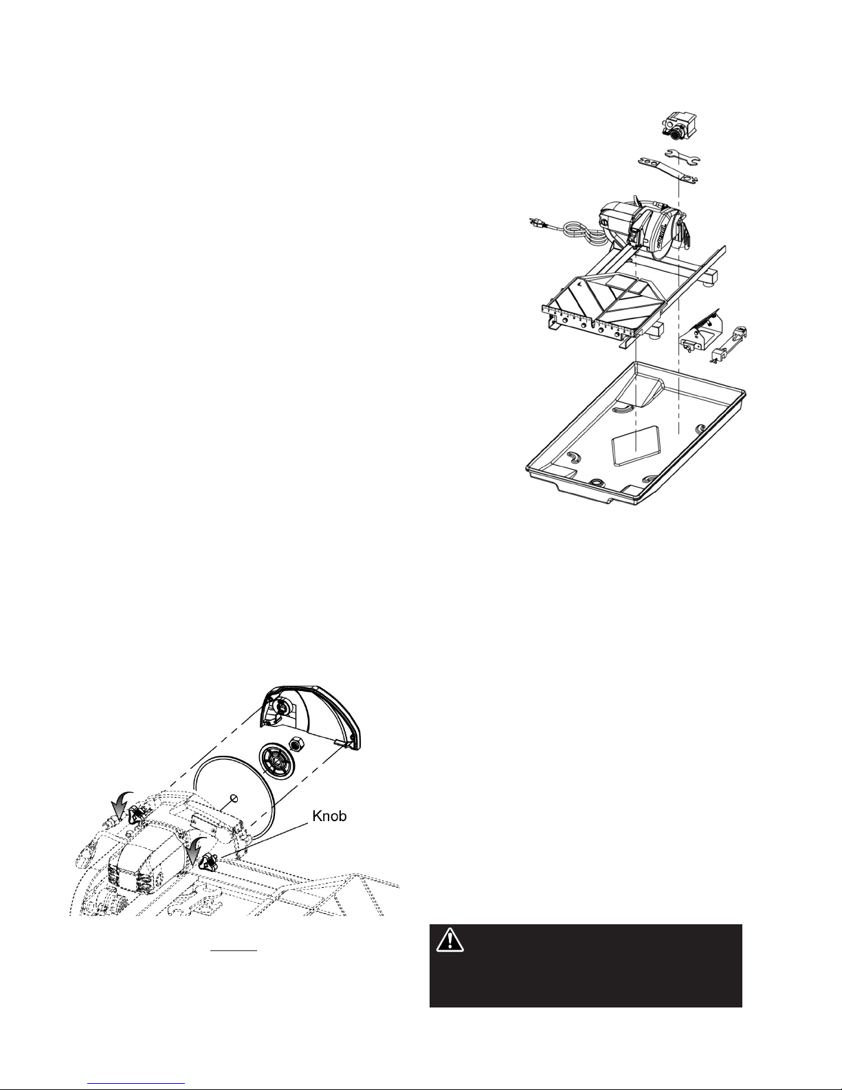
17. Make certain all adjusting knobs or locks are
tight and engaged in their detents and that
movable parts not intended to move during
operation are securely locked before making a
cut. Be careful not to over tighten.
18. Before connecting the machine to a power
source check to see that the “On/Off” switch is
in the “off” position.
• Make sure the blade is not contacting
anything before connecting to a power
source and starting the motor.
• Know how to stop the machine quickly in
case of an emergency.
19. rounding Instructions
• In the event of a malfunction or
breakdown, grounding provides a path of
least resistance for electric current to
reduce the risk of electric shock. This tool
is equipped with an electric cord having
an equipment-grounding conductor and a
grounding plug. The plug must be
plugged into a matching outlet that is
properly installed and grounded in
accordance with all local codes and
ordinances.
• Do not modify the plug provided - if it will
not fit the outlet, have the proper outlet
installed by a qualified electrician.
• Improper connection of the equipment-
grounding conductor can result in a risk
of electric shock.
• Check with a qualified electrician or
service personnel if the grounding
instructions are not completely
understood, or if in doubt as to whether
the tool is properly grounded.
• Use only 3 wire extension cords that have
3 prong grounding plugs and 3 pole
receptacles that accept the tool’s plug.
Repair or replace damaged or worn cord immediately.
This tool is intended for use on a circuit that has an outlet
that looks like the one illustrated in Figure 6. The tool has
a grounding plug that looks like the plug illustrated in
Figure 6(A). A temporary adapter, which looks like the
adapter illustrated in Figure 6(B) and 6(C), may be used
to connect this plug to a 2 pole receptacle as shown in
Figure 6(B) if a properly grounded outlet is not available.
The temporary adapter should be used only until a
properly grounded outlet can be installed by a qualified
electrician. The green-colored rigid ear, lug, and the like,
extending from the adapter must be connected to a
permanent ground such as a properly grounded outlet
box.
Note: USE OF A TEMPORARY ADAPTER IS NOT
PERMITTED IN CANADA.
Additionally, water pump requires the use of a round
Fault Circuit Interrupter. Therefore, when using the water
pump receptacle, this tool must be plugged into a
properly installed round Fault Circuit Interrupter outlet.
See Figure 6(D). If a round Fault Circuit Interrupter
outlet is not available, Pearl Abrasive Co. has it available
as an accessory item. A plug-in round Fault Circuit
Interrupter may be plugged into a properly installed and
grounded 3-pole outlet. Refer to Figure 6(E).
20. Position of the Tile Saw
• To avoid the possibility of the appliance
plug or receptacle getting wet, position
tile saw to one side of a wall mounted
NOTE - Use of a Te porary Adapter is not per itted
in Canada.

– 11 –
receptacle to prevent water from dripping
onto the receptacle or plug. The user
should arrange a “drip loop” in the cord
connecting the saw to a receptacle. The
“drip loop” is that part of the cord below
the level of the receptacle, or the
connector if an extension cord is used, to
prevent water traveling along the cord and
coming in contact with the receptacle. See
Figure 7.
• If the plug or receptacle does get wet,
Do not unplug the cord. Disconnect the
fuse or circuit breaker that supplies power
to the tool. Then unplug and examine for
presence of water in the receptacle.
21. Extension Cords
• Use only extension cords that are
intended for outdoor use. These extension
cords are identified by a marking
“Accept ble for use with outdoor
ppli nces; store indoors while not in
use.” Use only extension cords having an
electrical rating not less than the rating of
the product. Refer to ch rt on p ge 14.
Do not use damaged extension cords.
Examine extension cord before using and
replace if damaged. Do not abuse
extension cords and do not pull on any
cord to disconnect. Keep cord away from
heat and sharp edges. Always disconnect
the extension cord from the receptacle
efore disconnecting the saw from the
extension cord.
* round Fault Circuit Interrupter ( FCI)
protection should be provided on the
circuit(s) or outlet(s) to be used for the
tile saw. Receptacles are available having
built-in FCI protection and may be used
for this measure of safety.
(A) (B)
Figure 6
Grounding Methods
(C) (D) (E)
rounding pin
rounding pin
Cover of
grounded
outlet box
Metal
Screw
rounding
Means
(Lug)
To reduce the risk of electrocution, keep
all connections dry and off the ground.
Do not touch plug with wet hands.
TOOL
Figure 7
Drip Loop
Supporting
Surface
Power Cord
Drip Loop

– 12 –
ix. CARE AND MAINTENANCE
For your safety efore performing any maintenance on the saw turn off the power switch
and unplug the power cord.
WARNING!
GENERAL RULES
• Always clean the machine before performing any
maintenance/ repair.
• Before performing any cleaning/maintenance
/repair, the machine must be switched off with the
main power switch.
Steps to Follow When Cle ning:
• Please do not use aggressive cleaners (i.e.
containing solvents). Do not use high-pressure
water jets, aggressive detergents or solutions and
liquids with a temperature exceeding 86ºF! Use a
fluff-free cloth only.
• Use a cloth which may be lightly moistened only for
removing dust and dirt. Hard packed dirt can be
removed with a soft brush.
• For the sake of safety, no water/cleaning
liquid/vapor may penetrate into the electric motor,
connectors/plugs, switches, etc. Therefore cover
all apertures, holes in the housing, connectors or
plugs, etc. or seal them with adhesive tape!
• Use a soft, low-pressure water jet and a brush to
rinse dirt and incrustations away. Be particularly
careful when near hazardous parts of the machine
(e.g. switch, motor). Clean the motor and switches
only by wiping with a moist cloth.
• Do not “rinse” the bearings of the drive elements to
prevent them from running dry. The ball bearings
of the machine are permanently lubricated.
• After cleaning, remove all covers and adhesive
tape! All screws/nuts which you may have
loosened must be tightened again!
• After wet cleaning, try the machine on a power
outlet which is equipped with a power breaker (i.e.
fault current circuit breaker). If the fault current
circuit breaker cuts the power supply, the machine
must be inspected by an authorized dealer prior to
use!
CLEANING
After every use of the machine:
• Remove dirty water from container.
• Remove dirt and mud from the bottom of the
container.
• Rinse the immersion pump with fresh water to
prevent the water pump from clogging with
residual dirt.
After wet cle ning nd before using the m chine
g in:
• Connect the machine to an electric power outlet
equipped with a “ FCI” safety power breaker. If the
safety power breaker cuts off the electrical power
supply, do not try to operate the machine but have
it checked by an authorized dealer first.
PROLONGED PERIOD OF NON-USE
Before not using the m chine for prolonged period
of time:
• Clean and lubricate all movable parts. However, do
not grease the guide rails.
After not using the m chine for prolonged period of
time:
• Check that the stand is safely fixed.
• Check that all screw joints and nuts are fixed.
• Check that the cutting table is seated properly on
the guide rails and that it moves easily along the
entire length of the rails.
• With the saw blade removed, switch on the motor
for an instant and switch it off again. If the motor
does not run, have the machine inspected by a
qualified electrician.
• Check that the immersion pump works properly.
Turn on the cooling water tap and switch the
machine on. If the pump does not give any water or
only a little, switch the machine off at once. Clean
the pump, or replace if necessary.
EXTREME TEMPERATURE
Ambient temperature below 32° F (Winter):
• To prevent the water in the pump and cooling
system from freezing, remove the water after using
the machine or when there will be a long break.
Make sure that the cooling system is entirely
drained so that there is no water left inside the
pump and water hose!

– 13 –
WATER PUMP MAINTENANCE
When the m chine h s not been used for long period of
time, h rd p cked dirt m y begin to build up inside the pump
nd block the pump wheel. If the m chine is ctiv ted with
the immersion pump blocked, the electric motor of the pump
will be d m ged within few minutes! Ple se follow the
steps listed below to cle n the pump before oper ting the
s w:
1. Remove the immersion pump from the water container.
2. Clean the immersion pump.
3. Loosen the fixing screws of the pump lid.
4. Take the lid off the pump. Be careful not to damage or
lose the gasket underneath.
5. Clean the pump lid.
6. Remove all dirt and incrustations from the pump wheel.
7. Check whether the pump wheel can be easily turned.
8. Then reassemble the immersion pump correctly and
check whether it works properly.
CARBON BRUSH REPLACEMENT
1. Unplug the saw before proceeding any further.
2. Locate the carbon brush caps found on the left and right
side of the motor housing. Remove the caps (turn
counter- clockwise to unscrew) to allow the carbon
brushes to spring out. (See figure 8) If they do not come
out after the caps are removed, use a flat screw driver to
gently nudge them out.
3. When installing the new brushes, make sure they fit
snugly into the slots. Do not modify the replacement
brushes (i.e. file them down) or use non OEM brushes,
as it may damage the armature and in doing so voids the
manufacturer warranty.
4. Perform steps 1 through 3 in reverse to reinstall the fan
cover.
REALIGNMENT
Method 1:
This procedure de ls with the most common source of
mis lignment th t occurs when the guide r ils re not p r llel
with the bl de.
1. Set the cutting depth such that the blade passes through
the table, not over.
2. Place a straight edge (i.e. carpenter’s square) on the
cutting table as shown in figure 9.
3. Loosen the left and right guide rails by loosening the
fasteners found at the ends of the rail. (see figure 9) The
left rail should be slightly loose, so there is not too much
play during adjustments, but the right rail should move
freely as it will be adjusted last.
4. Make sure the short portion of the straight edge is placed
flush against the ruler guide. Adjust the left guide rail so
that the front and rear edges of the blade touch the straight
edge, although a tolerance of 0.1mm between the front
and rear edges is allowed. Perform this adjustment along
the entire length of the straight edge.
5. Position the table as close to the user as possible. Place
the straight edge flush against the ruler guide and blade.
Without holding onto the straight edge, gently move the
table towards the rear of the saw and then back. Observe
any gaps that may appear between the straight edge and
blade or between the straight edge and ruler guide. A gap
exceeding the allowed tolerance means that the table is
not moving parallel to the blade; hence, further
adjustments as outlined in step 4 will be required.
However, if scenario A or B described below occurs, other
adjustments may be required instead.
A. If the straight edge only touches the blade when the
table is positioned midway along the rail or at the
ends of the rail, then the rail may be deformed (i.e.
bowed). (see figure 10) Perform test cuts to
determine if the rail should be replaced. Typically a
bowing displacement of about 0.2mm will not affect
cutting accuracy.
B. If the straight edge touches both edges of the
blade initially, but shifts apart as the table travels
along the rail, proceed to method 2 below.
Figure 9
Figure 3Figure 8
Figure 10

– 14 –
x. ELETRICAL MOTOR SPECIFICATIONS
6. Tighten the fasteners at both ends of the left rail.
7. Adjust the right guide rail so that the horizontal rollers.
8. Tighten the fasteners at both ends of the right rail.
If alignment has been achieved do not proceed to method 2.
Method 2:
This procedure corrects nother source of mis lignment th t occurs
when the t ble’s orient tion is not p r llel with the guide r ils.
1. If the table shifts to the right as it travels away from the user, a
shim needs to be added to the guide roller furthest from the ruler
guide. On the other hand, if the table shifts to the left, a shim
needs to be added to the guide roller closest to the ruler guide.
Remove the appropriate guide roller to insert a shim between the
roller and table, then reattach. (See figure 11). On the severity of
the shift, more than one shim may be required.
2. After adding shim(s), mount the table onto the guide rails and
realign the table to the blade using method 1. Check to see if any
shifting persists. A shift tolerance of 0.2mm is allowed. A shift in
excess of that will require further adjustment—repeat step 1.
LEVELING ADJUSTMENT
This procedure levels the t ble so th t it is perpendicul r to the
bl de nd flush g inst the r ils.
1. Loosen the socket bolts on the flat roller plate so that the roller
can swing freely about the bolt. (See figure 12). Do this for both
flat roller plates.
2. Hold the table against the guide rails. The flat rollers should
reposition themselves to maintain contact with the guide rails. If
the table is not perpendicular to the blade, lift the right side of the
table instead to obtain the proper angle. A square tool will be
required to confirm the angle. Tighten the socket bolts. Check the
table for play. Repeat step 1-2 if some play is still present.
Figure 12
Horse ower 1 HP
Volts 115 V/ 60hz
Amps 8.5 amps
Motor R M 6,000 rpm
Cycle 60
hase 1
WIRE
GAUGE
No. 12
No. 10
No. 8
LENGTH OF CORD
25'
50'
75'
Recommendations:
• It is recommended that a 15 amp circuit be used while operating this
saw. This will prevent any loss of power or interruption.
• Always plug saw as close as possible to the power source while
operating. This will allow you to receive optimum electricity.
Electrical Wiring Diagram
WARNING: To avoid permanent
motor damage, you must use the
correct extension cord. Never use more
than one extension cord at a time.
Follow the chart for proper size.
Figure 11
Shim
Guide Roller

pa-7pRO FRaMe aSSeMBLY
1 Primary frame weldment PA171123
2 Left rail (758L) PA00068
3 Right rail (758L) PA00069
4 D37.5*d8*15L Rubber feet assembly (4) PA00090
5 Water plug assembly S1000-48
6 M8 x 1.25 Blind rivet nut PA171081
7 M8 x 1.25 x 20L Cross screw CX38081
8 M8 Narrow washer PA00016
9 M4 Narrow washer CX38044
10 M8 Spring Lock Washer PA00052
11 M8 x 1.25 x 20L Hex bolt PA00021
12 M4 x 1.59 x 10L cross tapping screw PA130037
PART NAME PART NUMBER
– 15 –
xi. REPLACEMENT PARTS LISTS
pa-7pRO CUTTiNg TaBLe aSSeMBLY
1 Cutting table assembly PA00072
2 Cutting fence PA00002
3 uide roller assembly (2) PA00004
4 M 8 x 1.25 Nut PA00015
5 Teflon flat roller assembly (2) PA00005
6 Type 3 Table lock Assembly PA171069
7 M8 x 1.25 x 20L Socket head hex screw PA00019
8 M8 Narrow washer PA00016
9 M8 Spring Lock Washer PA00052
10 M8 x 1.25 x 20L Hex bolt PA00021
11 D12.7 d8.5 X 6L Spacer PA00003
12 M8 x 1.25 x 40L Socket head hex screw PA00012
PART NAME PART NUMBER

– 16 –
1 Cutting table assembly PA00072
2 253 gal/hr Water pump CX38011
3 Frame assembly PA171122
4 PA7PRO Cutting head PA171143
5 SUS Water tray assembly PA00070
6 Wrench 17mm PA171079
7 PA7PRO Outer blade guard assembly PA171145
8 Outer flange PSV10031
9 Inner flange PSV10031
10 7in. blade DTL07HPXL
11 5╱8 - 11 UNC Nut PSV00004
12 M8 x 1.25 x 45L Hex Flange bolt PA171146
13 M8 Wide Washer PA00016
14 M8 Spring Lock Washer PA00052
15 M8 x 1.25 Nylon Nut PA0812502
16 M8 x 1.25 x 20L Flat point set screw PA25118
17 M8 x 1.25 x 40L Socket head hex screw PA00012
18 M6 X 1.0 X 30L Knob PA103790
19 M6 X 1.0 X 70L Knob PA171127
20 Water Hose (1ft) PSV00040
21 Y adapter (plastic) PA171147
22 Female 8D x 1/8" NPT straight fitting PA171148
PART NAME PART NUMBER PART NAME PART NUMBER
pa-7pRO MaiN aSSeMBLY

– 17 –
pa-7pRO CUTTiNg Head aSSeMBLY
1 Cover plate PA171091
2 M5 x 0.8 x 12L Cross screw PA141113
3 M5 x 0.8 x 16L Cross screw V3925058
4 M4 x 0.7 x 6L Cross screw PA103788
5 M4 Spring Lock Washer PA00039
6 M5 Spring Lock Washer V3925053
7 M4 x 0.7 x 8L Countersunk cross screw PA141127
8 ear cover PA00027
9 M5 Wide Washer V3925054
10 Motor replacement kit PA171094
10.1 Motor Housing Includes Field Windings PA171096
10.2 Armature with Inner & Outer Bearing PA171097
10.3 Baffle PA171098
11 D22 d8 Radial bearing 608 ZZ CX380055
12 D35 d15 Radial bearing 6202 ZZ V390035
13 M4 Narrow washer CX38044
14 M6 Narrow washer PA00082
15 Blade shaft PA171099
16 Blade shaft gear PA171100
17 M15 External C-clip PA00044
18 5 x 16 Woodruff key V390033.1
19 Carbon brush cap V390050
20 17mm X 7mm Carbon brush (2) V390051
21 Power switch plate PA171102
22 Rubber gasket CX38087
23 20A 125V/12A 250V On/Off switch CX38085
23A On/Off switch Lock Key PA171034.1
24 Multi directional quick attach fitting PA171088
25 Aluminum plate PA171103
26 M4 Standard rivet PA171104
27 Motor Retaining Plate PA171105
28 Rubber splash guard PSV100023
29 M6 x 1.0 x 12L Hex bolt PA061001207
30 D28 d20mm Oil seal PA00033
31 Water deflector PA171106
32 PA7Pro Cutting head casting assembly PA171107
PART NAME PART NUMBER PART NAME PART NUMBER
1 PA7PRO Outer blade guard assembly PA171145
2 Multi-directional water fitting PA171088
3 Water deflector PA171089
4 M4 x 0.7 x 6L Cross screw PA103788
PART NAME PART NUMBER
pa-7pRO BLade gUaRd aSSeMBLY
23A

– 18 –
xiii. ACCESSORIES & PARTS
Name (Qty.)
Stainless Steel Water Tray (1)
Drain plug not included
art Number
PA00072
Name (Qty.)
Drain Plug (1)
art Number
S1000-48 Name (Qty.)
Optional Universal
Saw Stand (1)
art Number
V35010-UV
Name (Qty.)
Optional Complete
Miter Block with
Knob (1)
art Number
S1000-34
Knob Only (1)
V35016
Knob Only (1)
V35016
xii. TROUBLESHOOTING
For your safety and the safety of others, turn the power switch off and always remove the plug from
power source efore trou leshooting. Repairs performed y unauthorized personnel could cause serious hazard. We
recommend that service to this tool e performed y a qualified service technician with original equipment replacement parts.
WARNING!
EXCESSIVE NOISE. Possible blade shaft bearing wear,
motor belt loose or motor fan rubbing on housing. Have
tool serviced.
BLADE WILL NOT CUT. Check for worn out diamond edge.
Be sure that the arrow on the blade is rotating the same
direction as the motor arbor and/or arrow on the blade
guard. Make sure the blade is suitable for the material to be
cut. If blade has been used to cut a material that is hard, it
may have become dull, dress the blade by cutting a light
weight abrasive building block to expose fresh diamonds.
Blade dressing stones are available from your local Pearl
Warehouse.
MOTOR WILL NOT START. Check power supply. If the
water pump turns on when the power switch is in the “on”
position, but the motor does not, have the motor serviced.
MOTOR WILL NOT STO . The contacts in the switch may
have become arched together in the on position, have it
serviced.
MOTOR SHUTS OFF DURING O ERATION. Check to see
that the circuit you are using is not overloaded with lights
or other equipment. The fuse or circuit breaker may not
have sufficient capacity, use 20-amp power. If you are
using an extension cord check the extension cord table to
be sure it is heavy enough to carry the current this product
will draw. See P ge 14 for electric cord reference.
EXCESSIVE VIBRATION Check to see that the blade is
mounted properly according to safe operating practices
section. Blade may be out of balance, try a different blade.
Arbor shaft bearings possibly worn, have tool serviced.
NOT CUTTING SQUARE. Check the main table and carriage
adjustment as well as the blade alignment procedure
located in the care and maintenance section.
MAIN TABLE DOES NOT MOVE FREELY. Inspect the guide
rails and rollers for build up of tile chips or dry slurry
deposits. Clean and check guide roll or adjustments,
according to the procedure in the care and maintenance
section.
NO WATER FLOW TO BLADE. Check the water feed tube for
kinks or obstructions. Check the inlet screen to ensure it is
not clogged. Remove the pump inlet and turn the impeller
to ensure it is not damaged or jammed. Clean the impeller
if necessary and apply a drop of light oil to the shaft - be
sure the impeller spins freely.
OOR MACHINE ERFORMANCE WITH LITTLE OWER.
Check cord/extension cable for appropriate length and gage.
Check power network for sufficient power and circuit
breaker capacity.
CENTER HOLE IN BLADE OVERSIZE OR WORN. Saw blade
has slipped on shaft while running. Check shaft for damage
and replace blade.
Name (Qty.)
Complete 45˚/90˚
Rip uide with
Knob (1)
Name (Qty.)
Complete 45˚/90˚
Rip uide with
Knob (1)
art Number
V35000

– 19 –
xv. HOW TO ORDER PARTS
Please have the following information ready before calling:
• Serial Number of your Tile Saw
• Model Number of the Tile Saw
• When purchased and where
• Part Description
All parts listed may be ordered from your Local warehouses. If the part is not stocked locally, call our Corporate office
and ask for our Customer Service Department. For Technical Support call 1-800-969-5561. In Canada call 1-800-387-
0008. There is a $25.00 minimum order.
Return Policy: Return goods for credit or exchange on the basis of the following terms: (1) They must be current
products; (2) Items returned for replacement or refund should be in original cartons and must be accompanied by a
packing slip with the following information: Returned oods Authorization (R A) number obtainable from Customer
Service Department • List of items returned • Reason(s) for return(s) • Copy of original invoice(s); (3) Freight charges
must be assumed by sender; (4) Returning goods are subject to a 15% handling charge to cover our cost of repacking
and restocking. All Prices are subject to change without notice.
Disclaimer: Pearl Abrasive Co. reserves the right to make changes or improvements on its products without incurring
an additional obligation including any obligation to make corresponding changes or improvements to products
previously manufactured or sold. Pearl reserves the right to discontinue products at any time without notice.
All illustrations displayed in this manual are the property of Pearl Abrasive Co. and shall not be duplicated or
reproduced without the express written consent of Pearl Abrasive Co.
xiv. THE RIGHT BLADE DOES THE RIGHT JOB
For the most effective cutting and blade life always use the recommended Pearl Abrasive Co. blade.
APPLICATION
PEARL
BLADE
SERIES
Reactor ADM
H XL Series
H Series
Turbo Mesh
DTLB19 Series
ro-V Series
Glass Blade
SH Series
CERAMIC EXTRA HARD ORCELAIN MARBLE GRANITE HARDSTONE GLASS TILE MOSAIC
TILE CERAMIC METAL TILES

art No. A7 ROMAN • 01/16
GEORGIA • USA
3950 STEVE REYNOLDS BLVD.,
NORCROSS, EOR IA 30093
ONTARIO • CANADA
375-2 PIDO ROAD
PETERBOROU H, ONTARIO K9J-6X7
COR ORATE OFFICE: SO. CALIFORNIA • USA
6832 E. SLAUSON AVENUE, COMMERCE, CA 90040-0031
562-927-5561 • FAX 562-928-3857
Toll Free: 800-969-5561
www.pearlabrasive.com
Table of contents
Other Pearl Abrasive Saw manuals

Pearl Abrasive
Pearl Abrasive VX141MSPROR Owner's manual

Pearl Abrasive
Pearl Abrasive VX10RS User manual

Pearl Abrasive
Pearl Abrasive PA-10 Owner's manual

Pearl Abrasive
Pearl Abrasive PA20HSP Owner's manual

Pearl Abrasive
Pearl Abrasive VX7.2XL Owner's manual

Pearl Abrasive
Pearl Abrasive X10RS Owner's manual

Pearl Abrasive
Pearl Abrasive VX MSPRO VX141MSPRO Owner's manual

Pearl Abrasive
Pearl Abrasive VX10.2XLPRO User manual