4
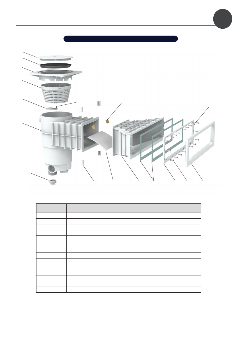
VERSION PANNEAULINER
N° REF DÉSIGNATION QUANTITÉ
1 80176 COUVERCLE NEUTRE 1
2 60360 COUVERCLE PERDU 1
4 62513 TÉLESCOPE SKIMMERSKIMFILTRE 1
5 60284 OBTURATEUR DE FOND SKIMMER 1
7 60392 BOITIER MONOBLOC 1
8 64130 PINCES MEURTRIÈRE 4
9 62341 BARRIÈRE POUR SKIMMER 1
10 80493 JOINT A500 2
11 80491 CONTRE BRIDE A500 1
12 80492 CACHE VIS A500 1
13 62461 ARRÊT BARRIÈRE 2
14 80490 MEURTRIÈRE A500 DESIGN PANNEAU 1
15a 62419 RONDELLE INOX M5 11
15b 62420 ECROU INOX M5 11
15c 62418 VIS TF M5X20 11
15d 60469 VIS TF 5.5X25 13
15e 62423 VIS TF 3.9X25 9
1
2
3
4
5
6
7
8 9 15a 15b 15c 15d
15d 15e
10 11 12
1413
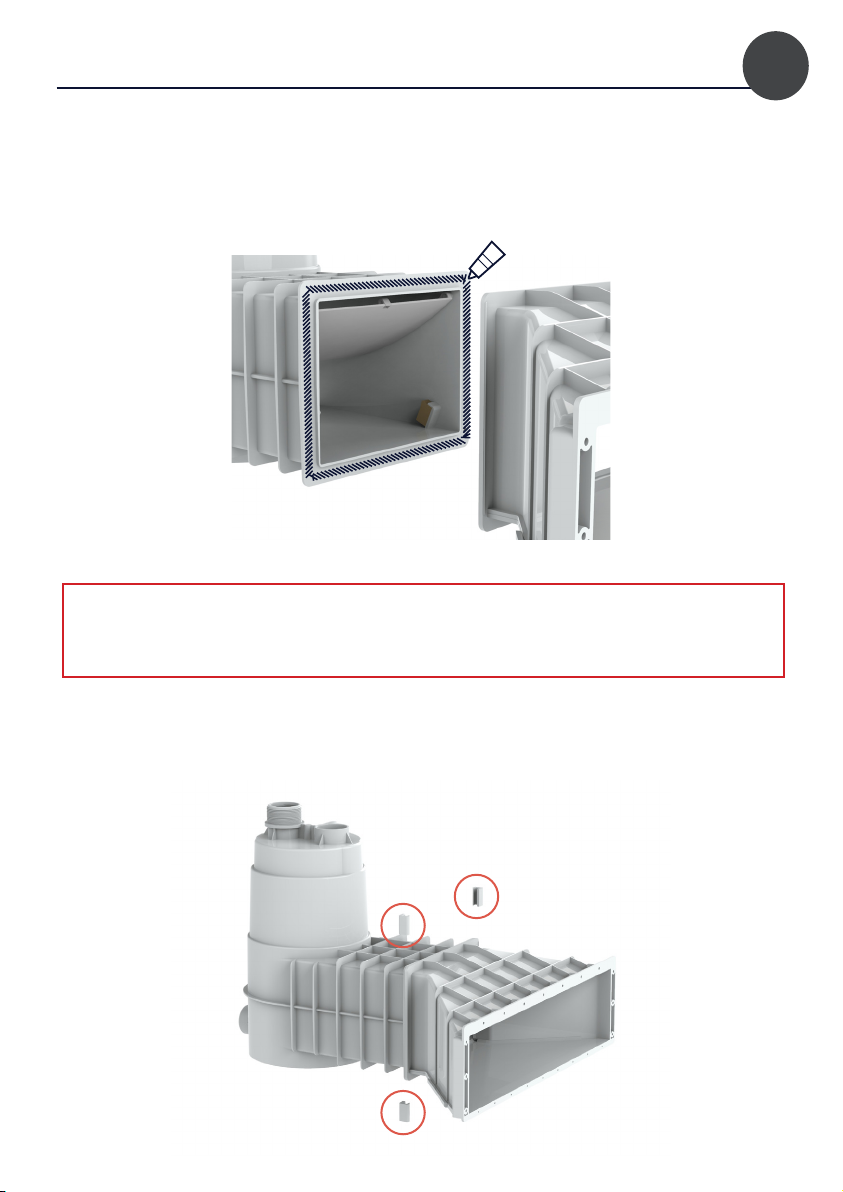
2. composition des kits