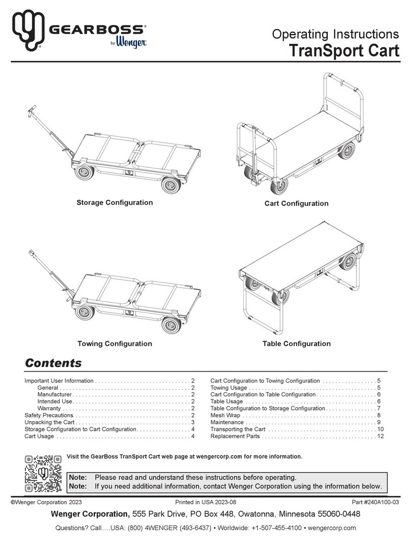
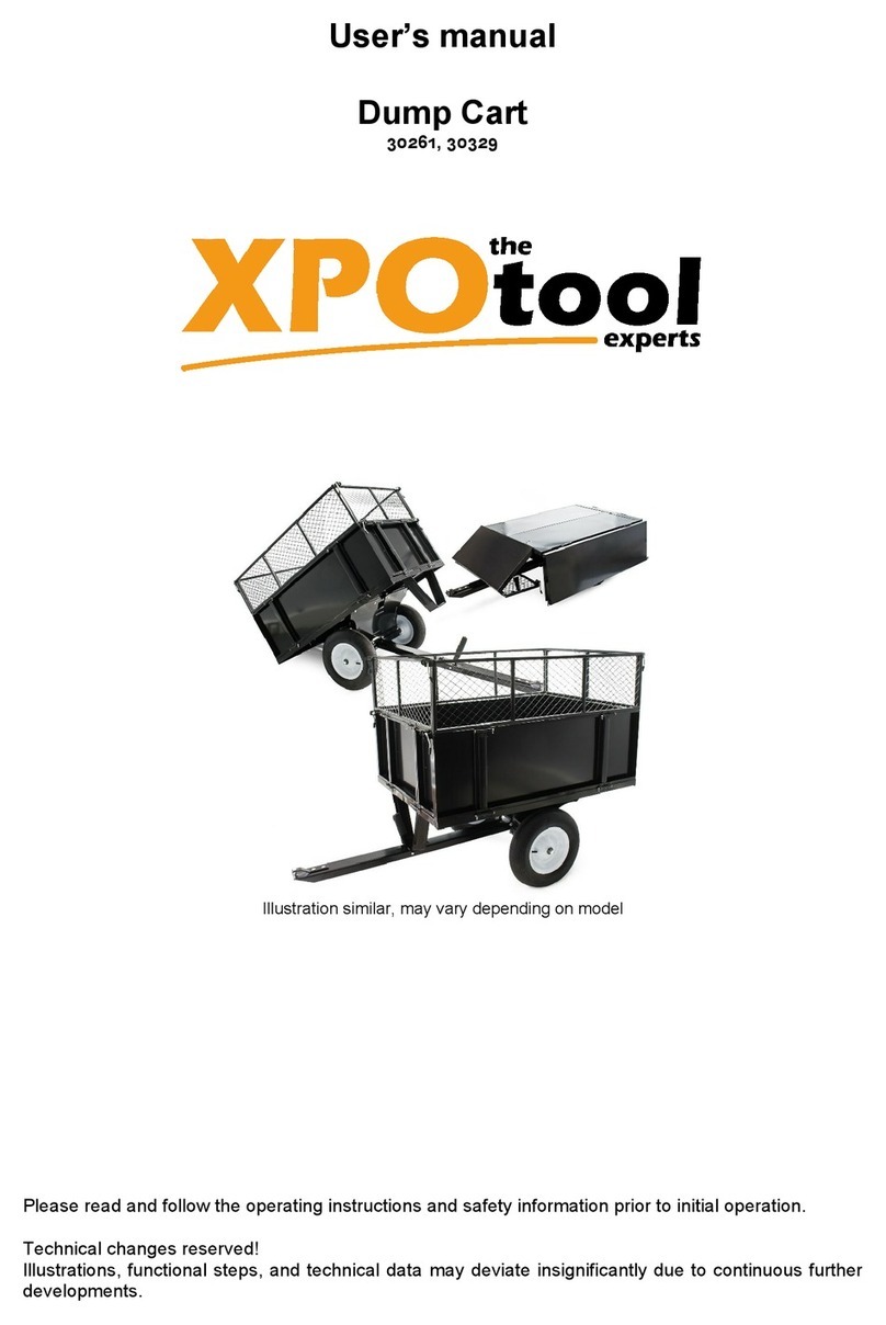
Wenger OnBoard Percussion Cart User manual

Assembly and Owner’s Manual
OnBoard®Percussion Cart
CONTENTS
©Wenger Corporation 2016 Printed in USA 01/16 Part #210C291-02
Wenger Corporation, 555 Park Drive, P.O. Box 448, Owatonna, Minnesota 55060-0448
Questions? Call.....USA: (800) 4WENGER (493-6437) • Worldwide: +1(507) 455-4100 • www.wengercorp.com
Note: Please read and understand these instructions before assembly or use.
Note: Remove all items from the shipping cartons and arrange them in a convenient location.
Refer to the illustrations on the following pages. If you need additional information,
contact the Wenger Corporation using the information below.
Important User Information . . . . . . . . . . . . . . . . . . . . . . . . . . . . . . . . . . . . . . . . . . . . . . . . . . . . . . . . . . . . . . . . . . .2
Safety . . . . . . . . . . . . . . . . . . . . . . . . . . . . . . . . . . . . . . . . . . . . . . . . . . . . . . . . . . . . . . . . . . . . . . . . . . . . . . . . . . .3
Tools Required . . . . . . . . . . . . . . . . . . . . . . . . . . . . . . . . . . . . . . . . . . . . . . . . . . . . . . . . . . . . . . . . . . . . . . . . . . . . .4
Fastener List . . . . . . . . . . . . . . . . . . . . . . . . . . . . . . . . . . . . . . . . . . . . . . . . . . . . . . . . . . . . . . . . . . . . . . . . . . . . . .4
Parts List . . . . . . . . . . . . . . . . . . . . . . . . . . . . . . . . . . . . . . . . . . . . . . . . . . . . . . . . . . . . . . . . . . . . . . . . . . . . . . . . .5
Assembly . . . . . . . . . . . . . . . . . . . . . . . . . . . . . . . . . . . . . . . . . . . . . . . . . . . . . . . . . . . . . . . . . . . . . . . . . . . . . . . . .6
Operation . . . . . . . . . . . . . . . . . . . . . . . . . . . . . . . . . . . . . . . . . . . . . . . . . . . . . . . . . . . . . . . . . . . . . . . . . . . . . . . .9
Storage . . . . . . . . . . . . . . . . . . . . . . . . . . . . . . . . . . . . . . . . . . . . . . . . . . . . . . . . . . . . . . . . . . . . . . . . . . . . . . . . . .11
Maintenance . . . . . . . . . . . . . . . . . . . . . . . . . . . . . . . . . . . . . . . . . . . . . . . . . . . . . . . . . . . . . . . . . . . . . . . . . . . . . .11
Replacement Parts List . . . . . . . . . . . . . . . . . . . . . . . . . . . . . . . . . . . . . . . . . . . . . . . . . . . . . . . . . . . . . . . . . . . . .12

2
IMPORTANT USER INFORMATION
GENERAL
Copyright © 2016 by Wenger Corporation
All rights reserved. No part of the contents of this manual may be reproduced, copied, or transmitted in
any form or by any means including graphic, electronic, or mechanical methods or photocopying,
recording, or information storage and retrieval systems without the written permission of the publisher,
unless it is for the purchaser's personal use.
Printed and bound in the United States of America.
The information in this manual is subject to change without notice and does not represent a commitment
on the part of Wenger Corporation. Wenger Corporation does not assume any responsibility for any
errors that may appear in this manual.
In no event will Wenger Corporation be liable for technical or editorial omissions made herein, nor for
direct, indirect, special, incidental, or consequential damages resulting from the use or defect of this
manual.
The information in this document is not intended to cover all possible conditions and situations that might
occur. The end user must exercise caution and common sense when assembling or installing Wenger
Corporation products. If any questions or problems arise, call Wenger Corporation at 1-800-733-0393.
MANUFACTURER
The OnBoard®Percussion Cart is manufactured by:
Wenger Corporation
555 Park Drive
Owatonna, MN 55060
1-507-455-4100 • 1-800-733-0393
www.wengercorp.com
INTENDED USE
•This product is intended for indoor use in normal ambient temperature and humidity conditions — it
must not be exposed to prolonged outside weather conditions.
•This product is intended to be assembled only as described in these instructions.
WARRANTY
This product is guaranteed free of defects in materials and workmanship for five full years from date
of shipment. A full warranty statement is available upon request.

3
SAFETY PRECAUTIONS
Throughout this manual you will find CAUTIONS and WARNINGS. They are defined as follows:
• WARNING; failure to follow the instruction may result in serious injury or death.
• CAUTION; failure to follow the instruction may result in serious injury or damage to property.
Note: Failure to comply with precautions in this section can result in serious injury.
ASSEMBLY
•Ensure anyone who helps assemble the Percussion Cart has read and understands this manual.
OPERATION
•Percussion Cart maximum total load capacity is 150 lbs uniformly distributed on the main support
bar.
•Each instrument support is limited to a maximum load of 20 lbs if used in the vertical position and
10 lbs in the horizontal position.
•Instruments or accessories mounted on the 3/4” diameter instrument support bar must be secure
and positioned so the cart is stable and there are no dangerous protruding edges or surfaces.
•When the Percussion Cart is left unattended, it must be placed in a secure position so that it
doesn’t move or roll into vehicles, structures or people.
•All four casters must be in contact with the floor or ground at all times.
•Always distribute the weight evenly on the cart. Avoid top-heavy loading.
•Avoid ramps with a rise or drop steeper than a 1-foot in a 12-foot horizontal distance.
•Always move slowly up or down a ramp with the narrow end of the cart in the direction of travel.
•Do not pull or push too high on the cart or pull or push on the sides of the cart which may cause
the cart to tip over.
•Avoid off-center loads which may cause the cart to tip over.
•Because swivel casters move in any direction, the operator must move the cart slowly and have a
clear view to avoid obstructions and individuals standing in the direction of travel.
•If the Percussion Cart is heavily loaded, two people are always required to move the cart (one
pushing at the rear and one guiding at the front).
•When transporting this product in a vehicle, it must be braced with tie-downs, chains or cargo
straps designed specifically to prevent the cart from moving.
•Blankets or other padding material may be required to avoid damage to the cart and accessories
from vibration and impact during transport.
•When moving the cart do not ride on the cart and do not allow others to ride on the cart.
•Use caution when removing objects from the cart or when placing objects on the cart.
•When towing the Percussion Cart, avoid tight turns which may result in the tow vehicle making
contact with the cart or tow bar. Injury or damage may result.
Do not transport people or
stand on the Percussion
Cart.
!CAUTION
When towing the Percussion
Cart do not exceed 5 mph or
tow more than three carts
together.
!CAUTION
When towing the Percussion
Cart, avoid tight turns which
may result in the tow vehicle
making contact with the cart
or tow bar.
!CAUTION
4
TOOLS REQUIRED
FASTENER LIST
•9/16" Wrench or 9/16" Socket with Ratchet
•1/2" Wrench or 1/2" Socket with Ratchet
•3/16" Allen Wrench (provided)
Note: Extra hardware can be discarded.
Socket Screw, 5/16-18 x 3
Lock Nut, 3/8-16
Carriage Bolt, 3/8-16 x 1 Nylon Lock Nut,
5/16-18
10 11 12 13

PARTS LIST
Item # Description Item # Description
1 BASE ASSEMBLY 6 MOUNT ASSEMBLY
2 SWIVEL CASTER 7 SUPPORT WELDMENT
3 RIGID CASTER 8 TUBE CLAMP EXTRUSION
4 TOW BAR 9 ACCESSORIES CLAMP EXTRUSION
5 CURVED TUBE EXTRUSION
1
7
2
34
8
5
6
5
9

6
ASSEMBLE CASTERS (#2 AND #3) TO THE BASE ASSEMBLY (#1)
1. Align the swivel casters (#2) with the bolt holes on the base assembly (#1).
2. Assemble the casters to the base assembly (#1) using two 3/8-16 x 1
carriage bolts (#10) and lock nuts (#11). (Detail A)
Note: The same caster type (swivel or rigid) must be assembled to
each base assemblies.
3. Align the rigid casters (#3) with the bolt holes on the remaining
base assembly (#1).
4. Repeat step 2.
ASSEMBLE THE SUPPORT (#7) TO THE BASE ASSEMBLIES (#1)
5. Lay the base assemblies on end.
6. Align the cross member (#7) to the bolt holes located on inside the base assemblies. (Detail B)
7. Secure the support to the base assemblies using carriage bolt, 3/8-16 x 1 (#10) and 3/8" lock nuts
(#11).
ASSEMBLY
Detail A
Detail B
10
2
7
1
1
11
11
10

7
ASSEMBLY (CONTINUED)
Note: Make sure the Percussion Cart is secure and doesn’t roll away while assembling the
curved tube extrusion (#5)
ASSEMBLE THE CUR ED TUBE EXTRUSION (#5) ONTO THE PERCUSSION CART BASE.
8. Place the curved tube extrusion onto the clamps located at the top of the base assemblies (#1). Be
sure to center the curved tube extrusion so it is evenly positioned on the base units. (Detail C)
9. Place the accessory clamp extrusion (#9) parallel to the clamp located on the base assembly.
10. Using socket screw, 5/16-18 x 3 (#12) and nylon lock nut, 5/16-18 (#13), tighten the tube clamp
extrusions together securing the curved tube extrusion.
12
9
1
13
Detail C
5

8
ASSEMBLY (CONTINUED)
ATTACHMENT OF PERCUSSION MOUNT ASSEMBLY
The percussion mount assembly may be attached in the up, down, front or back position to receive
universal instrument mounts. Determine the direction in which the instruments are to be located on the
Percussion Cart. To attach the percussion mount assembly; (Detail D)
11. Place the percussion mount assembly (#6) and tube clamp extrusion (#8) parallel to each other, at
the desired location, on the curved tube extrusion (#5).
12. Insert the socket screw, 5/16-18x3 (#12) into the percussion mount assembly (#6) and through the
tube clamp extrusion (#8).
13. Using the lock nut, 5/16-18 (#13) tighten the percussion mount assembly (#6) onto the curved tube
extrusion (#5) uniformly. Do not over-tighten.
6
12
8
13
Detail D
5

9
LOADING THE PERCUSSION CART
1. Always distribute loads evenly.
2. Avoid off-center loads.
MO ING THE PERCUSSION CART
1. When the cart is left unattended, it must be placed in a secure position to avoid moving or rolling
into vehicles, structures or people.
2. When pulling or pushing the Percussion Cart, always pull or push at about waist level or lower.
Pushing above the main support bar can tip the Percussion Cart over. (Detail A)
3. If the Percussion Cart is heavily loaded, two people should always work together to move
the cart in the direction of travel that the rigid casters can move freely. One person pushing at
the rear and one person guiding at the front. Take care to avoid stationary objects or people
standing in the path of the Percussion Cart.
OPERATION
Detail A
Do not transport people or
stand on the Percussion
Cart.
!CAUTION

10
OPERATION (CONTINUED)
4. A separate tow bar (#4) is provided that inserts into two holes in the percussion cart base (#1).
The tow bar (#4) may also be used as a handle to pull the Percussion Cart manually or can be
attached horizontally to a lawn and garden tractor. (Detail B)
5. When the tow bar is removed, store it out of the way so that it is not an obstruction or hazard.
6. If the Percussion Cart is transported in a vehicle, it must be braced or strapped to the vehicle so
that it cannot move. Bracing must use tie-downs or straps specifically designed to prevent the
Percussion Cart from moving in the vehicle. Remove objects or instruments that may be damaged
during transport. Secure Percussion Cart at the lower frame. Pads or other protection against
abrasion may be required.
1
4
Detail B
When towing the Percussion
Cart do not exceed 5 mph or
tow more than three carts
together.
!CAUTION
When towing the Percussion
Cart, avoid tight turns which
may result in the tow vehicle
making contact with the cart
or tow bar.
!CAUTION
11
STORAGE
When leaving the Percussion Cart in a stationary position or in storage, block or secure casters to
prevent the cart from moving and possibly causing damage.
MAINTENANCE
1. Clean the Percussion Cart with a mild detergent and warm water. Avoid using harsh or abrasive
cleaning products.
2. Immediately replace any caster wheels that do not rotate or turn freely.
3. Immediately replace or repair any tire that develops a flat area.
4. Recommended tire pressure is 50 psi. Do not exceed the maximum tire pressure shown on the
sidewall of the tire.
5. During heavy usage, periodically check and tighten item #4 for the clamp extrusions holding the
curved extrusion.
6. Check all fasteners to be certain they are secure before use.
7. Grease zerks and bushings if required.

12
REPLACEMENT PART LIST
12
21
18
9
21
13
10
1
3
11
13
12
8
6
7
5
14
15 16
10
1
17
2
11
20
19
4
Item # Description Item # Description
1 PERCUSSION CART BASE ASSEMBLY 12 SOCKET SCREW, 5/16-18x3
2 SWIVEL CASTER, 9" DIAMETER 13 LOCK NUT, 5/16-18
3 RIGID CASTER 9" DIAMETER 14 SELF TAP SCREW, 1/4-20x3/4, TORX
4 TOW BAR 15 EXTRUSION CAP
5 CURVED TUBE EXTRUSION 16 UPRIG T EXTRUSION
6 PERCUSSION MOUNT ASSEMBLY 17 WENGER ONBOARD DECAL
7 PERCUSSION CART SUPPORT 18 PLUG, 2.00, BLACK
8 TUBE CLAMP EXTRUSION 19 LOCK WAS ER, 1/4"
9 SOCKET SCREW, 1/2-13x1 20 SELF TAP SCREW, 1/4-20x1 1/4
10 CARRIAGE BOLT, 3/8-16x1 21 ACCESSORY CLAMP EXTRUSION
11 LOCK NUT, 3/8-16
8
Table of contents
Other Wenger Outdoor Cart manuals

Wenger
Wenger Roll-A-Deck Kit User manual

Wenger
Wenger OnBoard Uniform User manual

Wenger
Wenger teacherTAXI User manual

Wenger
Wenger Tourmaster Storage Cart User manual

Wenger
Wenger Gearboss User manual

Wenger
Wenger Tourmaster Storage Cart User manual

Wenger
Wenger OnBoard Timpani Cart User manual

Wenger
Wenger OnBoard 210A327-02 User manual

Wenger
Wenger GEARBOSS TranSport Cart User manual

Wenger
Wenger teacherTAXI Assembly instructions