manuals.online logo
Brands
  1. Home
  2. •
  3. Brands
  4. •
  5. Wenglor
  6. •
  7. Accessories
  8. •
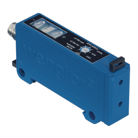
  9. Wenglor OPT2015 User manual

Wenglor OPT2015 User manual

wenglor sensoric gmbh
wenglor Straße 3
88069 Tettnang
(+49 (0)7542 5399-0
info@wenglor.com
Weitere wenglor Kontakte finden Sie unter:
For further wenglor contacts go to:
Autres contacts wenglor sous :
www.wenglor.com
DE
DE FREN
514
Änderungen vorbehalten
Right of modifications reserved
Modifications réservées
24.06.2013
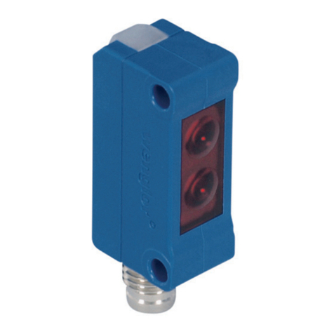
1 = Sendediode/Transmitter diode/ Diode émettrice
2 = Empfangsdiode/Receiver diode/ Diode réceptrice
SAP NR. 87258
QUICKSTART
OPT2015
EG-Konformitätserklärung
Die Bauart der Produkte wurde in Übereinstimmung mit der Richtlinie 2004/108/EG entwickelt, konstru-
iert und gefertigt. Folgende internationale Normen und Spezifikationen finden Anwendung:
•EN 60947-5-2:2007 Niederspannungsschaltgeräte, Teil 5-2: Steuergeräte und Schaltelemente –
Näherungsschalter
•EN 60825-1:2007 Sicherheit von Lasereinrichtungen
Prüfschärfegrad III nach IEC 61000-4-4:2004 + C1:2006 + C2:2007 + A1:2010 in Verbindung mit Z0033.
Weitere für die Anwendung gültige Normen sind zu berücksichtigen.
EC Declaration of Conformity
The products are developed, constructed and manufactured according to the directive 2004/108/EC.
The following international standards and specifications apply:
•EN 60947-5-2:2007 Low-voltage switchgear and controlgear, Part 5-2: Control circuit devices
and switching elements – Proximity switches
•EN 60825-1:2007 Safety of Laser devices
Inspection level III according to IEC 61000-4-4:2004 + C1:2006 + C2:2007 + A1:2010 in combination with
Z0033. Any additional standards which are applicable for the given application must be observed.
CE Déclaration de conformité
Les produits sont développés, conçus et fabriqués selon la directive 2004/108/CE.
Les normes et prescriptions appliquées sont :
•EN 60947-5-2:2007 Appareillage à basse tension, Partie 5-2 : Appareils et éléments de
commutation pour circuits de commande – Détecteurs de proximité
•EN 60825-1:2007 Sécurité des appareils à laser
Niveau de sévérité d’essais III selon EC 61000-4-4:2004 + C1:2006 + C2:2007 + A1:2010 en relation
avec le Z0033. D’autres normes suivant les applications sont à prendre en compte.
Anschlussbild
Connection Diagram
Schéma de raccordement
Bedienfeld
Control Panel
Panneau
+ Versorgungsspannung „+“
Supply Voltage “+”
Tension d’alimentation «+»
– Versorgungsspannung „0 V“
Supply Voltage “0 V”
Tension d’alimentation «0 V»
La Sendelicht abschaltbar
Emitted light can be switched off
Lumière émettrice désactivable
O Analogausgang
Analog output
Sortie analogique
O– Bezugsmasse/Analogausgang
Ground for the analog output
Masse de référence pour sortie
analogique
E/A3 Eingang/Ausgang programmierbar
Input/Output programmable
Entrée / Sortie programmable
A1/2 Schaltausgang Schließer (NO)
Switching Output (NO)
Sortie de commutation Fermeture (NO)
Bestimmungsgemäße Verwendung
Dieses wenglor Produkt ist gemäß dem folgenden Funktions-
prinzip zu verwenden:
High-Performance-Distanzsensor
Diese Sensoren ermitteln den Abstand zwischen Sensor und
Objekt. Sie arbeiteten nach dem Prinzip der Lichtlaufzeitmes-
sung. Mit einem passenden Reflektor am Objekt ist eine sehr
genaue Positionsbestimmung auch in großer Distanz möglich.
Sicherheitshinweise
•Diese Anleitung ist Teil des Produkts und während der ge-
samten Lebensdauer des Produkts aufzubewahren
•Bedienungsanleitung vor Gebrauch des Produkts sorgfältig
durchlesen
•Montage, Inbetriebnahme und Wartung des vorliegenden
Produkts sind ausschließlich durch fachkundiges Personal
auszuführen
•Eingriffe und Veränderungen am Produkt sind nicht zulässig
•Produkt bei Inbetriebnahme vor Verunreinigung schützen
•Kein Sicherheitsbauteil gemäß EU-Maschinenrichtlinie
Laser-/LED-Warnhinweise
LASER CLASS 1
EN60825-1
2007
Laser Klasse 1 (EN 60825-1)
Normen und Sicherheitsvorschriften sind
zu beachten.
Technische Daten
Arbeitsbereich 0,2...100,2 m
Arbeitsbereich analog 0,2...100,2 m
Messbereich 100 m
Bezugsreflektor/Reflexfolie 4×OPT2030
Auflösung 4…20 mm
Linearität 0,05 %
Schalthysterese 13…50 mm
Temperaturdrift 0,5 mm/k
Lichtart Laser (rot)
Laser Klasse 1
Versorgungsspannung 18…30 V DC
Stromaufnahme (Ub=24 V) <100 mA
Schaltfrequenz 50 Hz
Messrate 1...100 /s
Ansprechzeit 10...200 ms
Temperaturbereich –25…60 °C
Spannungsabfall Schaltausgang <2,5 V
Schaltstrom Schaltausgang 200 mA
kurzschlussfest ja
verpolungs- und überlastsicher ja
Schutzklasse III
Schutzart IP68
Anschlussart M12×1, 8-polig
Ausgangsfunktion Fehlerausgang
PNP/NPN/Gegentakt
programmierbar
Analogausgang
Reflektortyp Montageabstand
OPT2030 5...100 m*
0,2...10 m
* bei Verwendung von 4 Reflektoren
Damit der Sensor ordnungsgemäß arbeitet, muss die Reflektorfläche
so gewählt werden, dass der gesamte Lichtfleck auf den Reflektor trifft.
Montagehinweise
Bei der Montage und dem Betrieb des Sensors sind die ent-
sprechenden elektrischen sowie mechanischen Vorschriften,
Normen und Sicherheitsregeln zu beachten. Der Sensor muss
vor mechanischen Einwirkungen geschützt werden. Das Gerät
ist so zu befestigen, dass sich die Einbaulage nicht verändern
kann. Zur Montage des Sensors wird ein wenglor Befesti-
gungssystem empfohlen. Zusätzlich muss ein passender Re-
flektor bzw. Reflexfolie montiert werden.
Inbetriebnahme
Sensor an die Spannungsversorgung (18…30 V DC) anschlie-
ßen. Es erscheint die Anzeigeansicht. Nach 2 Sekunden ist der
Sensor betriebsbereit. Die folgende Tabelle gibt eine Übersicht
über die typischen zusätzlichen Abweichungen innerhalb der
Warmlaufphase:
Zeit in min 0 1 2 5 10 15
Einschaltdrift in mm ±10 ±7 ±6 ±2 ±1 0
Navigation durch Tastendruck:
: Navigation nach oben.
: Navigation nach unten.
: Auswahl des markierten Menüpunkts
(Pfeil zeigt in Richtung Display).
: Übernahme der getroffenen Einstellung, Verlassen des
Menüs (Pfeil zeigt weg vom Display).
Durch Druck auf eine beliebige Taste ins Konfigurationsmenü
wechseln.
Hinweis: Wird im Konfigurationsmenü für die Dauer von 30 s
keine Einstellung vorgenommen, springt der Sensor automa-
tisch in die Anzeigeansicht zurück.
Durch erneuten Tastendruck springt der Sensor wieder in die
zuletzt verwendete Menüansicht. Wird eine Einstellung vorge-
nommen, wird diese beim Verlassen des Konfigurationsmenüs
übernommen.
Wichtig: Um eine Beschädigung der Tasten zu vermeiden,
bitte keine spitzen Gegenstände zur Einstellung verwenden.
Funktionsbeschreibung
Pin Funktion
Der Menüpunkt Pin Funktion dient dazu, die Funktion der Pins
einzustellen. Die Pins können jeweils unterschiedliche Funkti-
onen annehmen wie z. B. Schaltausgang, Fehlerausgang oder
Analogausgang. Als Eingang kann z. B. Laserabschaltung
oder externes Teachen eingestellt werden.
Eingänge/Ausgänge einlernen
In den weiteren Menüpunkten können die Ein- oder Ausgänge
genauer eingestellt werden, z. B. Teach-In eines Schaltaus-
ganges.
Der Sensor besitzt zahlreiche weitere Funktionen. Erklärungen
hierzu finden Sie in der ausführlichen PDF-Bedienungsanlei-
tung.
Wartungshinweise
•Dieser wenglor Sensor ist wartungsfrei
•Eine regelmäßige Reinigung der Linse und des Displays
sowie eine Überprüfung der Steckerverbindungen werden
empfohlen
•Verwenden Sie zur Reinigung des Sensors keine Lösungs-
mittel oder Reiniger, die das Gerät beschädigen könnten
Umweltgerechte Entsorgung
Die wenglor sensoric gmbh nimmt unbrauchbare oder irrepa-
rable Produkte nicht zurück. Bei der Entsorgung der Produkte
gelten die jeweils gültigen länderspezifischen Vorschriften zur
Abfallentsorgung.
21 = Mode Taste
= Mode Button
= Touche MODE
60 = Anzeige
= Display
= Ecran
  


High-Performance-Distanzsensor
High-performance distance sensor
Capteurs de distance hautes performances
RoHS
FR
EN
Proper Use
This wenglor product has to be used according to the
following functional principle:
High-performance distance sensor
The Sensors measure the distance between the Sensor and
the object. They function in accordance with the principle of
transit time measurement. With a suiting reflector at the object
a very precise determination of position is possible even over
large distances.
Safety Precautions
•This operating instruction is part of the product and must be
kept during its entire service life.
•Read this operating instruction carefully before using the
product.
•Installation, start-up and maintenance of this product has
only to be carried out by trained personnel.
•Tampering with or modifying the product is not permissible.
•Protect the product against contamination during start-up.
•Not a safety component in acco dance with the EU Machin-
ery Directive.
Laser/LED Warning
LASER CLASS 1
EN60825-1
2007
Laser Class 1 (EN 60825-1)
Observe all applicable standards and
safety precautions.
Technical Data
Working Range
0,2...100,2 m
Analog Working Range 0,2...100,2 m
Measuring Range 100 m
Reference Reflector/Reflex Foil 4×OPT2030
Resolution 4…20 mm
Linearity 0,05 %
Switching Hysteresis 13…50 mm
Temperature Drift 0,5 mm/k
Light Source Laser (red)
Laser Class 1
Supply Voltage 18…30 V DC
Current Consumption (Ub= 24 V) <100 mA
Switching Frequency 50 Hz
Measurement Rate 1...100 /s
Response Time 10...200 ms
Temperature Range –25…60 °C
Switching Output Voltage Drop <2,5 V
Switching Output/Switching Current 200 mA
Short Circuit Protection yes
Reverse Polarity and Overload Protection yes
Protection Class III
Degree of Protection IP68
Connection M12×1, 8-pin
Output Function Error Output
Configurable as
PNP/NPN/Push-Pull
Analog Output
Type of reflector Mounting distance
OPT2030 5...100 m*
0,2...10 m
* when using 4 reflectors
In order that the Sensor functions properly, the whole light spot of the
Sensor has to hit the reflector. Please chose the suitable reflector!
Mounting instructions
All applicable electrical and mechanical regulations, standards
and safety precautions must be adhered to when installing and
operating the Sensor. The Sensor must be protected against
mechanical influences. Install the device such that its instal-
lation position cannot be inadvertently changed. The wenglor
mounting system is recommended for installing the Sensor.
Additionally a suiting reflector or reflex foil has to be mounted.
Initial Operation
Connect the Sensor to supply power (18 to 30 V DC). The dis-
play view appears.
The Sensor is ready for operation after 2 seconds. The follow-
ing table provides an overview of measured value deviations
during the warm-up phase.
Time in min 0 1 2 5 10 15
Deviation in mm ±10 ±7 ±6 ±2 ±1 0
The functions of the keys appear in the display as follows:
: Navigate up.
: Navigate down.
: Acknowledge the selected menu item
(arrow points towards the display).
: Accept the selected setting, exit the menu (arrow points
away from the display).
Switch to the configuration menu by pressing any key.
Note: If no settings are adjusted in the configuration menu for
a period of 30 seconds, the Sensor is automatically returned to
the display mode.
Pressing the key again returns the Sensor to the last menu
view used. If a setting is made, it becomes active when you
leave the configuration menu.
Important: Do not use any sharp objects to press the keys
when configuring settings, because they might otherwise be
damaged.
Function Descriptions
Pin Function
The Pin Function menu item is used to set the functions of pins.
Different functions can be assigned to each pin, for example
switching output, error output or analog output. Input can be
set as laser switch-off or external teaching, for example.
Teach-In Inputs/Outputs
Inputs and outputs can be configured in greater detail with the
help of the other menu items, for example a switching output
can be taught in.
The Sensor is equipped with numerous other functions as well.
Further explanations are included in the comprehensive PDF
operating instructions.
Maintenance Instructions
•This wenglor sensor is maintenance-free.
•It is advisable to clean the lens and the display, and to check
the plug connections at regular intervals.
•Do not clean with solvents or cleansers which could damage
the device.
Proper Disposal
wenglor sensoric gmbh does not accept the return of unus-
able or irreparable products. Respectively valid national waste
disposal regulations apply to product disposal.
Notice d’utilisation
Ce produit wenglor doit être utilisé selon le mode de fonction-
nement suivant :
Capteurs de distance hautes performances
Les détecteurs déterminent la distance entre le détecteur et
l’objet. Ils travaillent sur le principe de mesure du temps de
transit de la lumière. L’utilisation d’un réflecteur sur l’objet per-
met des mesures de position précises à grandes distances.
Consignes de sécurité
•Cette notice d’utilisation fait partie intégrante du produit et
doit être conservée durant toute la durée de vie du produit.
•Lisez la notice d’utilisation avant la mise sous tension.
•L’installation, les raccordements et les réglages doivent être
effectués uniquement par du personnel qualifié.
•Toute intervention ou modification sur le produit est proscrite.
•Lors de la mise en service, veillez à protéger l’appareil
d’éventuelles salissures.
•Aucun composant de sécurité selon la directive
« Machines » de l’Union Européenne.
Laser / LED Mise en garde
LASER CLASS 1
EN60825-1
2007
Appareil à laser de classe 1
(EN 60825-1)
Respecter les normes et prescriptions de
sécurité
Données techniques
Plage de travail 0,2...100,2 m
Plage de travail analogique 0,2...100,2 m
Plage de mesure 100 m
Réflecteur de référence 4×OPT2030
Résolution 4…20 mm
Linéarité 0,05 %
Hystérésis de commutation 13…50 mm
Dérive en température 0,5 mm/k
Type de lumière Laser (rouge)
Classe de protection de laser 1
Tension d‘alimentation 18…30 V DC
Consommation (Ub= 24 V) <100 mA
Fréquence de commutation 50 Hz
Taux de mesure 1...100 /s
Temps de réponse 10...200 ms
Température d‘utilisation –25…60 °C
Chute de tension sortie de commutation <2,5 V
Courant commuté sortie de commutation 200 mA
Protection contre les courts-circuits oui
Protection contre surcharges et
inversions de polarité oui
Catégorie de protection III
Degré de protection IP68
Mode de raccordement M12×1, 8-pôles
Fonctions de la sortie Sortie défaut
PNP/NPN/Push-
Pull programmable
Sortie analogique
Types de réflecteur Distance de montage
OPT2030 5...100 m*
0,2...10 m
* en utilisant 4 réflecteurs
Afin que le capteur puisse fonctionner correctement, la surface du ré-
flecteur doit être sélectionnée de telle façon à ce que l’intégralité du spot
lumineux atteigne le réflecteur.
Instructions de montage
Lors du montage et du fonctionnement du capteur, il est im-
pératif que les prescriptions électriques et mécaniques, les
normes ainsi que les règles de sécurité soient respectées. Le
capteur doit être protégé contre les effets mécaniques. L’appa-
reil doit être fixé de telle façon à ce que le lieu de montage ne
puisse pas se modifier. Il est recommandé d’utiliser le système
de fixation wenglor pour le montage du capteur. Parallèlement,
un réflecteur adapté, par exemple un autocollant réfléchissant
doit être monté.
Mise en service
Raccordez le capteur à la tension d’alimentation (18…30 V DC).
L’affichage apparaît. Après 2 secondes, le capteur est prêt
à fonctionner. Le tableau suivant vous donne un aperçu des
écarts de valeurs de mesure pouvant apparaître lors de la
phase de chauffage.
Temps en min 0 1 2 5 10 15
Déviation en mm ±10 ±7 ±6 ±2 ±1 0
Les fonctions des touches apparaissent à l’écran comme
suit:
: Naviguer vers le haut.
: Naviguer vers le bas.
: Sélection du menu indiqué (la flèche indique la direction
de l’écran).
: Enregistrement du réglage concerné, quitter le menu (la
flèche indique le sens contraire de la direction de l’écran).
Basculer vers le menu de configuration en appuyant sur n’im-
porte quelle touche.
Remarque : Si pendant 30 secondes aucun paramètre n’est
réglé dans le menu de configuration, le capteur retourne auto-
matiquement au mode Affichage.
Le capteur repasse dans le dernier menu utilisé en cas de nou-
velle pression sur la touche. Si un réglage est effectué, celui-
ci est automatiquement validé lors de la sortie du menu de
configuration.
Important : Ne pas utiliser d’objets tranchants pour appuyer
sur les touches lors de la configuration afin de ne pas les en-
dommager.
Description des fonctions
Fonction Pin
La fonction PIN dans le menu est utilisée pour paramétrer les
PIN. Différentes fonctions peuvent être attribuées à chaque
pin; par exemple, une sortie de commutation, d’erreur our une
sortie analogique. Il est possible de régler par ex. la désacti-
vation du laser ou l‘apprentissage externe en tant qu‘entrée.
Teach-In des Entrées / Sorties
Les entrées et sorties peuvent être configurées différemment
via d’autres fonctions du menu, par exemple, l’apprentissage
d’une sortie de commutation.
Le capteur est pourvu de nombreuses fonctions supplémen-
taires. Vous trouverez des explications à ce sujet dans les ins-
tructions d’utilisation détaillées en PDF.
Instructions de maintenance
•Ce capteur wenglor ne nécessite pas d’entretien particulier.
•Il est recommandé de nettoyer régulièrement la lentille et
le boîtier ainsi que de vérifier régulièrement les câbles de
connexion.
•Ne pas laver avec des solvants ou autres produits
nettoyants qui pourraient endommager l’appareil.
Mise au rebut
La société wenglor sensoric gmbh ne reprend ni les produits
inutilisables ni les produits irréparables. Veuillez respecter la
réglementation en vigueur en mettant le produit au rebut dans
un endroit prévu à cet effet par les autorités publiques.
Other manuals for OPT2015

1

Other Wenglor Accessories manuals

Wenglor OPT2041 User manual

Wenglor

Wenglor OPT2041 User manual

Wenglor OPT2200 User manual

Wenglor

Wenglor OPT2200 User manual

Wenglor P1KY10 Series User manual

Wenglor

Wenglor P1KY10 Series User manual

Wenglor OPT2170 User manual

Wenglor

Wenglor OPT2170 User manual

Wenglor P1XF001 User manual

Wenglor

Wenglor P1XF001 User manual

Wenglor OPT2011 User manual

Wenglor

Wenglor OPT2011 User manual

Wenglor OPT2015 User manual

Wenglor

Wenglor OPT2015 User manual

Wenglor P1PY0 Series User manual

Wenglor

Wenglor P1PY0 Series User manual

Wenglor OHK202 User manual

Wenglor

Wenglor OHK202 User manual

Wenglor P1KL Series User manual

Wenglor

Wenglor P1KL Series User manual

Wenglor UMS603U035 User manual

Wenglor

Wenglor UMS603U035 User manual

Wenglor YM24PAH2ABF User manual

Wenglor

Wenglor YM24PAH2ABF User manual

Wenglor P1KY0 Series User manual

Wenglor

Wenglor P1KY0 Series User manual

Wenglor OY2TA104P0150E User manual

Wenglor

Wenglor OY2TA104P0150E User manual

Wenglor P1MH Series User manual

Wenglor

Wenglor P1MH Series User manual

Wenglor GM 04 User manual

Wenglor

Wenglor GM 04 User manual

Wenglor IQ Series User manual

Wenglor

Wenglor IQ Series User manual

Wenglor P1KE Series User manual

Wenglor

Wenglor P1KE Series User manual

Wenglor P1HJ1 Series User manual

Wenglor

Wenglor P1HJ1 Series User manual

Wenglor OPT2022 User manual

Wenglor

Wenglor OPT2022 User manual

Wenglor PNBC Series User manual

Wenglor

Wenglor PNBC Series User manual

Wenglor P1KH001 User manual

Wenglor

Wenglor P1KH001 User manual

Wenglor ShapeDrive G4 MLAS 1 Series User manual

Wenglor

Wenglor ShapeDrive G4 MLAS 1 Series User manual

Wenglor FX Q0 Series User manual

Wenglor

Wenglor FX Q0 Series User manual

Popular Accessories manuals by other brands

Rinstrum 1203 installation manual

Rinstrum

Rinstrum 1203 installation manual

DYNATEK DSMS-4 installation instructions

DYNATEK

DYNATEK DSMS-4 installation instructions

Hytronik HIM39/RF Installation and instruction manual

Hytronik

Hytronik HIM39/RF Installation and instruction manual

IFM Electronic Efector 200 installation instructions

IFM Electronic

IFM Electronic Efector 200 installation instructions

Toro Wireless RainSensor TWRS Installation and operation guide

Toro

Toro Wireless RainSensor TWRS Installation and operation guide

Novalynx 200-WS-02 Series user manual

Novalynx

Novalynx 200-WS-02 Series user manual

Tri-Tronics SMARTEYE SmartDot Installation instructions manual

Tri-Tronics

Tri-Tronics SMARTEYE SmartDot Installation instructions manual

Craftsman 315.25790 owner's manual

Craftsman

Craftsman 315.25790 owner's manual

Opitec TCF-S Technical manual

Opitec

Opitec TCF-S Technical manual

Lightolier FBP100FE specification

Lightolier

Lightolier FBP100FE specification

KROHNE OPTIFLUX 2000 quick start

KROHNE

KROHNE OPTIFLUX 2000 quick start

Panlux H-138-SL/M instructions

Panlux

Panlux H-138-SL/M instructions

KMC Controls STW-6010 installation guide

KMC Controls

KMC Controls STW-6010 installation guide

Dometic PERFECTWALL PW1100 installation manual

Dometic

Dometic PERFECTWALL PW1100 installation manual

Sea-Bird Electronics SBE 63 user manual

Sea-Bird Electronics

Sea-Bird Electronics SBE 63 user manual

B-hyve 71000 user manual

B-hyve

B-hyve 71000 user manual

KMC Controls STE-6014 Application guide

KMC Controls

KMC Controls STE-6014 Application guide

Crutchfield POWERALL 860PBJS32G owner's manual

Crutchfield

Crutchfield POWERALL 860PBJS32G owner's manual

manuals.online logo
manuals.online logoBrands
  • About & Mission
  • Contact us
  • Privacy Policy
  • Terms and Conditions

Copyright 2025 Manuals.Online. All Rights Reserved.