manuals.online logo
Brands
  1. Home
  2. •
  3. Brands
  4. •
  5. Wenglor
  6. •
  7. Accessories
  8. •
  9. Wenglor InoxSens series User manual

Wenglor InoxSens series User manual

wenglor sensoric GmbH
wenglor Straße 3
88069 Tettnang
(+49 (0)7542 5399-0
[email protected]
Weitere wenglor-Kontakte finden Sie unter:
For further wenglor contacts go to:
Autres contacts wenglor sous :
www.wenglor.com
IIo1
152
Spiegelreflexschranke
Retro-Reflex Sensor
Barrage sur réflecteur
RoHS
DE
|EN
|FR
DE
Änderungen vorbehalten
Right of modifications reserved
Modifications réservées
05.01.2017
SAP NR. 86845
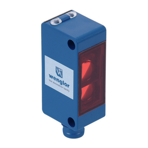
Spiegelreflexschranke zur Klarglaserkennung
Retro-Reflex Sensor for Clear Glass Recognition
Capteur optique pour objet transparent
BETRIEBSANLEITUNG
OPERATING INSTRUCTIONS
NOTICE D’INSTRUCTIONS
OKII403C0303
Bestimmungsgemäße Verwendung
Dieses wenglor-Produkt ist gemäß dem folgenden
Funktionsprinzip zu verwenden:
Spiegelreflexschranke
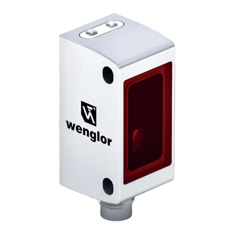
InoxSens ist die Hygieneserie von wenglor: InoxSens-
Sensoren zeichnen sich durch ihre innovative Bauform aus,
die Schmutz und Reinigungsmittel selbst abfließen lässt. Eine
Vielzahl an Komponenten bildet ein Komplettsystem, das
sich nahtlos in die Maschine integriert. Das lasergeschweißte
Edelstahlgehäuse aus V4A (1.4404/316L) ist korrosionsfrei
und reinigungsmittelbeständig. Die spaltfreie Befestigung mit
InoxLock und die unverlierbare Optik tragen zusätzlich zur
optimalen Eignung für reinigungsintensive Umgebungen bei.
Sicherheitshinweise
• Diese Anleitung ist Teil des Produkts und während der
gesamten Lebensdauer des Produkts aufzubewahren.
• Betriebsanleitung vor Gebrauch des Produkts sorgfältig
durchlesen.
• Montage, Inbetriebnahme und Wartung des vorliegenden
Produkts sind ausschließlich durch fachkundiges Personal
auszuführen.
• Eingriffe und Veränderungen am Produkt sind nicht
zulässig.
• Produkt bei Inbetriebnahme vor Verunreinigung schützen.
• Kein Sicherheitsbauteil gemäß EU-Maschinenrichtlinie.
Technische Daten
Reichweite 4000 mm
Bezugsreflektor/Reflexfolie RQ100BA
Schalthysterese < 5 %
Lichtart Rotlicht
Polarisationsfilter ja
Lebensdauer (Tu = 25 °C) 100000 h
max. zul. Fremdlicht 10000 Lux
Öffnungswinkel 3°
Versorgungsspannung 10…30 V DC
Stromaufnahme (Ub = 24 V) < 40 mA
Schaltfrequenz 1600 Hz
Ansprechzeit 313 µs
Anzugs-/Abfallzeitverzögerung (RS-232) 0…5 s
Temperaturdrift < 5 %
Temperaturbereich −10…60 °C
Spannungsabfall Schaltausgang < 2,5 V
Schaltstrom PNP Schaltausgang 200 mA
Reststrom Schaltausgang < 50 µA
kurzschlussfest ja
verpolungssicher ja
überlastsicher ja
verriegelbar ja
Teachmodus NT, MT, XT
Einstellart Teach-In
Gehäusematerial Edelstahl V4A
Optikabdeckung PMMA
Schutzart IP68/IP69K
Anschlussart M12×1
Schutzklasse III
Ausgangsfunktion PNP Öffner/Schließer
umschaltbar
RS-232 mit Adapterbox ja
Montagehinweise
Sensor so justieren und fest montieren, dass der Lichtfleck
auf den Reflektor fällt.
Einstellungen
Funktionen von PIN 2
Extern Teachen
Der Sensor besitzt einen Eingang für externes Teachen
(PIN 2). Über diesen kann durch Anlegen einer Spannung von
24 V (ca. 1 Sek.) der Schaltpunkt eingeteacht werden.
Umschalten zwischen den Teach-Modi
Für mindestens 10 Sekunden den Teacheingang auf 24 V
legen, bis die LED von einer schnellen in eine langsame
Blinkfrequenz wechselt.
Blinken TEACH Modus Öffner/Schließer
1× Normal Teachen NO
2× NC
3× Minimal Teachen NO
4×* NC
5× Maximal Teachen NO
6× NC
*Voreinstellung
• Jeweils ein kurzer Impuls auf dem Teacheingang schaltet
um einen Teachmodus weiter.
• Wenn der Teacheingang 15 Sekunden nicht betätigt wird,
schaltet der Sensor automatisch in den normalen Anzeige-
modus zurück.
• Teachvorgang entsprechend Einstellanweisung wiederholen.
Reset
Über folgende Resetsequenz auf PIN 2 können die Sensorein-
stellungen in den Auslieferungszustand zurückgesetzt werden:
Spannung
auf T in V
28 s
5 s
7 s
0 V
24 V 7 s
5 s 5 s
gelbe LED 01 ein aus ein aus ein blinkt 3×
Zeit in s
Bestätigt wird der durchgeführte RESET durch 3× blinken
der gelben LED 01 . Bei einer fehlerhaften Resetsequenz auf
PIN 2 blinkt die rote LED 02 und der Sensor wird nicht in den
Auslieferungszustand zurückgesetzt.
Weitere über Schnittstelle aktivierbare Funktionen:
Zeitverzögerung
Über die Schnittstelle kann im Sensor wahlweise eine Anzugs-
oder Abfallverzögerung aktiviert werden. Die Verzögerungs-
zeit ist einstellbar. Um den Sensor zu Parametrierzwecken an
einen PC mit RS-232-Schnittstelle anschließen zu können, ist
die Adapterbox A232 erforderlich.
Die Schaltfrequenz des Sensors kann über die Schnittstelle
von 1000 Hz (Voreinstellung) auf 1600 Hz umgestellt werden.
Schaltabstand
Der erreichbare Schaltabstand ist von dem verwendeten
Tripelreflektor abhängig. Der Nennschaltabstand wird mit dem
Reflektor Typ RQ100BA erreicht. Die erzielbare Reichweite
bei anderen Reflektoren entnehmen Sie bitte der folgenden
Tabelle:
Reflektor Reichweite Reflektor Reichweite
RQ100BA 0,00…4,0 m RE6210BM 0,00…0,7 m
RE18040BA 0,00…2,5 m RR25_M 0,00…1,0 m
RQ84BA 0,00…3,5 m RR25KP 0,00…0,55 m
RR84BA 0,00…4,0 m RR21_M 0,00…0,9 m
RE9538BA 0,00…1,5 m RE6151BH 0,00…1,5 m
RE6151BM 0,00…3,4 m ZRAE02B01 0,00…1,6 m
RR50_A 0,00…2,6 m ZRDS01R01 0,00…0,70 m
RE6040BA 0,00…3,2 m ZRME01B01 0,00…0,4 m
RE8222BA 0,00…1,9 m ZRME03B01 0,00…1,60 m
RR34_M 0,00…1,6 m ZRMR02K01 0,00…0,50 m
RE3220BM 0,00…0,8 m ZRMS02_01 0,00…0,7 m
Ursachen für das Ansprechen der Verschmutzungs-
meldung (rote LED)
• Verschmutzung des Sensors
• Zu große Entfernung zwischen Sensor und Objekt/Reflektor
• Falsche Montage
• Alterung der Sendedioden
Umweltgerechte Entsorgung
Die wenglor sensoric GmbH nimmt unbrauchbare oder irrepa-
rable Produkte nicht zurück. Bei der Entsorgung der Produkte
gelten die jeweils gültigen länderspezifischen Vorschriften zur
Abfallentsorgung.
Optik
Optic
Optique
+ Versorgungsspannung „+“
Supply Voltage “+”
Tension d’alimentation «+»
− Versorgungsspannung „0 V“
Supply Voltage “0 V”
Tension d’alimentation «0 V »
A Schaltausgang/ Schließer (NO)
Switching output (NO)
Sortie de commutation/ Fermeture (NO)
Schaltausgang/ Öffner (NC)
Switching output (NC)
Sortie de commutation/ Ouverture (NC)
T Teacheingang
Teach Input
Entrée apprentissage
Anschlussbilder
Connection Diagrams
Schémas de raccordement
Maßangaben in mm/ All dimensions in mm/ Mesures en mm
1 = Optische Achse
Optical Axle
Axe Optique
Ergänzende Produkte (siehe Katalog)
Complementary Products (see catalog)
Produits complémentaires (voir catalogue)
wenglor bietet Ihnen die passende Anschlusstechnik für Ihr
Produkt./
wenglor offers Connection Technology for field wiring./
wenglor vous propose la connectique adaptée à votre produit.
Passende Befestigungstechnik-Nr.
Suitable Mounting Technology No.
No. de Technique de montage appropriée
140 490
Passende Anschlusstechnik-Nr.
Suitable Connection Technology No.
Référence connectique appropriée
2
S02
Adapterbox A232
Adapter box A232
Adaptateur A232
Reflektor in Edelstahl Schutzgehäuse
Reflector in Stainless Steel Protection Housing
Réflecteur dans un boîtier de protection Inox
Reflektor, Reflexfolie
Reflector, Reflex Foil
Réflecteur, Feuille réflex
EU-Konformitätserklärung
EU Declaration of Conformity
Déclaration UE de conformité
Die EU-Konformitätserklärung finden Sie unter
www.wenglor.com im Download-Bereich des Produktes./
The EU declaration of conformity can be found on our website
at www.wenglor.com in download area./
Vous trouverez la déclaration UE de conformité sur
www.wenglor.com, dans la zone de téléchargement du produit.
01 = Schaltzustandsanzeige
Switching Status Indicator
Signalisation de l’état de commutation
02 = Verschmutzungsmeldung
= Contanimation Warning
= Signalisation d’encrassement
EN
FR
EN
FR
Proper Use
This wenglor product has to be used according to the
following functional principle:
Retro-Reflex Sensor
InoxSens is the hygiene series from wenglor. The innovative
design of InoxSens sensors allows contamination and clean-
ing agents to flow off by themselves. A variety of components
form a complete system which integrates seamlessly into the
machine. The laser welded stainless steel housing made of
V4A (1.4404/316L) is corrosion-free and resistant to cleaning
agents. Gap-free mounting with InoxLock and the captive
optics further contribute to these sensors’ optimal suitability
for cleaning-heavy environments.
Safety Precautions
• This operating instruction is part of the product and must be
kept during its entire service life.
• Read this operating instruction carefully before using the
product.
• Installation, start-up and maintenance of this product has
only to be carried out by trained personnel.
• Tampering with or modifying the product is not permissible.
• Protect the product against contamination during start-up.
• Not a safety component in accordance with the EU
Machinery Directive.
Technical Data
Range 4000 mm
Reference Reflector/Reflex Foil RQ100BA
Switching Hysteresis < 5 %
Light Source Red Light
Polarization Filter yes
Service Life (T = 25 °C) 100000 h
max. Ambient Light 10000 Lux
Opening Angle 3°
Supply Voltage 10…30 V DC
Current Consumption (Ub = 24 V) < 40 mA
Switching Frequency 1600 Hz
Response Time 313 µs
On-/Off-Delay (RS-232) 0…5 s
Temperature Drift < 5 %
Temperature Range −10…60 °C
Switching Output Voltage Drop < 2,5 V
PNP Switching Output/
Switching Current 200 mA
Residual Current Switching Output < 50 µA
Short Circuit Protection yes
Reverse Polarity Protection yes
Overload Protection yes
Lockable yes
Teach Mode NT, MT, XT
Setting Method Teach-In
Housing Stainless Steel 316L
Optic cover PMMA
Degree of Protection IP68/IP69K
Connection M12×1
Protection Class III
Output PNP NO/NC switchable
RS-232 with Adapterbox yes
Notice d’utilisation
Ce produit wenglor doit être utilisé selon le mode de
fonctionnement suivant :
Barrages sur réflecteur
InoxSens est la gamme de capteur au design hygienique de
wenglor : les capteurs InoxSens se caractérisent par leur type
de boîtier novateur qui laisse s’écouler d’eux-mêmes saletés
et produits de nettoyage. Une multitude de composants
forme un système complet qui se fond dans la machine. La
fixation sans interstice avec InoxLock et l’optique imperdable
contribuent elles aussi à une adaptation optimale de ces
capteurs à des environnements à nettoyage intensif.
Consignes de sécurité
• Cette notice d’utilisation fait partie intégrante du produit et
doit être conservée durant toute la durée de vie du produit.
• Lisez la notice d’utilisation avant la mise sous tension.
• L’installation, les raccordements et les réglages doivent être
effectués uniquement par du personnel qualifié.
• Toute intervention ou modification sur le produit est
proscrite.
• Lors de la mise en service, veillez à protéger l’appareil
d’éventuelles salissures.
• Aucun composant de sécurité selon la directive «Machines»
de l’Union Européenne.
Données techniques
Portée 4000 mm
Réflecteur de référence RQ100BA
Hystérésis de commutation < 5 %
Type de lumière Lumière rouge
Filtre de polarisation oui
Durée de vie (Tu = 25 °C) 100000 h
Ambiance lumineuse max. 10000 Lux
Angle d’ouverture 3°
Tension d’alimentation 10…30 V DC
Consommation (Ub = 24 V) < 40 mA
Fréquence de commutation 1600 Hz
Temps de réponse 313 µs
Temporisation à l’appel/retombée (RS-232) 0…5 s
Dérive en température < 5 %
Température d’utilisation −10…60 °C
Chute de tension sortie de commutation < 2,5 V
Courant commuté PNP sortie de
commutation 200 mA
Courant résiduel sortie de commutation < 50 µA
Protection contre les courts-circuits oui
Protection contre les inversions de polarité oui
Protection contre les surcharges oui
Verrouillable oui
Mode d’apprentissage NT, MT, XT
Mode de réglage Apprentissage
Matière du boîtier Inox V4A
Optique PMMA
Degré de protection IP68/IP69K
Mode de raccordement M12×1
Catégorie de protection III
Sortie PNP Ouverture/
Fermeture
commutable
RS-232 avec Adaptateur oui
Mounting instructions
Adjust and securely mount the Sensor such that the spot
strikes the reflector.
Adjustment
Functions of pin 2
External Teach-In
The Sensor is equipped with an input for external Teach-In
(pin 2). The switching point can be taught in via this input by
applying a voltage of 24 V for approximately 1 second.
Switching Between the Teach Modes
Apply 24 V to the Teach-In input for at least 10 seconds, until
the LED changes over from fast to slow blinking.
Blinking TEACH Mode NC/NO
1× Normal Teach-In NO
2× NC
3× Minimal Teach-In NO
4×* NC
5× Maximal Teach-In NO
6× NC
*preset configuration
• Each tome a brief pulse is applied to the Teach-In input,
switching to the next Teach-In mode occurs.
• If the Teach-In input is not activated for a period of
15 seconds, the Sensor is automatically switched back to
the normal display mode.
• Repeat the Teach-In process in accordance with the setup
instructions.
Reset
Via the following reset sequence on PIN 2 you can reset the
Sensor settings to the delivery status:
Voltage on
T in V
28 s
5 s
7 s
0 V
24 V 7 s
5 s 5 s
yellow LED 01 on off on off on 3×
blinking
time in s
The RESET is approved by 3× blinking of the yellow LED.
In case of a false reset sequence on PIN 2 the red LED blinks
and the Sensor isn’t reset to the delivery status.
Instructions de montage
Ajuster et installer fixement le capteur de façon à ce que la
spot atteigne le réflecteur.
Réglages
Fonctions du pin 2
Teach-In externe
Le capteur est doté d’une supplémentaire pour l’apprentis-
sage externe (pin 2). L’apprentissage du point de commuta-
tion peut être réalisé en appliquant une tension de 24 V DC
pendant 1 seconde environ.
Clignotement Mode
d’apprentissage Ouverture/
Fermeture
1× Apprentissage
normale
NO
2× NC
3× Apprentissage
minimale
NO
4×* NC
5× Apprentissage
maximale
NO
6× NC
*Préréglage
• Chaque fois qu’une brève impulsion est appliquée à
l’entrée Teach-In, le mode d’apprentissage change.
• Si l’entrée Teach-In n’est pas activée pendant 15 secondes,
le capteur retourne automatiquement au mode normal.
• Répétez les procédures d’apprentissage en suivant les
instructions de mise en service.
Reset
Avec cette séquence de reset sur le PIN 2, les configurations
du capteur peuvent être initialisées comme à la livraison:
Tension sur
T en V
28 s
5 s
7 s
0 V
24 V 7 s
5 s 5 s
Jaune LED 01 on off on off on clignote
3×
Temps en s
Le reset est confirmé si la LED jaune clignote 3×. Si la
séquence de reset sur le PIN 2 est fausse, la LED rouge cli-
gnote et le capteur n’est pas réinitialisé comme à la livraison.
Additional Functions for activation via the interface:
On-/Off-Delay
Either pull-in or release delay can be activated at the Sensor
via the interface. Delay time can be adjusted. The A232 adapt-
er box is required in order to be able to connect the Sensor.
The Switching Frequency can be changed via the interface
from 1000 Hz (delivery status) to 1600 Hz.
Switching distance
Maximum sensing distance depends upon the utilized triple
reflector. Nominal sensing distance is achieved with the type
RQ100BA reflector. Maximum ranges for other reflectors are
shown in the following table:
Reflector Range Reflector Range
RQ100BA 0,00…4,0 m RE6210BM 0,00…0,7 m
RE18040BA 0,00…2,5 m RR25_M 0,00…1,0 m
RQ84BA 0,00…3,5 m RR25KP 0,00…0,55 m
RR84BA 0,00…4,0 m RR21_M 0,00…0,9 m
RE9538BA 0,00…1,5 m RE6151BH 0,00…1,5 m
RE6151BM 0,00…3,4 m ZRAE02B01 0,00…1,6 m
RR50_A 0,00…2,6 m ZRDS01R01 0,00…0,70 m
RE6040BA 0,00…3,2 m ZRME01B01 0,00…0,4 m
RE8222BA 0,00…1,9 m ZRME03B01 0,00…1,60 m
RR34_M 0,00…1,6 m ZRMR02K01 0,00…0,50 m
RE3220BM 0,00…0,8 m ZRMS02_01 0,00…0,7 m
Causes for Triggering of Contamination Indication
(red LED)
• Contaminated Sensor
• Distance between the Sensor and the object/reflector is too
great
• Incorrect installation
• Aged emitter diodes
Proper Disposal
wenglor sensoric GmbH does not accept the return of unus-
able or irreparable products. Respectively valid national waste
disposal regulations apply to product disposal.
Désactiver le bouton TEACH
Si 24 V est appliqué de façon continue sur l’entrée Teach-In
externe, le capteur est verrouillé et est protégé des
manipulations involontaires.
Fonctions actives supplémentaires par l’interface:
A l’appel ou à la retombée
Par l’interface une temporisation à la l’appel ou à la retombée
peut être activée sur le détecteur. La temporisation peut être
ajustée. Pour récupérer les paramètres sur PC par l’interface
RS-232 un adapteur A232 est indispensable.
La fréquence de commutation peut être changée via l’inter-
face de 1000 Hz (livraison Usine) à 1600 Hz.
Distance de détection
La distance de détection avec un barrage photoélectrique
réflex se rapporte sur le reflecteur RQ100BA. D’autres réflec-
teurs donnent d’autres distances de détection. Voir le table
suivant.
Réflecteur Portée Réflecteur Portée
RQ100BA 0,00…4,0 m RE6210BM 0,00…0,7 m
RE18040BA 0,00…2,5 m RR25_M 0,00…1,0 m
RQ84BA 0,00…3,5 m RR25KP 0,00…0,55 m
RR84BA 0,00…4,0 m RR21_M 0,00…0,9 m
RE9538BA 0,00…1,5 m RE6151BH 0,00…1,5 m
RE6151BM 0,00…3,4 m ZRAE02B01 0,00…1,6 m
RR50_A 0,00…2,6 m ZRDS01R01 0,00…0,70 m
RE6040BA 0,00…3,2 m ZRME01B01 0,00…0,4 m
RE8222BA 0,00…1,9 m ZRME03B01 0,00…1,60 m
RR34_M 0,00…1,6 m ZRMR02K01 0,00…0,50 m
RE3220BM 0,00…0,8 m ZRMS02_01 0,00…0,7 m
Raisons liées à l’indication Encrassement (LED rouge)
• Capteur encrassé
• Distance entre le capteur et l’objet/réflecteur trop
importante
• Mauvaise installation
• Diodes d’émission en fin de vie
Mise au rebut
La société wenglor sensoric GmbH ne reprend ni les produits
inutilisables ni les produits irréparables. Veuillez respecter la
réglementation en vigueur en mettant le produit au rebut dans
un endroit prévu à cet effet par les autorités publiques.
This manual suits for next models

1

Other Wenglor Accessories manuals

Wenglor UF Series User manual

Wenglor

Wenglor UF Series User manual

Wenglor OPT2041 User manual

Wenglor

Wenglor OPT2041 User manual

Wenglor OHK202 User manual

Wenglor

Wenglor OHK202 User manual

Wenglor OPT2130 User manual

Wenglor

Wenglor OPT2130 User manual

Wenglor A1P05 User manual

Wenglor

Wenglor A1P05 User manual

Wenglor P1HJ1 Series User manual

Wenglor

Wenglor P1HJ1 Series User manual

Wenglor P1NK Series User manual

Wenglor

Wenglor P1NK Series User manual

Wenglor TIF352U0089 User manual

Wenglor

Wenglor TIF352U0089 User manual

Wenglor OY2TA104P0150E User manual

Wenglor

Wenglor OY2TA104P0150E User manual

Wenglor X1TA101MHT88 User manual

Wenglor

Wenglor X1TA101MHT88 User manual

Wenglor ODX202 User manual

Wenglor

Wenglor ODX202 User manual

Wenglor P1KH Series User manual

Wenglor

Wenglor P1KH Series User manual

Wenglor OPT2022 User manual

Wenglor

Wenglor OPT2022 User manual

Wenglor L1FL Series User manual

Wenglor

Wenglor L1FL Series User manual

Wenglor HD Series User manual

Wenglor

Wenglor HD Series User manual

Wenglor OPT2001 User manual

Wenglor

Wenglor OPT2001 User manual

Wenglor P1PA00 Series User manual

Wenglor

Wenglor P1PA00 Series User manual

Wenglor U1RT002 User manual

Wenglor

Wenglor U1RT002 User manual

Wenglor LN Series User manual

Wenglor

Wenglor LN Series User manual

Wenglor UMF402U035 User manual

Wenglor

Wenglor UMF402U035 User manual

Wenglor OPT2172-74 User manual

Wenglor

Wenglor OPT2172-74 User manual

Wenglor OPT2133 User manual

Wenglor

Wenglor OPT2133 User manual

Wenglor P1KY0 Series User manual

Wenglor

Wenglor P1KY0 Series User manual

Wenglor GM 04 User manual

Wenglor

Wenglor GM 04 User manual

Popular Accessories manuals by other brands

Axis F2115-R installation guide

Axis

Axis F2115-R installation guide

Dixon FloTech FT201-12 Maintenance & Operating Instructions

Dixon

Dixon FloTech FT201-12 Maintenance & Operating Instructions

Termozeta TZR62 instruction manual

Termozeta

Termozeta TZR62 instruction manual

La Crosse Technology TX141TH-BV4 quick start guide

La Crosse Technology

La Crosse Technology TX141TH-BV4 quick start guide

Omron ZJ-SD Series user manual

Omron

Omron ZJ-SD Series user manual

TeraBee TeraRanger Evo user manual

TeraBee

TeraBee TeraRanger Evo user manual

FRÄNKISCHE profi-air 180/300 Remote control manual

FRÄNKISCHE

FRÄNKISCHE profi-air 180/300 Remote control manual

ZEN AROME BOLEA instruction manual

ZEN AROME

ZEN AROME BOLEA instruction manual

Vision ZF 5201 IN-5 Installation & operation manual

Vision

Vision ZF 5201 IN-5 Installation & operation manual

Lightolier Lytecaster 1152 specification

Lightolier

Lightolier Lytecaster 1152 specification

Autonics BRQ Series product manual

Autonics

Autonics BRQ Series product manual

Sterilize+ UV-C SANITIZING TOWER manual

Sterilize+

Sterilize+ UV-C SANITIZING TOWER manual

Winsen ME3-HF manual

Winsen

Winsen ME3-HF manual

BEA VIO-ST user guide

BEA

BEA VIO-ST user guide

Vixen AP Equatorial Mount instruction manual

Vixen

Vixen AP Equatorial Mount instruction manual

Isotek EVO3 GEMINI installation instructions

Isotek

Isotek EVO3 GEMINI installation instructions

Samsung F-SS-PRES-001 quick start guide

Samsung

Samsung F-SS-PRES-001 quick start guide

Maxim Integrated MAXREFDES220 manual

Maxim Integrated

Maxim Integrated MAXREFDES220 manual

manuals.online logo
manuals.online logoBrands
  • About & Mission
  • Contact us
  • Privacy Policy
  • Terms and Conditions

Copyright 2025 Manuals.Online. All Rights Reserved.