IntroductIon
This User Guide contains warnings and guidance for correct and safe operation of the product. These instructions
must be followed at all times. wenglorTPL will not be held responsible for problems caused by using the product
contrary to these instructions and the Warranty will be deemed invalid.
unpackIng
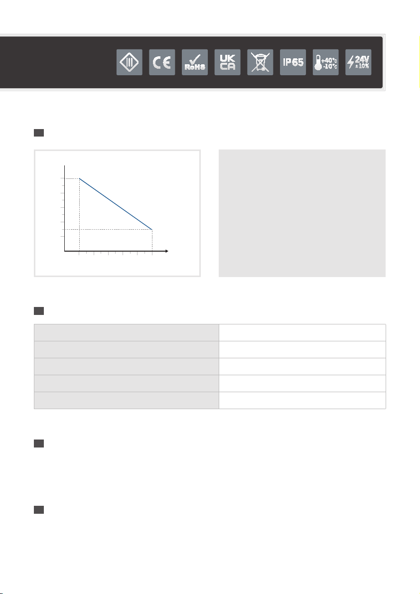
rISk claSS
The applicable Standard EN-62471 classies LED Lighting into 4 classes according to their degree of hazard severity.
The table below summarises the risks associated with our standard products.
BEWARE: infrared light is invisible to the eye.
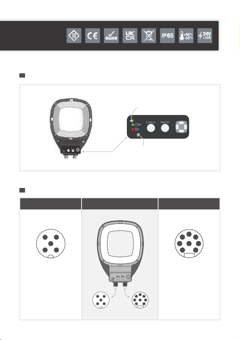
Please refer to LED Indicators on the product
to determine if it is operating.
Color Class Risk
White WHI, Red
625nm, Cyan 505 nm 0none
IR 860 nm 1low
wenglorTPL can provide guidance notes to minimise
photo-biological risks, including the nominal mini-
mum operating distance. Please contact wenglorTPL
through your usual representative for this information.
wenglorTPL recommends the use of protection glasses.
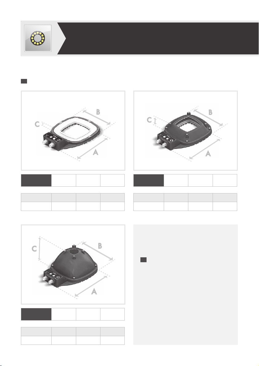
lMrXxxx
operatIng InStructIonS
This product is packed at the factory using suitable materials for safe transport. To open thepackage, do not use
any cutting blade to avoid damaging the product(s). Please use the delivered accessories ifneeded. (Donot use any
other products or equivalents to replace the delivered accessories).
In the event of damage occurring during shipping, it must be reported to the carrier at time of delivery (including
noting the damage in writing on the delivery documents). It is also your responsibility to notify wenglorTPL in wri-
ting of the damage within 24 hours of receipt of the package. If these instructions are not followed, wenglorTPL
reserves theright not to accept requests for return and exchange of damaged products.