manuals.online logo
Brands
  1. Home
  2. •
  3. Brands
  4. •
  5. Werac
  6. •
  7. Safety Equipment
  8. •
  9. Werac WN 304-4 Parts list manual

Werac WN 304-4 Parts list manual

This manual suits for next models

3

Other Werac Safety Equipment manuals

Werac SAFETY 40 Parts list manual

Werac

Werac SAFETY 40 Parts list manual

Werac WN 304-3 Parts list manual

Werac

Werac WN 304-3 Parts list manual

Popular Safety Equipment manuals by other brands

Lanex PB-20 instruction manual

Lanex

Lanex PB-20 instruction manual

SKYLOTEC ANCHOR ROPES Instructions for use

SKYLOTEC

SKYLOTEC ANCHOR ROPES Instructions for use

Besto Buoyancy Aid 50N Instructions for use

Besto

Besto Buoyancy Aid 50N Instructions for use

TEUFELBERGER NODUS Manufacturer's information and instructions for use

TEUFELBERGER

TEUFELBERGER NODUS Manufacturer's information and instructions for use

Troy Lee Designs Tbone Product owners manual

Troy Lee Designs

Troy Lee Designs Tbone Product owners manual

Innova Xtirpa Instruction and safety manual

Innova

Innova Xtirpa Instruction and safety manual

bolle SAFETY B810 quick start guide

bolle SAFETY

bolle SAFETY B810 quick start guide

SHENZHEN FANHAI SANJIANG ELECTRONICS A9060T instruction manual

SHENZHEN FANHAI SANJIANG ELECTRONICS

SHENZHEN FANHAI SANJIANG ELECTRONICS A9060T instruction manual

Hiltron security POWER8E Installation and use manual

Hiltron security

Hiltron security POWER8E Installation and use manual

Salewa MTN SPIKE user manual

Salewa

Salewa MTN SPIKE user manual

Hatco B-950P installation guide

Hatco

Hatco B-950P installation guide

Sitec TX MATIC operating manual

Sitec

Sitec TX MATIC operating manual

TEUFELBERGER GRIP 12 Manufacturer's information and instructions for use

TEUFELBERGER

TEUFELBERGER GRIP 12 Manufacturer's information and instructions for use

MSA PremAire System Operation and instructions

MSA

MSA PremAire System Operation and instructions

AMC 1022M Series instruction manual

AMC

AMC 1022M Series instruction manual

Trinity CASS S3 Assembly manual

Trinity

Trinity CASS S3 Assembly manual

CMC Helitack HotSeat quick guide

CMC

CMC Helitack HotSeat quick guide

ACM SAFETY D200 Instructions and warnings

ACM

ACM SAFETY D200 Instructions and warnings

manuals.online logo
manuals.online logoBrands
  • About & Mission
  • Contact us
  • Privacy Policy
  • Terms and Conditions

Copyright 2025 Manuals.Online. All Rights Reserved.

technical description
Technische Beschreibung
description technique
Am Rodaugraben 2, D-76744 Wörth, Telefon +49 (0)7271 / 6136
Telefax +49 (0)7271 / 8932
Stand, actualised, actualisé 31.05.2005
Multiple accident protection light barrier device
Mehrfach Unfallschutz-Lichtschranke
Barrage photoélectrique multiple pour protection de la personne
for applications in accordance with EN 954-1 up to the category 4
für Anwendungen gemäß EN 954-1 bis Kategorie 4
pour des applications conformément à EN 954-1 jusqu'à la catégorie 4
switching device to wire alternatively:
wahlweise Steuergerät für den Anschluss von:
appareil de commande pouvant connecter:
accident protection light barrier
Unfallschutz-Lichtschranke
nombre de barrages photoélectriques 1 - 4 5 - 8
plastic-housing
Kunststoffgehäuse
boîtier en plastic IP 65 WN 304-4 WN 308-1
sheet-metal-housing
Blechgehäuse
boîtier en tôle IP 20 WN 314-4 WN 318-1
●Acceptance test according to self monitoring prEN 61496-1:2001 ESPE type 4 by „Prüf und Zertifizierungsstelle im BG-
PRÜFZERT. Fachausschuss Maschinenbau, Hebezeuge, Hütten- und Walzwerksanlagen“.
●Adaptable for one to four respectively five to eight light barrier devices with a DIP-switch.
●The light barrier device which causes a disconnection is displayed by a LED in the emitter.
●Selective receivers with low sensitivity for foreign light and light pulses.
●Geprüft nach prEN 61496-1:2001 BWS Typ 4 von der Prüf und Zertifizierungsstelle im BG-PRÜFZERT.
Fachausschuss Maschinenbau, Hebezeuge, Hütten- und Walzwerksanlagen
●Anpassung an ein bis vier bzw. fünf bis acht Lichtschranken mit DIP-Schalter.
●LED Anzeige im Sender der Lichtschranke, die die Abschaltung verursacht hat.
●Empfänger mit Auftastung, unempfindlich gegen Fremdlicht und Impulslicht.
●Contrôle selon prEN 61496-1:2001 d’après „Prüf und Zertifizierungsstelle im BG-PRÜFZERT. Fachausschuss
Maschinenbau, Hebezeuge, Hütten- und Walzwerksanlagen“ et degré d’exigence ESPE Type 4
●Adaptation de un à quatre ou bien cinq à huit barrages photoélectriques avec interrupteur DIP.
●Indication du barrage photoélectrique qui a produit l’interruption, avec LED dans l’émetteur.
●Récepteur à déclenchement insensible à lumière étrangère ou lumière d’impulsion.
Deutsches Patent
Nr. 38 40 493
WN 304, WN 314, WN 308, WN 318 / Seite 2 von 24 page 2 of 24
Am Rodaugraben 2, D-76744 Wörth, Telefon +49 (0)7271 / 6136
Telefax +49 (0)7271 / 8932
31.05.2005
working description
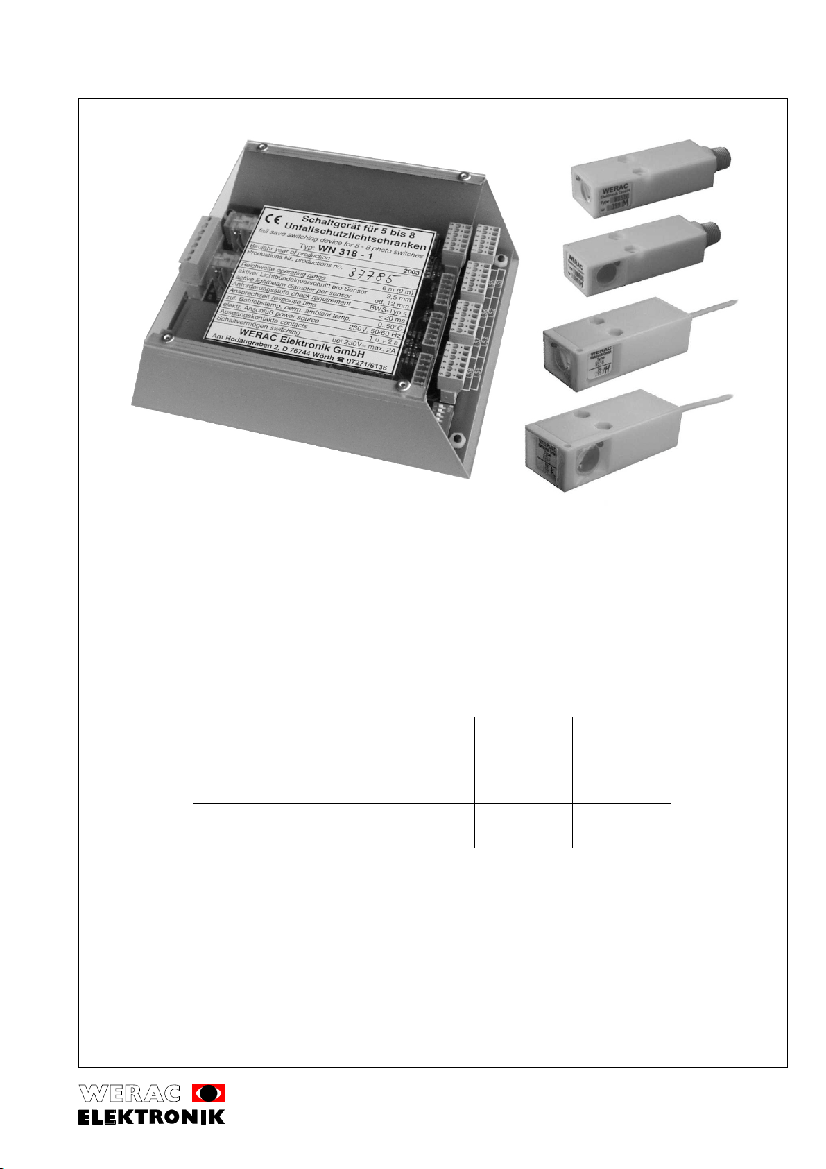
1.) Funktionsbeschreibung
description du fonctionnement
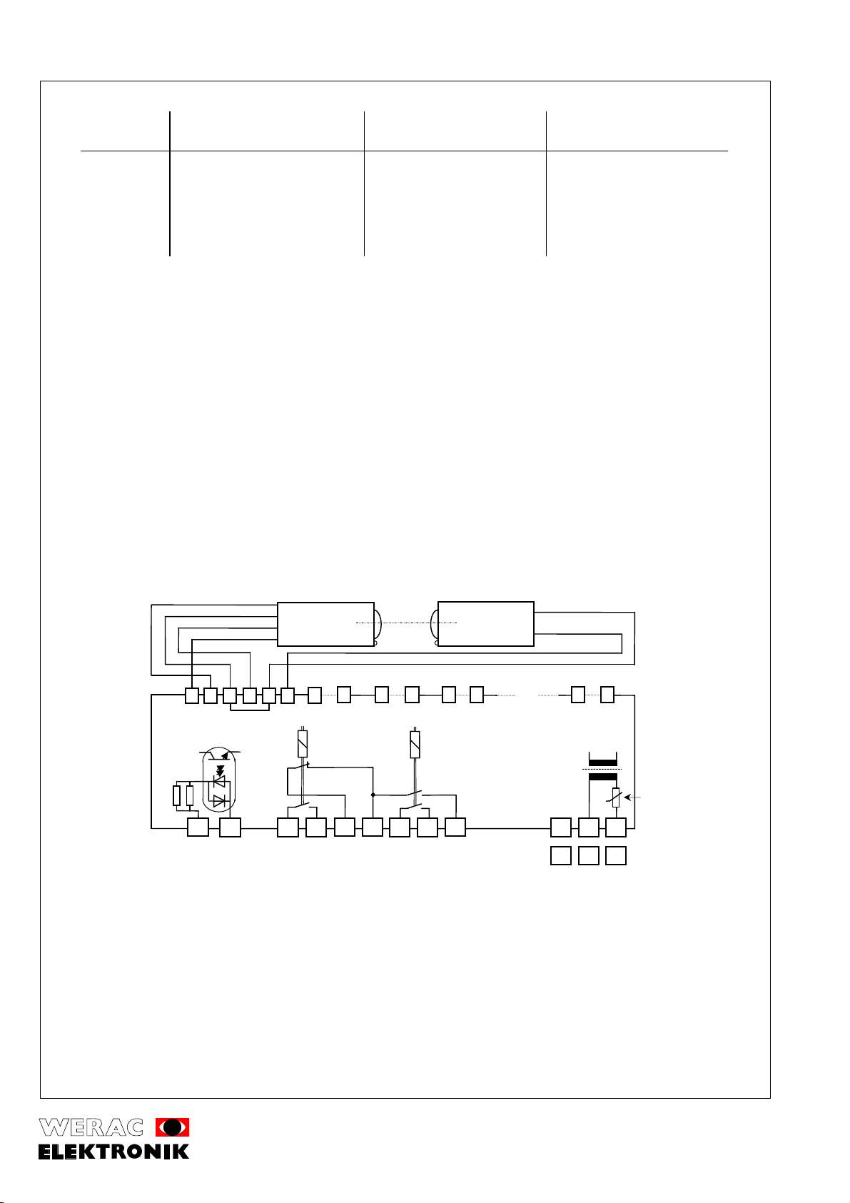
First the control device WN 304, WN 314, WN 308 and WN 318 must be released by the test inputs (T1, T2). The self
monitoring logic starts and checks the photo switches in serial, each with emitter on and off. As long as the result is correct, that
means the light beams are free and without internal or external failures, the output relays A and B are energised. Each of these
relays delivers one normally opened contact for the external use. If one relay is wrong the other is deenergised and in this case
in a save condition. The switching position of the output relays is shown at the red and green LED. Depending to the use of the
ESPE, the external indicator module WA 2 (indicated on page 18) is to be well visibly attached in the proximity of the sensors. If
a light beam is interrupted the LED in the according emitter lights up till the next start. Thereby it is easier to find the reason why
the machine has stopped, especially if the failure is not static. After power-ON or a switch off by a photo switch, which also
influences the following circuit, all emitter-LED’s stay deenergised. A differentiation of the cause of switch off between the photo
switch and the safety microswitches is thereby easier to make. The device is powered via a transformer and a PTC-fuse form
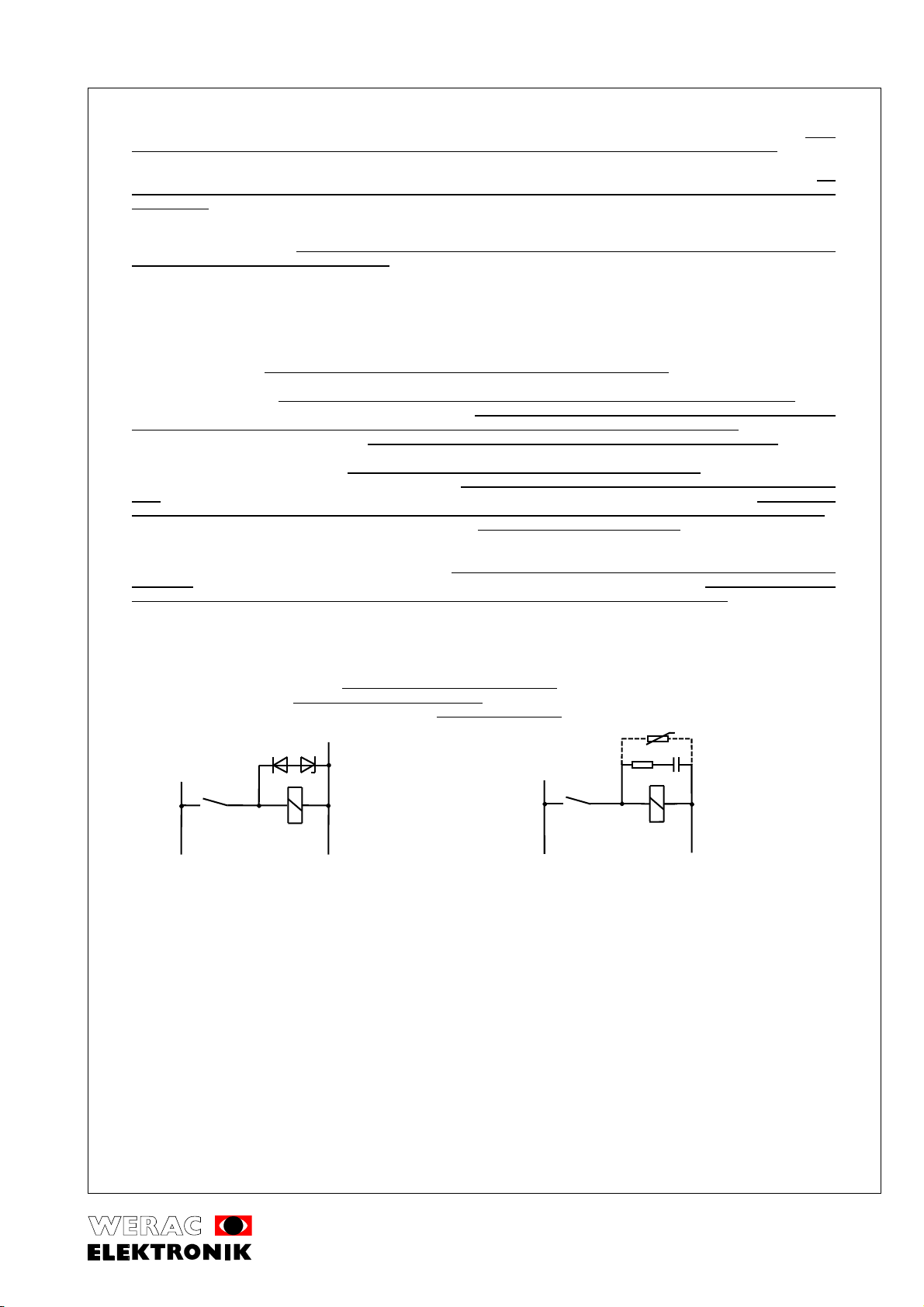
the source. The restart interlock must be realised by a following circuit with relays or contactors as shown under point 6.
Das Steuergerät WN 304, WN 314, WN 308 und WN 318 muss zunächst über die Testeingänge T1 und T2 freigegeben
werden. Die selbstüberwachende Logik aktiviert nun die Lichtschranken der Reihe nach und überprüft sie bei ein- und
ausgeschaltetem Sender. Solange die Abfrage richtige Ergebnisse liefert, d.h. die Lichtschranken sind frei und ohne
interne und externe Störungen, werden die Ausgangsrelais A und B angesteuert. Jedes dieser Relais liefert einen
Ausgangskontakt zur weiteren Verarbeitung. Bei Ausfall eines der Relais bleibt das zweite Relais abgefallen, d.h. im
sicheren Zustand. Der Schaltzustand der Ausgangsrelais wird über eine rote und grüne LED angezeigt. In
Abhängigkeit der Verwendung der BWS ist das auf Seite 18 angegebene externe Anzeigemodul WA 2 in der Nähe der
Sensoren gut sichtbar anzubringen. Nach einer Störung wird die LED im Sender, der die Unterbrechung ausgelöst hat,
aktiviert. Dadurch kann auch bei kurzen Störungen der Grund für die Abschaltung festgestellt werden. Dies vereinfacht
die Fehlersuche und erhöht die Betriebssicherheit. Nach Netz EIN oder einer Abschaltung durch einen
Sicherheitskontakt, der auch auf die Nachfolgeschaltung wirkt, bleiben alle Sende-LEDs aus. Eine Unterscheidung der
Abschaltursache zwischen den Lichtschranken und den Sicherheitskontakten ist dadurch einfach erkennbar. Die
Stromzufuhr erfolgt über einen Trafo mit Kaltleitersicherung vom Netz. Die Wiederanlaufsperre muss durch die
Nachfolgeschaltung, wie unter Punkt 6 beschrieben, erfolgen.
L’appareil de commande WN 304, WN 314, WN 308 et WN 318 doit être dégagé sur les signaux de test T1 et T2. La logique
auto-contrôlant démarre et contrôle alors les barrages photoélectriques, l’un après l’autre, et les vérifie, l’émetteur étant en
marche et en arrêt. Tant que l’opération est correcte, les barrages photoélectriques sont libres et sans interférences soit interne
ou externe, les impulsions sont livrées à un transformateur sélectif de sortie. Celui-ci distribue les relais des sorties A et B.
Chacun de ces relais donne un contacte de sortie pour l’utilisation suivante. En cas de défection d’un relais, l’autre reste dans
les conditions de sécurité. La position de l’interrupteur du relais de sortie est indiquée par un LED rouge et vert. Dépendant de
l’emploi du ESPE, le module externe de signalisation WA2 d’après l’indication sur la page 18, devra être mis de façon bien
visible près des détecteurs. Après un incident, le LED sera activé dans l’émetteur qui a déclenché l’interrupteur. Ainsi la raison
de l’arrêt peut aussi être trouvée facilement. Ceci non seulement simplifie la recherche de l’erreur mais aussi élève le taux de
sécurité. Après la mise en circuit du courant ou après un arrêt de courant effectué par un contacte de sécurité (fusible) que
s’active aussi sur le contacte suivant, tous les LEDs émetteurs restent en état d’arrêt. La différence de l’interrupteur entre les
barrages photoélectriques et les contactes de sécurité est donc simple de reconnaître. L’alimentation de courant a lieu par un
transformateur muni de fusible thermistor PTC. Le blocage de remise en marche doit alors être fait par le contacte suivant
comme indiqué sur point 6.
test
2.) Testung
test
Before the machine starts it is necessary to check if the whole system works correctly. The machine control must release the
test by switching off the current through the optocoupler (terminal T1 and T2). To start the control device and for the whole
running period a current flow trough the optocoupler is necessary.
Das System muss vor jeder Betriebsaufnahme auf einwandfreie Funktion geprüft werden. Die Testung wird von der
Folgesteuerung ausgelöst, durch Aufhebung des Stromflusses durch den Optokoppler (Klemmen T1 und T2). Zum
Start der Unfallschutz-Lichtschranke und für die Betriebsdauer ist ein Stromfluss durch den Optokoppler erforderlich.
Avant la mise en marche de la machine, il est nécessaire de vérifier tout le système. La machine de contrôle doit déclencher le
test en coupant le courant à travers le coupleur optique (bornes T1 et T2). Pour démarrer le barrage photoélectrique de sécurité
et pendant toute la période de fonctionnement, le courant doit passer à travers du coupleur optique.
optical adjustment and setting the number of sensor pairs
3.) Optische Ausrichtung und Einstellung der Lichtschrankenanzahl
ajustage optique et ajustage du nombre de barrages photoélectriques
The number of light barrier devices (1-4 or 5-8) is set with the DIP-switches (S2) in accordance with the following table.
Die Lichtschrankenanzahl (1-4 bzw. 5-8) wird mit den DIP-Schaltern (S2) gemäß nachstehenden Tabellen eingestellt.
Le nombre de barrages photoélectriques est ajusté à l’aide de l’interrupteur S2 selon le tableau suivant:
light barriers
Lichtschranken (LS)
barrages photoélectriques
DIP-switch 2
DIP-Schalter 2
DIP-commutateur 2
light barriers
Lichtschranken (LS)
barrages photoélectriques
DIP-switch 2
DIP Schalter 2
DIP-commutateur 2
1 2 3 4 5 1 2 3 4
1 LS off off on on off 5 LS off off on on
2 LS on off off on off 6 LS on off off on
3 LS off on on off on 7 LS off on on off
4 LS on on off off on 8 LS on on off off
WN 304, WN 314, WN 308, WN 318 / Seite 3 von 24 page 3 of 24
Am Rodaugraben 2, D-76744 Wörth, Telefon +49 (0)7271 / 6136
Telefax +49 (0)7271 / 8932
31.05.2005
All photo switches must be adjusted before putting into operation. To adjust photo switch 1 put DIP-switch (S1) A and 1 in ON-
position (for photo switch 2 acc. A and 2...). The LED in the selected emitter lights up. If the light beams are in function the
yellow LED in the receiver lights up. After this emitter and receiver must be optimised in both axes. After the adjustment all DIP-
switches must be switched off. The check of the adjustment safety is possible by reducing the emitting power of the emitter. To
do that put DIP-switch B in OFF-position. It is necessary to readjust if a light barrier device does not work. This test should be
made at the maintenance every year and it is possible to do the test with running machine. Attention: In regular function the DIP-
switches A and 1 to 4 respectively 1 to 8 are OFF, B is ON
For service people who work often with our accident protection light barriers, we recommend the use of our measure-receiver
and our optic light filter.
Note: If the number of the light barrier devices and the position of the DIP-switch (S2) do not correspond, the output delays will
stay deenergised.
Vor der Inbetriebnahme müssen die einzelnen Lichtstrahlen justiert werden. Dazu wird mit den DIP-Schaltern (S1) A
und 1-4 bzw. 1-8 (entsprechend Lichtschranke 1-4 bzw. 1-8) die jeweilige Lichtschranke aktiviert. Die Sendeanzeige
LED leuchtet. Sobald Sender und Empfänger richtig ausgerichtet sind, leuchtet die gelbe Schaltstellungsanzeige im
Empfänger auf. Anschließend Sender und Empfänger in beiden Achsen optimieren und am Schluss der Justage die
DIP-Schalter in Position AUS stellen. Die Prüfung der Justage-Sicherheit kann durch eine ~30% Reduzierung der
Sendeleistung erfolgen. Dazu muss der DIP-Schalter B in Stellung AUS geschaltet werden. Sofern eine Lichtschranke
nicht mehr funktioniert, ist eine Nachjustage erforderlich. Dieser Test ist beim jährlichen Kundendienst sinnvoll und
kann bei laufender Maschine erfolgen. Bitte beachten: Im Normalbetrieb sind die DIP-Schalter A und 1-4 bzw. 1–8 in
AUS-, der Schalter B in EIN-Stellung.
Kundendienstleuten die häufig mit unseren Unfallschutz-Lichtschranken arbeiten, empfehlen wir die Verwendung
unseres Messempfängers und unserer Graufilter: (getrenntes Datenblatt anfordern)
Hinweis: Sofern die Zahl der angeschlossenen Lichtschranken nicht mit der Einstellung des DIP-Schalters S2
übereinstimmt, können die Ausgangsrelais nicht anziehen.
Avant la mise en marche, chaque rayon lumineux doit être ajusté. Pour cela, le barrage photoélectrique respectif est activé par
les commutateurs DIP (S1) A et 1-4 ou bien 1-8 qui correspondent aux barrages photoélectriques 1-4 ou bien 1-8. L’indicateur
de l’émetteur s’allume. Dès que l’émetteur et le récepteur sont correctement ajustés, l’indicateur jaune de la touche du
récepteur s’allume. Ensuite l’émetteur et le récepteur doivent être optimisés dans le sens des deux axes et à la fin de l’ajustage,
mettre l’ interrupteur DIP en position d’arrêt. Un examen complémentaire de l’ajustage sécurité peut être fait par une réduction
de - 30% de la capacité de transmission. Pour cela on doit mettre en position d’arrêt le commutateur DIP „B“. En cas où un
barrage photoélectrique ne fonctionne plus, un ré ajustage est donc nécessaire. Ce test est recommandé lors du service après-
vente annuel et peut être réalisé avec la machine en état de marche. Attention: en fonctionnement normal les commutateurs
DIP „A“ et 1 à 4 ou bien 1 à 8 sont en état d’arrêt, mais mettre le „B“ en circuit.
Les personnes chargées du service- après vente de nos barrages photoélectriques doivent utiliser aussi notre appareil de
contrôle des récepteurs ainsi que notre feuille technique grise (celle-ci peut être fournie sur demande) Observation: lorsque le
nombre de barrages photoélectriques ne s'accorde pas au nombre d'interrupteurs S2 à ajuster, les relais de sortie ne
fonctionnent pas.
technical data for the switching device WN 304-4 and WN 308-1
4.) Technische Daten für Steuergerät Typ WN 304-4 und WN 308-1
données techniques pour l’appareil de commande WN 304-4 et WN 308-1
Standard: ESPE type 4 prEN 61496-1:2001
Anforderungsstufe: BWS Typ 4 prEN 61496-1:2001
degré exigé: ESPE Type 4 prEN 61496-1:2001
response time
Ansprechzeit <20 ms
temps de réponse
permanent ambient temperature
zulässige Betriebsumgebungstemperatur 0...50 °C
température ambiante pour le fonctionnement
supply voltage
Betriebsspannung 230 V ± 10% 48 – 62 Hz
tension du réseau
differing power source
Abweichende Netzspannung z.B. 24 V~, 42 V~, 110 V~
tension différente
power consumption
Leistungsaufnahme ca. 6 VA
puissance absorbée
output contacts: max. switching voltage
Ausgangskontakte: max. Schaltspannung 250 V~
contactes de sortie: commutateur de tension max.
output contacts: max. switching current at 230 V~
Ausgangskontakte: max. Schaltstrom bei 230 V~ (ind. Last) 2 A
contactes de sortie: commutateur de courant à 230 V~
output contacts: max. switching rate
Ausgangskontakte: max. Schalthäufigkeit 2 /s
contactes de sortie: fréquence de commutation max.
WN 304, WN 314, WN 308, WN 318 / Seite 4 von 24 page 4 of 24
Am Rodaugraben 2, D-76744 Wörth, Telefon +49 (0)7271 / 6136
Telefax +49 (0)7271 / 8932
31.05.2005
output contacts: life time with contactor for 5,5 kW 3 phase motor
Ausgangskontakte: min. Schaltspiele 10
7
mit Schütz für 5,5 kW 3-Phasen-Motor
contactes de sortie: : jeu min commutation max. avec contacteur pour 5,5 kW moteur triphasé
turn-on delay
Einschaltverzögerung < 70 ms
enclencher retard
housing ABS, colour grey, sealing IP 65
Gehäuse ABS, Farbe grau, Schutzart IP 65
boîtier ABS, gris, degré de protection IP 65
electrical connection screw-connectors
elektrischer Anschluss Klemmstecker, bis 2,5 mm²
branchement électrique connecteurs à pinces
indicator for switching position of relay red, green
Schaltstellungsanzeige der Ausgangsrelais rot, grün
touche du relais de sortie rouge, vert
test input external voltage 10-50 V≅
Testeingang Fremdspannung 10-50 V≅
≅≅
≅
issue de test voltage externe 10-50 V
≅
The outputs are contrary to the light barrier devices separated from the source; according to the overvoltage-category II (rated
voltage up to 300 V, transient overvoltage up to 2.5 kV)
Die Ausgänge sind gegenüber den Lichtschranken netzgetrennt; gemäß Überspannungskategorie II (Nennspannung
bis 300 V, transiente Überspannung bis 2.5 kV).
Au contraire des barrages photoélectriques, les sorties sont avec tension séparée selon surtension II (tension nominale jusque
300 V, surtension transitoire jusque 2,5 kV)
It is possible to connect all our emitters WS 50 - WS 531 (standard and small type) and receivers WE 50 - 531 (standard and
small type). The maximum line length from the emitters and the receivers to the switching device is 25 m.
Es können alle Sender WS 50 - WS 531 (normale und kleine Typen) und alle Empfänger WE 50 - 531 (normale und
kleine Typen) angeschlossen werden. Die maximale Leitungslänge von Sendern und Empfängern zum Steuergerät
beträgt 25 m.
Il est possible de connecter tous les émetteurs WS 50 - WS 531 (soit modèles standard ou plus petits) et les récepteurs
WE 50 - 531 (aussi standard ou petits). La longueur maximale du câble de l’émetteur et récepteur jusqu’ à l’appareil de
commande est de 25 mètres.
technical data for the switching device WN 314-4 or WN 318-1
Technische Daten für Steuergerät Typ WN 314-4 oder WN 318-1
données techniques pour l’appareil de commande WN 314-4 et WN 318-1
Like WN 304-4 and WN 308-1 but with metal-sheet-housing to snap on a TS 35 for installation in a switch cabinet. Sealing: IP
20. The switch cabinet has to come up to the soiling-category 2 according to DIN VDE 0110. (In normal case it is IP 54.) The
often needed switching device for the connection of two light barrier devices can be ordered under type number WN 312-4. It is
identical with the type WN 314-4, but without the DIP-switch 2 and the plugs for light barrier devices three and four.
Wie vor, jedoch mit Blechgehäuse zum Aufschnappen auf TS 35 für Schaltschrankeinbau. Schutzart IP 20; Der
Schaltschrank muss mindestens der Verschmutzungskategorie 2 gemäß DIN VDE 0110 entsprechen (In der Regel ist
dies IP 54). Das häufig benötigte Steuergerät für den Anschluss von 2 Lichtschranken kann als Typ WN 312-4 bezogen
werden. Es ist identisch mit dem Typ WN 314-4, ohne den DIP Schalter 2 und die Stecker für die dritte und vierte
Lichtschranke.
Les données techniques sont identiques à celles des WN 304-4 ou WN 318-1 mais ici il y a un boîtier métallique avec fixation
immédiate sur un TS 35 pour l’installation dans une armoire de distribution de protection selon IP 20. L’armoire de distribution
devra accomplir d’au moins la catégorie d’encrassage 2- d’après DIN VDE 0110. (Par règle générale il s’agit de IP 54).
L’appareil de commande plus fréquent est le modèle WN 312-4 pour le branchage de deux barrages photoélectriques et peut
être commandé chez nous. Il est identique au WN 314-4 mais sans le commutateur DIP 2 et aussi sans la prise pour le 3ème
et 4ème barrage photoélectrique.
technical data for the emitter in straight and angular model
Technische Daten für Sender in Normal- und Winkelausführung
données techniques pour l’émetteur en modèle normal et angulaire
Standard: ESPE type 4 prEN 61496-1:2001
Anforderungsstufe: BWS Typ 4 prEN 61496-1:2001
degré exigé: ESPE Type 4 prEN 61496-1:2001
infrared impulse light (880 nm) focused to ±2°
Infrarot Impulslicht (880 nm) gebündelt auf ± 2°
lumière à impulsion infrarouge (880 nm) reliée à ±2°
permanent ambient temperature
zulässige Umgebungstemperatur 0...50 °C
température ambiante pour le fonctionnement
yellow transmitting indicator LED
Sendeanzeige mit gelber LED
touche émettrice avec LED jaunes
WN 304, WN 314, WN 308, WN 318 / Seite 5 von 24 page 5 of 24
Am Rodaugraben 2, D-76744 Wörth, Telefon +49 (0)7271 / 6136
Telefax +49 (0)7271 / 8932
31.05.2005
housing: ABS, colour yellow, sealing IP 65
Gehäuse: ABS, Farbe gelb, Schutzart IP 65
boîtier: ABS, jaune, type de protection IP 65
3 m cable (max. 25 m) 2 x 0.25 mm
2
, stripped ends with multicore cable ends
3 m Anschlusskabel (max. 25 m) 2 x 0,25 mm², freie Enden mit Adernendkrallen
3 m de câble d’alimentation (max. 25 m) 2 x 0.25 mm
2
, extrémité libre dénudée avec crampon pour brin
Also available with: plug M12x1 instead of cable output. Type no. with additional C (e.g. WS 53C).
Alternativ mit Stecker M12x1 anstelle Kabelausgang. Die Typennr. erhält zusätzlich den Buchstaben C (z.B. WS 53C).
Alternative avec fiche M12x1. Type numéro avec C additionnel (p.ex. WS 53C).
type
Type
type
optics
Optik
optique
style
Baugröße
style
range
Reichweite
portée
active light beam Ø d
aktiver Lichtbündel Ø d
faisceau lumineux actif Ø d
WS 50 ahead, vorne, devant standard, normal, standard 6 m 12 mm
WS 501 ahead, vorne, devant standard, normal, standard 9 m 12 mm
WS 52 lateral, seitlich, latéral standard, normal, standard 6 m 12 mm
WS 521 lateral, seitlich, latéral standard, normal, standard 9 m 12 mm
WS 51 ahead, vorne, devant small, klein, petit 6 m 9.5 mm
WS 511 ahead, vorne, devant small, klein, petit 8 m 9.5 mm
WS 53 lateral, seitlich, latéral small, klein, petit 6 m 9.5 mm
WS 531 lateral, seitlich, latéral small, klein, petit 8 m 9.5 mm
The emitters WS 501 and WS 521 with enhanced range must be operated with the according receivers WE 501, WE 521. The
small emitters WS 511 and WS 531 with enhanced range must be operated with the according receivers WE 511, WE 531.
Die verstärkten Sender WS 501 und WS 521 dürfen nur mit den Empfängern WE 501 und WE 521 betrieben werden,
dies gilt auch für die verstärkten kleinen Sender WS 511 und WS 531, die nur mir den kleinen Empfängern WE 511 und
WE 531 betrieben werden dürfen.
Indication : Les émetteurs renforcés WS 501 et WS 521 ne devront être utilisés qu’avec les récepteurs WE 501 et WE 521. Ceci
est aussi valable pour les petits émetteurs WS 511 et WS 531, qui alors ne doivent être utilisés qu’avec les plus petits
récepteurs WE 511 et WE 531.
technical data for the receiver in straight and angular model
Technische Daten für Empfänger in Normal- und Winkelausführung
données techniques pour le récepteur en modèle normal et angulaire
phototransistor focused to ±2°, preamplifier and switching amplifier
Fototransistor Sichtwinkel: ±2°, Vorverstärker, Sch altverstärker
phototransistor angulaire ±2°, amplificateur préliminaire, commutateur amplificateur
amplification only while the according emitter works to reduce failure from foreign pulse lights
Sendeimpulsauftastung zur Erhöhung der Sicherheit gegen Fremdstörungen und Impulslicht
émetteur d’impulsion de déclement pour l’augmentation de la sécurité contre les interférences et les impulsions étrangères
yellow switching position LED for adjustment.
Schaltstellungsanzeige mit gelber LED zur Justierungshilfe
commutateur indicateur de position avec LED jaunes comme aide pour l’ajustement.
terminals protected against short circuits and changes
Anschlüsse verpolgeschützt und kurzschlussfest
branchements avec pôle protégé et résistant aux court-circuit
housing: ABS, colour yellow, sealing IP 65
Gehäuse: ABS, Farbe gelb, Schutzart IP 65
boîtier: ABS, jaune, type de protection IP 65
3 m cable (max. 25 m) 4 x 0.25 mm
2
, stripped ends with multicore cable ends
3 m Anschlusskabel (max. 25 m) 4 x 0,25 mm², freie Enden mit Adernendkrallen
3 m de câble d’alimentation (max. 25 m) 4 x 0.25 mm
2
, extrémité libre dénudée avec crampon pour brin
Also available with: plug M12x1 instead of cable output. Type no. with additional C (e.g. WE 51C).
Alternativ mit Stecker M12x1 anstelle Kabelausgang. Typennummer erhält zusätzlich den Buchstaben C (z.B. WE 51C).
Alternative avec fiche M12x1. Type numéro avec C additionnel (p.ex. WE 51C).
Standard: ESPE type 4 prEN 61496-1:2001
Anforderungsstufe: BWS Typ 4 prEN 61496-1:2001
degré exigé: ESPE Typ 4 prEN 61496-1:2001
permanent ambient temperature
zulässige Umgebungstemperatur 0...50 °C
température ambiante pour le fonctionnement
WN 304, WN 314, WN 308, WN 318 / Seite 6 von 24 page 6 of 24
Am Rodaugraben 2, D-76744 Wörth, Telefon +49 (0)7271 / 6136
Telefax +49 (0)7271 / 8932
31.05.2005
type
Type
type
style
Baugröße
style
optics
Optik
optique
active light beam Ø d
aktiver Lichtbündel Ø d
faisceau lumineux actif Ø d
WE 50 standard, normal, standard ahead, vorne, devant 12 mm
WE 501 standard, normal, standard ahead, vorne, devant 12 mm
WE 52 standard, normal, standard lateral, seitlich, latéral 12 mm
WE 521 standard, normal, standard lateral, seitlich, latéral 12 mm
WE 51 small, klein, petit ahead, vorne, devant 9,5 mm
WE 511 small, klein, petit ahead, vorne, devant 9,5 mm
WE 53 small, klein, petit lateral, seitlich, latéral 9,5 mm
WE 531 small, klein, petit lateral, seitlich, latéral 9,5 mm
Note: The receivers with the additional „1“ e.g. WE 501 have a improved match of optical and mechanical axis. The emitters
with enhanced range WS 501 und WS 521 must be used exclusive with the receivers WE 501 und WE 521. The small emitters
with enhanced range WS 511 und WS 531 must be used exclusive with the receivers WE 511 und WE 531.
Hinweis: Die Empfänger mit der zusätzlichen „1“ z.B. WE 501 haben eine größere Übereinstimmung zwischen
optischer und mechanischer Achse. Mit den verstärkten Sendern WS 501 und WS 521 dürfen nur die Empfänger
WE 501 und WE 521 verwendet werden. Die verstärkten kleinen Sender WS 511 und WS 531 dürfen nur mit den kleinen
Empfängern WE 511 und WE 531 betrieben werden.
Indication : Les récepteurs avec le numéro «1» supplémentaire, par exemple WE 501, ont une plus grande concordance entre
les axes optiques et mécaniques. Avec les émetteurs renforcés WS 501 et WS 521 on ne doit utiliser que les récepteurs WE
501 et WE521. Les émetteurs plus petits modèles WS 511 et WS 531 ne doivent aussi être utilisés qu’avec les plus petits
récepteurs WE 511 et WE 531.
WE 5xx Type receivers are compatible to old WE 4x Type receivers.
Die Empfänger der Typen WE 5xx sind kompatibel zu den alten Empfängern der Typen WE 4x.
Les récepteurs des modèles WE 5xx sont compatibles aux anciens émetteurs des modèles WE 4x.
wiring diagram
5.) Anschlussbild
plan de montage du branchement
switching device WN 308-1 and WN 318-1
Steuergerät WN 308-1 und WN 318-1
appareil de commande WN 308-1 et WN 318-1
The numbers in brackets refer to the variant with output plugs.
Die Zahlen in Klammern beziehen sich auf die Lichtschranken mit Steckeranschluss.
Les numéros imbriqués font référence aux barrages photoélectriques avec fiche de raccordement.
Switching device WN 304-4 and WN 314-4 like type WN 308-1 but only four sensor pairs connectable.
Steuergerät WN 304-4 bzw. WN 314-4 wie Typ WN 308-1 aber nur maximal 4 LS anschließbar.
Les appareils de commande WN 304-4 et WN 314-4 ainsi que le modèle WN 308-1 ne permettent que jusqu’ à 4 barrages
photoélectriques.
Empfänger
emitter
Sender
émetteur
white weiß blanc (2)
yellow
gelb
jaune (3)
yellow gelb jaune
4
3
2
light barrier device 1
Lichtschranke 1
barrière lumineuse 1
brown
braun
brun (1) (1) brown
braun
brun
green
grün
vert
(4)
(4) green
grün
vert
3
1
1
5
LS 8
connection of 2 to 8 like light barrier device 1
Anschluss der Lichtschranken 2 bis 8 wie 1
connexion de 2 à 8 comme barrage photoélectrique 1
1
5
1
5
1
LS 2 LS 4
LS 3
5
T1 T2 A2
2x 4K7
test inputs 10-50V≅
Testeingänge 10-50V≅
≅≅
≅
test entrées 10-50V
≅
A3 A4
A1 PE 0V
24V
PE NL1
or
oder
ou
power source
Netz
réseau
outputs
Ausgänge
sorties
A
B
S1
24V~
230V~
receiver
Empfänger
récepteur
A7
5
PTC fuse
KL Sicherung
fusible PTC
A5 A6
WN 304, WN 314, WN 308, WN 318 / Seite 7 von 24 page 7 of 24
Am Rodaugraben 2, D-76744 Wörth, Telefon +49 (0)7271 / 6136
Telefax +49 (0)7271 / 8932
31.05.2005
If any light barrier connections are not in use the plugs with the highest numbers (LS 8, LS 7,etc.) have to stay free. The
following control system must use both outputs. It must have a restart interlock and create the test-inputs (T1, T2). The circuit
should be created in co-ordination with us. The plugs can only be used when they are not under tension.
Sofern nicht alle Lichtschranken genutzt werden, müssen die Steckplätze mit den höchsten Nummern frei bleiben. Die
Nachfolgeschaltung muss beide Ausgänge verarbeiten und die Wiederanlaufsperre und das Testsignal (T1, T2)
bereitstellen. Die Schaltung soll in Abstimmung mit uns festgelegt werden. Die Steckverbinder dürfen nur in
spannungsfreien Zustand betätigt werden.
En cas de non- utilisation de tous les barrages photoélectriques qui y sont prévus, s.v.p. ne braquer pas sur le chiffres hauts.
Ceux-ci devront rester libres. Le circuit suivant doit traiter les deux sorties et mettre à disposition le blocage de renouvellement
de fonction ainsi que le signal de test (T1, T2). Le branchement doit être fait avec notre accord. Les fiches de raccordement ne
doivent pas être en fonction qu’avec le courant en état d’arrêt.
recommendation for the following control circuit
6.) Schaltungsvorschläge für die Nachfolgeschaltung
suggestion d'embranchement pour le suivant circuit de contrôle
The contactors and the relays in the following control circuit must have force-guided contact sets and they must be suitable for
industrial use.
ATTENTION: When using additional plugged contacts the force-guidance must also exist between the main contact sets. In this
case the machine must stop. It is also necessary to check if a separation of the extra contacts is recognised by the following
circuit. The power supply at the contacts of the light barrier devices +10 V may not be used for external fittings.
Die vom Steuergerät angesteuerten Schütze oder Relais müssen zwangsgeführte Kontakte besitzen und für
industriellen Einsatz geeignet sein.
ACHTUNG: Bei Verwendung von aufsteckbaren Zusatzkontakten muß die Zwangsführung auch zwischen dem
Hauptkontaktsatz bestehen. Es ist auch zu prüfen, ob ein Abkoppeln des Zusatzblocks durch die Steuerung erkannt
wird. In solchen Fällen darf kein weiteres Arbeiten an der Maschine mehr möglich sein. Die an den
Lichtschrankenklemmen vorhandene Stromversorgung +10 V darf nicht für externe Einrichtungen verwendet werden.
Les protecteurs guidés par la commande devront avoir des guidages forcés de jeux de contact et être utilisables pour les
applications industrielles.
Attention: lors de l'utilisation de contacts additionnels de fixation, il est obligatoire de faire la conduction avec le plot de contact
(rangée de contacts) principal. On doit aussi vérifier si un découplage du bloc additionnel est vraiment reconnu par l'appareil de
commande. Dans ces cas, la continuation de tout travail de la machine devrait être donc impossibilité. L'alimentation d'énergie
+10 V existante sur les pinces des barrages photoélectriques ne doit pas être utilisée pour besoins externes.
spark quenching
Funkenlöschung
extinction d’ étincelles
The spark quenching must be located in all cases at the coil of the contractor.
Die Funkenlöschung muss unbedingt über der Schützspule aufgebaut sein.
L’ extinction d’ étincelles doit absolument être localisée sur la bobine du relais.
Spark quenching for DC with Z-diode Spark quenching for AC with RC or varistor
Funkenlöschung für Gleichspannung mit Z-Diode Funkenlöschung für Wechselspannung mit RC-Glied
Extinction d’étincelles pour tension constante avec Z-Diode oder Varistor
Extinction des étincelles pour tension alternative avec circuit
RC ou varistor
~~
RC
D2D1
+-
WN 304, WN 314, WN 308, WN 318 / Seite 8 von 24 page 8 of 24
Am Rodaugraben 2, D-76744 Wörth, Telefon +49 (0)7271 / 6136
Telefax +49 (0)7271 / 8932
31.05.2005
recommendation for the following circuit of a WN 304-4 to WN 318-1 according to EN 954-1
category 4 at a power-driven machinery (PDM)
6.1 Schaltungsvorschlag für die WN 304-4 bis WN 318-1 gemäß EN 954-1 Kategorie 4
an einem kraftbetriebenen Arbeitsmittel (KA)
Suggestion d'embranchement pour tous les WN 304-4 à WN 318-1 conformément à EN 954-1
catégorie 4 sur un outil actif et entraîné par force
with start up test and restart interlock. If the switching device and the contactors are spatial separated the contactor A (terminals
A1, A2), contactor B (terminals A5, A6) and the test input (T1, T2) must be wired in separate cables. If they are both in a switch
cabinet the wiring can be normal. The user has to ensure that the current through the OSSDs (output signal switching device) is
limited by a fuse max. 2 A.
mit Anlauftestung und Wiederanlaufsperre. Die Ansteuerung für Schütz A (Klemmen A1, A2), Schütz B (Klemmen A5,
A6) und die Testung (T1, T2) müssen in getrennten Kabeln verlegt werden, sofern das Steuergerät und die Schütze
räumlich getrennt angeordnet sind. Wenn beide im Schaltschrank sind, genügt eine normale Verdrahtung. Für
strombegrenzende Maßnahmen zum Schutz der Ausgangsschaltelemente (OSSD) mit einer Sicherung max. 2 A hat der
Anwender selbst zu sorgen.
avec contrôle de test de mise en marche et blocage de la remise en marche. L'excitation pour le protecteur A (bornes A1, A2)
protecteur B (bornes A5, A6) et le contact de test (T1, T2) devront être faits à l'aide de câbles séparés lorsque l'appareil de
commande et les protecteurs sont d'ordonnance de séparation d'emplacement. Si les deux sont emplacés dans une armoire de
distribution, il suffit alors d'un câblage normal. L'utilisateur doit s'assurer que le courant cependant l'OSSDs (output signal
switching device) est limité par un fusible maximum. 2 A.
A, B, C and D = contactors or relays with force-guided contacts.
T = instruction element (button) which must be pressed for starting the machine. (Override of the start up and the restart
interlock.) The label of the button must be placed near it. The button T must be placed in an area that a reaching form the
hazardous area is impossible.
x, y = two channel control of the machine from interrupting the movement. Note: category 4 according to EN 954-1.
z = variation with only one channel for controlling the machine. Attention: max. category 2 according to EN 954-1.
A, B, C und D = Schütze oder Relais mit zwangsgeführten Kontakten.
T = Befehlsgerät (Taster), das zum Start gedrückt werden muss (Aufhebung der Anlauf- und der Wiederanlaufsperre).
Die Kennzeichnung des Tasters muss nahe an diesem Bauteil platziert sein.
Die Betätigung des Tasters T darf nicht aus dem Gefahrenbereich heraus möglich sein.
x, y = Zweikanalige Einführung in Steuerung des KA zur Unterbrechung der Bewegung. Hinweis: Kategorie 4 nach
EN 954-1.
z = Variante bei nur einkanaliger Steuerung des KA. Achtung: Dabei wird maximal Kategorie 2 nach EN 954-1 erreicht.
A,B,C et D = protecteur ou relais avec contacts conduits
T = appareil d'ordonnance (bouton) sur lequel doit être appuyé pour la mise en fonction (neutralisation du blocage de mise en
marche ainsi que du renouvellement de la mise en marche). La feuille gommée indiquant la fonction de ce bouton doit être
placée près de celui-ci. Le déclenchement de ce bouton ne devant pas être possible dès la zone de danger (C'est-à-dire
seulement du dehors de ce rayon).
x, y = contrôle d'entrée de l'appareil de commande à deux voies sur la machine pour toute interruption de mouvement. Note:
Catégorie 4 après EN 954-1.
z = variante pour contrôle de la machine avec une seule voie. Attention: La catégorie 2 après EN 954-1 est atteinte au
maximum.
0V
A1
A5
+24V
max. 2A
T1
C
B
A
b
d
a
c
b
d
a
c
xyz
b
d
a
c
max. 2A
max. 2A
max. 2A
D
dc
b
a
T
d
c
b
a
d
c
b
a
A4
A3
A7
A2
2
31
A6
T2
4
gr
gn
ve
ye
ge
ja
re
rt
ro
WN 304 - 4
to bis a
WN 318 -1
c
status indicator
Statusanzeige
status indication
WA 2
WN 304, WN 314, WN 308, WN 318 / Seite 9 von 24 page 9 of 24
Am Rodaugraben 2, D-76744 Wörth, Telefon +49 (0)7271 / 6136
Telefax +49 (0)7271 / 8932
31.05.2005
application and mounting instructions
7.) Anwendungen und Montagehinweise
applications et indications de montage
The first priority use of this accident protection light barrier device (ESPE = Electro-sensitive protective equipment) is to make
an access to a hazardous areas of power-driven machinery safe. Instructions for the safety area are fixed in the standard
EN 999.
It is also possible to use the device as hand or arm guard when you comply the following safety requirements e.g. bypass,
unchangeable fixing, calculation of the resolution, minimum mounting distance and the supplement to the safety margin.
If in the product specific standards (C-standards) of the power-driven machinery indicate the use of accident protection light
barrier devices the information in these standards should be preferential considered.
Diese Unfallschutzlichtschranke (BWS = berührungslos wirkende Schutzeinrichtung) dient in erster Linie der Zugangs-
absicherung von Gefahrbereichen an kraftbetriebenen Arbeitsmitteln. In der Norm EN 999 sind die Angaben zum
Sicherheitsabstand festgelegt.
Darüber hinaus ist unter Beachtung der nachfolgend beschriebenen sicherheitstechnischen Anforderungen z.B.
bezüglich Umgehen, unveränderlichen Anbaues, Berechnung des Auflösungsvermögens, Mindestanbauabstand und
Zuschlägen zum Sicherheitsabstand auch eine Verwendung als Hand oder Armschutz möglich.
Wenn in den produktspezifischen Normen (C-Normen) der jeweiligen kraftbetriebenen Arbeitsmittel Hinweise zur
Verwendung von Unfallschutzlichtschranken angegeben sind, sind diese bevorzugt zu beachten.
En première priorité, l'utilisation de ce barrage photoélectrique contre accidents (ESPE = Electro-sensitive protective equipment
= équipement de protection électrosensible) est de permettre avec sécurité l'accès aux zones dangereuses. Les instructions et
règles permettant l'accès aux zones dangereuses ont été fixées sur le standard EN 999.
D'en plus il est nécessaire d'observer les besoins techniques de sécurité, p. e. concernant moyens d'utilisation, fixation
inchangeable, calculation de la résolution, distances minimum de montage et suppléments aux distances de sécurité pour
l'usage comme protection de la main ou du bras.
S’il existe des données sur les normes spécifiques d’un produit (dénommées normes C), alors on devra utiliser d’avantage les
indications sur l’utilisation des barrages photoélectriques.
Application can be possible e.g. in the following operational areas:
Machines of chemistry-, rubber- and plastic-industry according to VBG 22
Printing and paper processing machines according to prEN 1010
Conveyer systems
Powered windows, doors and gates according to ZH 1/494
Storage accommodations and machines according to ZH 1/428 and DIN 15185 part of 2
Food processing machines according to prEN 1672-1 and/or VBG of 77
Robots
Textile machines according to VBG and DIN EN ISO 11 111
Packaging machines according to DIN EN 415-1 to 7 and/or VBG 76
Die Anwendung kann z.B. in folgenden Einsatzgebieten möglich sein:
Arbeitsmaschinen der Chemie-, Gummi- und Kunststoffindustrie nach VBG 22
Druck- und Papierverarbeitungsmaschinen nach prEN 1010
Fördereinrichtungen
Kraftbetriebene Fenster, Türen und Tore nach ZH 1/494
Lagereinrichtungen und -geräte nach ZH 1/428 und DIN 15185 Teil 2
Nahrungsmittelmaschinen nach prEN 1672-1 bzw. VBG 77
Roboter
Textilmaschinen nach VBG und DIN EN ISO 11 111
Verpackungsmaschinen nach DIN EN 415-1 bis -7 bzw. VBG 76
Die o.g. Einzel-Anwendungen waren nicht Gegenstand der EG-Baumusterprüfung.
L’utilisation de ces barrages photoélectriques peut avoir lieu dans les secteurs suivants:
Toutes sortes de machines des industries chimiques, du caoutchouc ou plastiques selon VBG 22
Machines de l’imprimerie ou travaillant le papier selon prEN 1010
Installations de transport
Toutes sortes de fenêtres, portes ou accès qui soient en fonction par l’aide de force motrice, selon ZH 1/494
Installations de magasinage et d’appareils selon ZH 1/428 et DIN 15185 part 2
Machines travaillant dans le secteur de produits alimentaires selon prEN 1672-1 ou VGB77
Robots
Machines de secteur textile, selon VBG et DIN EN ISO 11 111
Machines de l’emballage selon DIN EN 415-1 jusque –7 ou VBG 76
WN 304, WN 314, WN 308, WN 318 / Seite 10 von 24 page 10 of 24
Am Rodaugraben 2, D-76744 Wörth, Telefon +49 (0)7271 / 6136
Telefax +49 (0)7271 / 8932
31.05.2005
making safe of accesses to hazardous areas:
7.1) Zugangsabsicherung von Gefahrenbereichen:
Mise à point de la sécurité dans les zones dangereuses.
For the making safe of accesses to hazardous areas two to four single light beams are used corresponding to the result of the
risk assessment. These beams are regarded only to that extent that they are parallel to the ground and the beam is broken by
the raised body of a person (not the intrusion of hands).
Für die Zugangsabsicherung von Gefahrbereichen werden je nach Risikobewertung zwei bis vier Einzelstrahlen
benötigt. Diese Strahlen werden nur insoweit betrachtet, als sie bodenparallel angeordnet sind und der Strahl durch
den aufgerichteten Körper einer Person unterbrochen wird (nicht das Eindringen der Hände).
Pour atteindre la sécurité d’accès aux zones de danger, il est nécessaire, d’après les résultats des examens sur les dangers
eux-mêmes, de deux à quatre rayons lumineux et séparés. Ces rayons lumineux sont à considérer de tel comme s’ils étaient
conduits en forme parallèles au sol et que le rayon lumineux soit interrompu par le passage du corps d’une personne en état
debout.
The making safe of accesses with 2-4 light
beams can not surely catch the intrusion of a
body or a part of a body into the danger area.
Die Absicherung von Zugängen mit 2-4
Einzelstrahlen erfassen nicht unbedingt
das Eindringen des Körpers oder von
Körperteilen in den Gefahrenbereich.
La protection de l'accès fait à l'aide de 2 - 4
barrières photoélectriques ne peut pas
sûrement enregistrer l'entrée du tout corps ou
mème d'une partie du corps dans la zone de
danger.
Every possibility to reach the hazardous area
should be considered in the risk assessment.
Alle vorhersehbaren Methoden des
Zugangs sollten bei der Risikobewertung
in Betracht gezogen werden.
Toutes les possibilités d'accès dans la zone
dangereuse devront être considérées dans
l'évaluation à faire.
The following incomplete list should help by the risk assessment. It shows the possibilities how an area control with 2-4 single
beams may not work correctly:
●crawl through under the lowest beam
●hand across the highest beam
●hand through two beams
●climb through two neighbouring beams; overstep the lowest beam while climbing under the next higher beam
Die nachfolgende unvollständige Liste soll eine Hilfestellung zur Risikobewertung geben. Es sind Möglichkeiten
aufgeführt, bei denen eine Erkennung durch die Absicherung mit 2-4 Einzelstrahlen nicht zu erwarten ist:
●Durchkriechen unterhalb des niedrigsten Strahls
●Hinüberreichen über den obersten Strahl
●Hindurchreichen zwischen zwei Strahlen
●Durchsteigen zwischen zwei Strahlen;
Überschreiten des untersten Strahls bei gleichzeitigem Unterkriechen des nächsthöheren Strahls.
La liste suivante étant non-complète, ne sert donc que comme une aide pour l'évaluation de la zone de danger. Il s'agit de
diverses possibilités dans lesquelles le péril ou danger ne pourrait être reconnu lors de l'utilisation de seulement 2 à 4 simples
rayons lumineux:
●grimpant ou glissement par en dessous du rayon lumineux le plus bas.
●s'étendre ou pencher par en dessus du rayon le plus haut.
●s'étendre ou pencher entre deux rayons lumineux.
●sauter ou passer entre deux rayons lumineux; surpasse du rayon lumineux du bas en grimpant en même temps le prochain
rayon lumineux plus haut.
minimum distance (S)
Mindestabstand (S)
distance minimum (S)
receivers
Empfänger
récepteurs
deflective mirror
Umlenkspiegel
miroir déflecteur
emitters
Sender
émetteurs
hazardous area
Gefahrenbereich
zone dangereuse