WERTHER INTERNATIONAL TITANIUM 200/22 Instructions for use
I
GB
F
D
E
SMONTAGOMME AUTOMATICO
AUTOMATIC TYRE CHANGER
DÉMONTE-PNEUS AUTOMATIQUE
AUTOMATISCHE REIFENMONTIER - MACHINE
Werther OMA ITALGARAGE
APAC TWINTEC TIRO(Tecaslemit)
TITANIUM
200/22
B/15

2

Manuale di istruzioni per l’uso e la manutenzione dello
Instructions and maintenance manual for
Notice d’instructions pour
Bedienungs- und Wartungsanleitung der
Manual de instrucciones para uso y mantenimento del
SMONTAGOMME PER AUTOVETTURA
CARS TYRE CHANGER
DÉMONTE-PNEUS AUTOMOBILE
SEMIAUTOMATISCHE REIFENMONTIER- MACHINE
DESMONTADORA DE RUEDAS SEMI-AUTOMATICAS
Modello -Model- Modèle -Model- Modelo:
TITANIUM 200/22
COSTRUTTORE:-MANUFACTURER:-FABRICANT:-HERSTELLER:-FABRICANTE
WERTHER INTERNATIONAL S.p.A.
Via F.Brunelleschi, 12
42124 CADE’ (RE) - ITALY
Telefono ++ / +522 / 9431 - Telefax ++ / +522 / 941997
E-MAIL [email protected]
WEB http://www.wertherint.com
1° Emissione 18/10/2006
Rev.3 ..........................................07/02/2015
1
CENTRO DI ASSISTENZA AUTORIZZATO
AUTHORISED SERVICE CENTRE:
SERVICE APRS-VENTE AUTORIS
KUNDENDIENSTCENTER:
CENTRO DE ASISTENCIA AUTORIZADO:

Indice
INTRODUZIONE ....................................................Pag. 4
1. DESCRIZIONE DELLA MACCHINA.................. Pag. 6
2. GENERALITA’ ....................................................Pag. 6
3. TRASPORTO ......................................................Pag. 8
4. DISIMBALLO .......................................................Pag. 8
5. INSTALLAZIONE ..............................................Pag. 10
6. USO.................................................................. Pag. 18
7. GONFIAGGIO................................................... Pag. 29
8. MANUTENZIONE .............................................Pag. 32
9. TABELLA GUASTI RIMEDI.............................. Pag. 36
10. DATI TECNICI................................................ Pag. 38
11. DIAGRAMMI ELETTRICI E PNEUMATICI...... Pag.39
Index
INTRODUCTION ...................................................Page 4
1. DESCRIPTION OF THE MACHINE ...................Page 6
2. GENERAL.......................................................... Page 6
3. TRANSPORT ...................................................Page 8
4. UNPACKING ....................................................Page 8
5. INSTALLATION ...............................................Page 10
6. OPERATION................................................... Page 18
7. INFLATING...................................................... Page 29
8. MAINTENANCE ............................................Page 32
9. TROUBLE-SHOOTING................................. Page 36
10. TECHNICAL DATA .......................................Page 38
11. ELECTR. AND PNEUM. DIAGRAMS........... Page 39
2

INDEX GÉNÉRAL
INTRODUCTION ...................................................Page 4
1. DESCRIPTION DE LA MACHINE .....................Page 6
2. GENERALITES .................................................Page 6
3. TRANSPORT ...................................................Page 8
4.DEBALLAGE.......................................................Page 8
5.INSTALLATION................................................Page 10
6. UTILISATION ..................................................Page 18
7 GONFLAGE...................................................... Page 29
8. ENTRETIEN ,..................................................Page 32
9. MAUVAIS FONCTIONN. CAUSES-REMEDES ...Page 36
10. DONNES TECHNIQUES ...............................Page 38
11. SCHEMAS ELECTRIQUE ET PNEUMATIQUE Page 39
INHALT
EINFÜHRUNG ......................................................Seite 4
1.BESCHREIBUNG DER MASCHINE.................. Seite 6
2.ALLGEMEINES................................................... Seite 6
3.TRANSPORT.................................................... Seite 8
4.AUSPACKEN DER MASCHINE........................ Seite 8
5.INSTALLATION .................................................Seite 10
6.BETRIEB ...........................................................Seite 18
7.AUFPUMPEN ....................................................Seite 29
8.WARTUNG...................................................... Seite 32
9.TABELLE DER BETRIEBESSTORUNGEN.....Seite 36
10.TECHNISCHE DATE .....................................Seite 38
11. SCHALT- UND DRUCKLUFT PLÄNE.......... Seite 39
3

INTRODUZIONE
Vi ringraziamo per aver acquistato un prodotto della Nostra linea di
smontagomme automatici. La macchina è realizzata
attraverso l’applicazione dei migliori principi in rispetto al concetto di
qualità.
Per un corretto funzionamento e per una lunga durata sarà sufficiente
osservare le semplici istruzioni contenute nel
presente manuale che dovrà essere letto e compreso nel modo più
completo in ogni sua parte.
ANAGRAFICA DELLO SMONTAGOMME
Una completa descrizione del “Modello dello Smontagomme” e il “N.ro
di Matricola” faciliterà il servizio della Nostra
assistenza e la spedizione di parti di ricambio. Per maggiore chiarezza
e comodità ricordiamo i dati del Vostro smontagomme
nel riquadro sottostante. Qualora vi fossero delle discordanze fra i dati
riportati nel presente manuale e quelli sulla targhetta applicata allo
smontagomme, faranno fede quelli sulla targhetta.
Il presente manuale costituisce parte integrante del prodotto.
Prima di utilizzare lo smontagomme, leggere attentamente le avverten-
ze e le istruzioni contenute nel presente
libretto in quanto forniscono importanti indicazioni riguardanti la sicurez-
za d’uso e la manutenzione.
Conservare con cura questo manuale per ogni ulteriore consultazione
Keep this manual for further reference.
NOTA: Parte delle illustrazioni contenute in questo manuale sono state
ricavate da fotografie di prototipi.
Pertanto è possibile che alcune parti o componenti della macchine della
produzione standard risultino
diverse da quanto rappresentato.
INTRODUCTION
Thank you for purchasing a product from the line of Automatic tyre
changers. The machine has been manufactured in
accordance with the very best quality principles. Follow the simple in-
structions provided in this manual to ensure the correct
operation and long life of the machine. Read the entire manual thoro-
ughly and make sure you understand it.
TYRE CHANGER IDENTIFICATION DATA
A complete description of the “Tyre Changer Model” and the “Serial
number” will make it easier for our technical assistance
to provide service and will facilitate delivery of any required spare parts.
For clarity and convenience, we have inserted the data of your tyre
changer in the box below. If there is any discrepancy between the data
provided in this manual and that shown on the plate fixed to the tyre
changer, the latter should be taken as correct.
This manual is an integral part of the product.
Before using the tyre changer, read carefully the warnings and instruc-
tions contained in this manual since
they provide important information on operating safety and maintenan-
ce.
Keep this manual for further reference.
Note: part of the illustrations have been made out of prototypes pictu-
res. It is therefore possible that some
parts or components of standard production differ from those represen-
ted in the pictures.
4

INTRODUCTION
Nous vous remercions d’avoir choisi un produit de la ligne des démon-
te-pneus Automatiques. La réalisation de ces machines a été soignée
dans les moindres détails pour vous offrir des produits de qualité.
Pour un fonctionnement correct et une longue durée, il suffit d’observer
les instructions de ce manuel qui devront être lues avec beaucoup d’at-
tention pour être bien comprises.
DONNEES DU DEMONTE-PNEUS
Une description complète du “Modèle du démonte-pneus” et le “Numé-
ro de Matricule” faciliteront le service après-vente et l’expédition d’éven-
tuelles pièces de rechange. Pour plus de clarté, nous vous rappelons,
ci-dessous, les données de votre démonte-pneus. Si les données de ce
manuel et celles de la plaquette appliquée sur le démonte-pneus ne
correspondent pas, ce sont celles de la plaquette qui font foi.
Le présent manuel fait partie intégrante du produit.
Avant d’utiliser le démonte-pneus, lire attentivement les instructions et
les remarques du présent manuel car elles fournissent des indications
importantes sur la sécurité d’utilisation et l’entretien.
Conserver très soigneusement ce manuel pour le consulter si nécessaire.
Note: une partie des illustrations contenues dans ce notice a été obte-
nue par des photos de prototypes. Il est donc possible qu’il y ait quel-
ques différences entre les composants de la production standard et
ceux répresentés en
EINFÜHRUNG
Wir danken Ihnen für Ihr Vertrauen, das Sie uns mit dem Kauf eines un-
serer automatischen Reifenmontiergeräte bewiesen haben.
Die Maschine wurde unter Anwendung der besten Verfahrenstechnik
und unter Berücksichtigung höchster Qualitätskriterien gebaut.
Zur fachmännischen Bedienung und im Hinblick auf eine maximale Le-
bensdauer genügt es, die einfachen Bedienungsanweisungen zu
befolgen, die in diesem Handbuch enthalten sind, das wir Sie aufmer-
ksam zu lesen bitten.
HERSTELLERDATEN DES REIFENMONTIERGERÄTES
Eine komplette Beschreibung Ihres Reifenmontiergeräte-Modells sowie
die Angabe der Matrikelnummer vereinfachen den Kundendienst
sowie den Versand von Ersatzteilen.
Zu Ihrer Information geben wir die Daten Ihres Reifenmontiergerätes
untenstehend an.
Falls zwischen den unten angegebenen Daten und denjenigen, die Sie
auf dem Typenschild Ihres Reifenmontiergerätes finden, Unterschiede
bestehen, gelten die Angaben auf dem Typenschild.
Dieses Handbuch ist Bestandteil des Produktes.
Bevor Sie das Reifenmontiergerät zum ersten Mal benützen, lesen Sie
bitte aufmerksam die darin enthaltenen Anweisungen, denn sie enthal-
ten wichtige Hinweise zur Betriebssicherheit und Wartung.
Bewahren Sie dieses Handbuch sorgfältig auf, damit Sie es jederzeit
wieder konsultieren können!
Anm.: ein Teil der in diesem Buch enthaltenen Abbildungen ist von Pro-
totypphotographien gezogen. Es ist deshalb möglich, daß einige Ma-
schinenteile von Abbildung serienmäßig verschieden hergestellt wer-
den.
5

Fig.1
Fig.2
1. DESCRIZIONE DELLA MACCHINA
G) Griffe di bloccaggio
I) Torretta integrale
L) Pistoletta di gonfiaggio
M) Braccio operante
N) Palo orizzontale
P) Palo verticale
Q) Alimentazione aria
R) Stallonatore
S) Appoggio ruota
T) Leva alzatalloni
U) Pedale comando stallonatore
V) Pedale comando griffe
Z) Pedale comando invertitore
H) Pedale comando ribaltamento palo
Y) Piatto autocentrante
K) Pulsante bloccaggio
FIG.2 AVVERTENZE DI PERICOLO
2. GENERALITÀ
2.1 DESTINAZIONE D’USO.
• Questo smontagomme automatico è stato progettato e realizzato
esclusivamente per lo smontaggio e il montaggio dei pneumatici dai/sui
cerchi con dimensioni da 10" a 24" e diametro max. 1000 mm.
Qualsiasi altro uso è da considerarsi improprio e quindi irragionevole
• In particolare IL COSTRUTTORE non può essere considerato re-
sponsabile per eventuali danni causati da usi non esplicati in que-
sto manuale e quindi impropri, erronei ed irragionevoli.
1. DESCRIPTION OF THE MACHINE
G) Clamps
I) Mounting head
L) Airline gauge
M) Mounting bar
N) Horizontal arm
P) Vertical arm
Q) Air supply
R) Bead breaker
S) Wheel support
T) Bead lifting lever
U) Bead breaker control pedal
V) Clamp control pedal
Z) Reverser control pedal
H) Tilting arm pedal
Y) Turntable
K) Locking button
FIG.2 DANGER WARNING SIGN
2. GENERAL
2.1 INTENDED USE
• This automatic tyre changer has been designed and manufactured ex-
clusively for removing and mounting tyres from/onto rims from 10" to
24" and a maximum diameter of 1000 mm.
Any other use is to be considered incorrect and unreasonable.
• In particular THE MANUFACTURER cannot be held responsible
for any damage caused through the use of this tyre changer for
purposes other than those specified in this manual, and therefore
inappropriate, incorrect and unreasonable.
6

1. DESCRIPTION DE LA MACHINE
G) Mors de blocage
I) Tête de montage
L) Pistolet de gonflage
M) Barre de montage
N) Bras horizontal
P) Bras vertical
Q) Raccord air comprimé
R) Détalonneur
S) Supports de roue
T) Levier démonte-pneus
U) Pédale de commande du détalonneur
V) Pédale de commande des mors
Z) Pédale de commande de l’inverseur
H) Pédale de commande de basculement du bras
Y) Plateau à centrage automatique
K) Poignée de blocage
FIG.2 AVIS DE DANGER
2. GENERALITES
2.1 DESTINATION
• Le démonte-pneus semi-automatique a été projeté et réalisé exclusi-
vement pour le démontage et le montage des pneus des/sur les jantes
avec dimensions de 10" à 24" et diamètre max de 1000 mm.
Toute autre utilisation doit être considérée impropre et donc irraisonnée.
• LE CONSTRUCTEUR ne peut pas être considérée responsable de
dommages éventuels causés par des utilisations qui ne sont pas expli-
quées dans ce manuel et par conséquent impropres et incorrectes.
1.BESCHREIBUNG DER MASCHINE
G) Spannklauen
I) Montierfuß
L) Reifenfülldruckgerät
M) Werkzeugarm
N) Horizontalstab
P) Kipparm
Q) Druckluftanschluß
R) Abdrückblatt
S) Radanschläge
T) Hebel zur Wulstanhebung
U) Steuerpedal Abdrückblatt
V) Steuerpedal Spannklauen
Z) Steuerpedal Wendegetriebe
H) Kipparmschwenkung
Y) Zentriertisch
K) Sperrdrucktaste
FIG.2 GEFAHRENHINWEISE
2. ALLGEMEINES
2.1 VERWENDUNGSZWECK
• Das Automatische Reifenmontiergerät wurde ausschließlich zum Ab-
und Neumontieren von Reifen von/auf Felgen geschaffen von 10" bis
24" und einem Durchmesser bis zu 1000 mm. Jede anderweitige Ver-
wendung ist unsachgemäß und deshalb unzulässig !
• DER HERSTELLER haftet daher nicht, wenn durch Verwendun-
gen, die in diesem Handbuch nicht vorgesehen und deshalb un-
sachgemäß, falsch und unzulässig sind, Schäden entstehen.
7
2.2 NORME GENERALI DI SICUREZZA.
L’uso dello smontagomme è consentito solo ed esclusivamente a per-
sonale esperto, appositamente addestrato ed autorizzato.
• Ogni e qualsiasi manomissione o modifica dell’apparecchiatura non
preventivamente autorizzate dal costruttore sollevano quest’ultimo da
ogni responsabilità per danni derivati o riferibili agli atti suddetti.
• La rimozione o manomissione dei dispositivi di sicurezza comporta la
decadenza immediata della garanzia e la violazione delle Norme Euro-
pee per la Sicurezza.
• Lo smontagomme è corredato di decalcomanie di istruzione ed avver-
tenze progettate e realizzate per durare nel tempo.
Qualora venissero danneggiate o distrutte, l'utente deve richiederle su-
bito al costruttore utilizzando i codici di pag.8
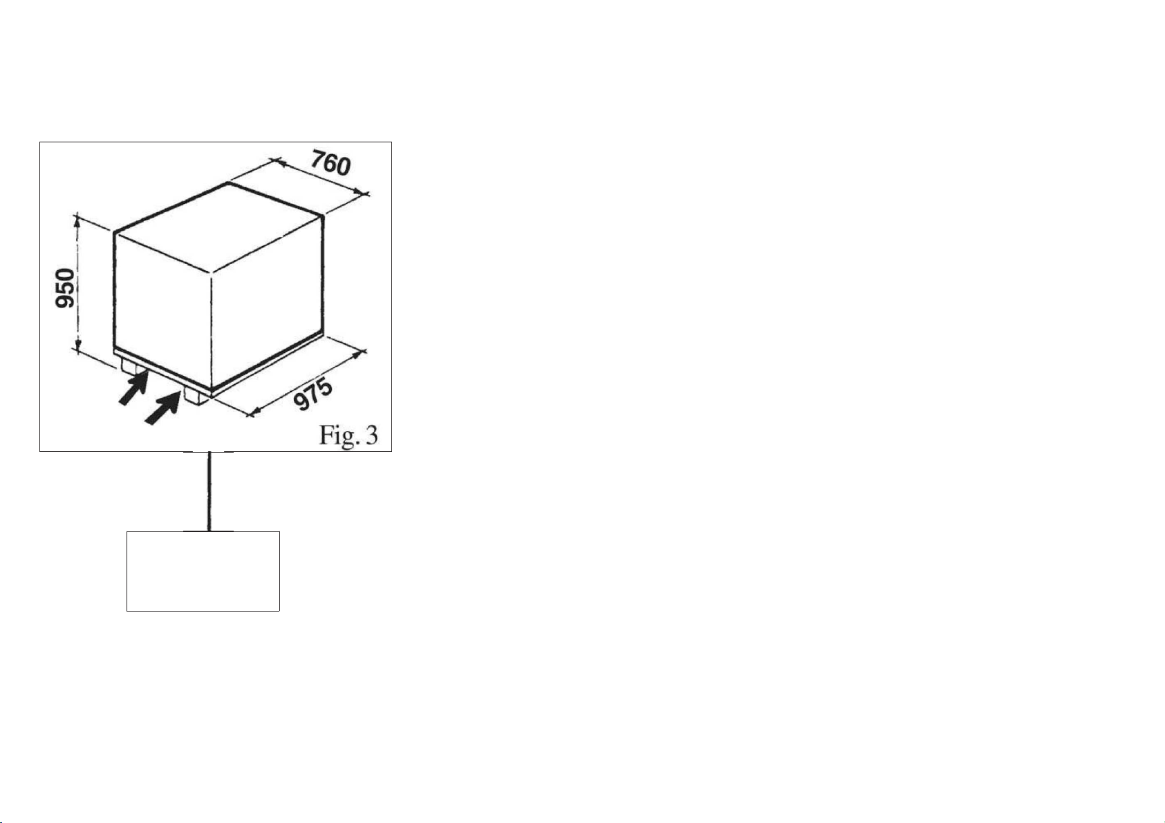
3. TRASPORTO
• Lo smontagomme deve essere trasportato nell'imballo originale e
mantenuto nella posizione indicata sull'imballo stesso.
• Lo spostamento della macchina imballata deve essere effettuato infor-
cando con un carrello elevatore di adeguate capacità, nei punti indicati
dalla figura 3.
4. DISIMBALLO
Togliere il cartone di protezione e il sacchetto in nylon
Assicurarsi dell’integrità dell’apparecchio controllando che non vi siano parti
visibilmente danneggiate o mancanti facendo riferimento alla fig.
In caso di dubbio non utilizzare la macchina e rivolgersi al proprio rivenditore.
2.2 GENERAL SAFETY PRECAUTIONS
The tyre changer may only be used by specially trained and authorized
expert personnel.
• Any tampering or modification to the equipment carried out without the
manufacturer’s prior authorization will free him from all responsibility for
damage caused directly or indirectly by the above actions.
• Removing or tampering with safety devices immediately invalidates
the guarantee and is in contravention of European Safety Standards.
• The tyre changer comes complete with instruction and warning tran-
sfers which are designed to be long-lasting.
If they should for any reason be damaged or destroyed, please ask im-
mediately for replacements from the manufacturer using the codes gi-
ven on page 8.
3. TRANSPORT
• The tyre changer must be transported in its original packaging and
kept in the position shown on the package itself.
• The packaged machine may be moved by means of a fork lift truck of
suitable capacity. Insert the forks at the points shown in figure 3.
4. UNPACKING
Remove the protective cardboard and the nylon bag.
Check that the equipment is in perfect condition, making sure that no
parts are damaged or missing. Use fig. 1 for reference.
If in doubt do not use the machine and contact your retailer.
8
STANDARD :Kg 229
GT:Kg.241+10

2.2 NORMES GENERALES DE SECURITE
L’utilisation du démonte-pneus est permise exclusivement à du person-
nel spécialisé, expressément formé et autorisé.
• Le constructeur n’est pas responsable des dommages causés par les
appareils qui ont été modifiés sans son autorisation préalable.
• La garantie est immédiatement nulle si des modifications ou des tran-
sformations sont apportées aux dispositifs de sécurité; celles-ci sont
une violation des normes européennes pour la sécurité.
• Le démonte-pneus est équipé de décalcomanies d’instructions et d’a-
vis de danger, projetées et réalisées pour durer dans le temps. Si elles
sont endommagées ou détruites, l’utilisateur doit les demander immé-
diatement au constructeur en utilisant les codes de la page 8.
3. TRANSPORT
• Le démonte-pneus doit être transporté dans son emballage et mainte-
nu dans la position indiquée sur l’emballage même.
• La machine emballée doit être déplacée sur les fourches d’un chariot
élévateur d’une capacité appropriée, enfilées aux points indiqués sur la
figure 3.
4. DEBALLAGE
Enlever le carton de protection et le sac en nylon.
Contrôler qu’il n’y ait pas de parties visiblement endommagées ou man-
quantes en se référant à la figure 1.
En cas de doute, ne pas utiliser la machine et s’adresser au revendeur
autorisé.
2.2 ALLGEMEINE SICHERHEITSNORMEN
Die Verwendung des Reifenmontiergerätes ist nur Personen gestattet,
die entsprechende Erfahrung haben, eingewiesen worden und zum Ge-
brauch befugt sind.
- Falls Veränderungen oder Eingriffe auf dem Gerät vorgenommen wer-
den, die vom Hersteller nicht zuvor bewilligt worden sind, haftet
dieser nicht für Schäden, die auf diese zurückzuführen sind.
- Die Entfernung oder Veränderung von Sicherheitsvorrichtungen be-
wirkt den sofortigen Verfall der Garantie und stellt eine Verletzung der
Europäischen Sicherheitsnormen dar.
- Auf dem Reifenmontiergerät wurden Klebeetiketten mit Anweisungen
und Warnungen angebracht, durch deren Beachtung die Lebensdauer
des Gerätes verlängert werden kann.
Werden diese beschädigt oder entfernt, müssen sie sofort beim Hersteller
unter Angabe der Bestell-Nummern von Seite 8 angefordert werden
3. TRANSPORT
Das Reifenmontiergerät darf nur in seiner Originalverpackung und in
der auf der Verpackung angegebenen Position transportiert werden.
Die verpackte Maschine darf nur mit einem dazu geeigneten Gabelsta-
pler angehoben und transportiert werden, wobei die Gabeln an den in
Abb. 3 angegebenen Punkten einzuschieben sind.
4. AUSPACKEN DER MASCHINE
Schutzkarton und Plastikbeutel entfernen.
Kontrollieren, ob das Gerät intakt ist, ob keine sichtbaren Beschädigun-
gen vorhanden sind oder Teile fehlen, siehe dazu Abb.1.
Im Zweifelsfalle die Maschine nicht benützen und den Verkäufer benac-
hrichtigen.
9
5. INSTALLAZIONE
5.1 SPAZIO NECESSARIO
Al momento della scelta del luogo di installazione, è necessario osser-
vare le normative vigenti per
la sicurezza sul lavoro
• Lo smontagomme necessita di collegamenti con la rete elettrica e con
l’impianto di aria compressa.
E’ perciò opportuno installare la macchina in prossimità di tali fonti
energetiche.
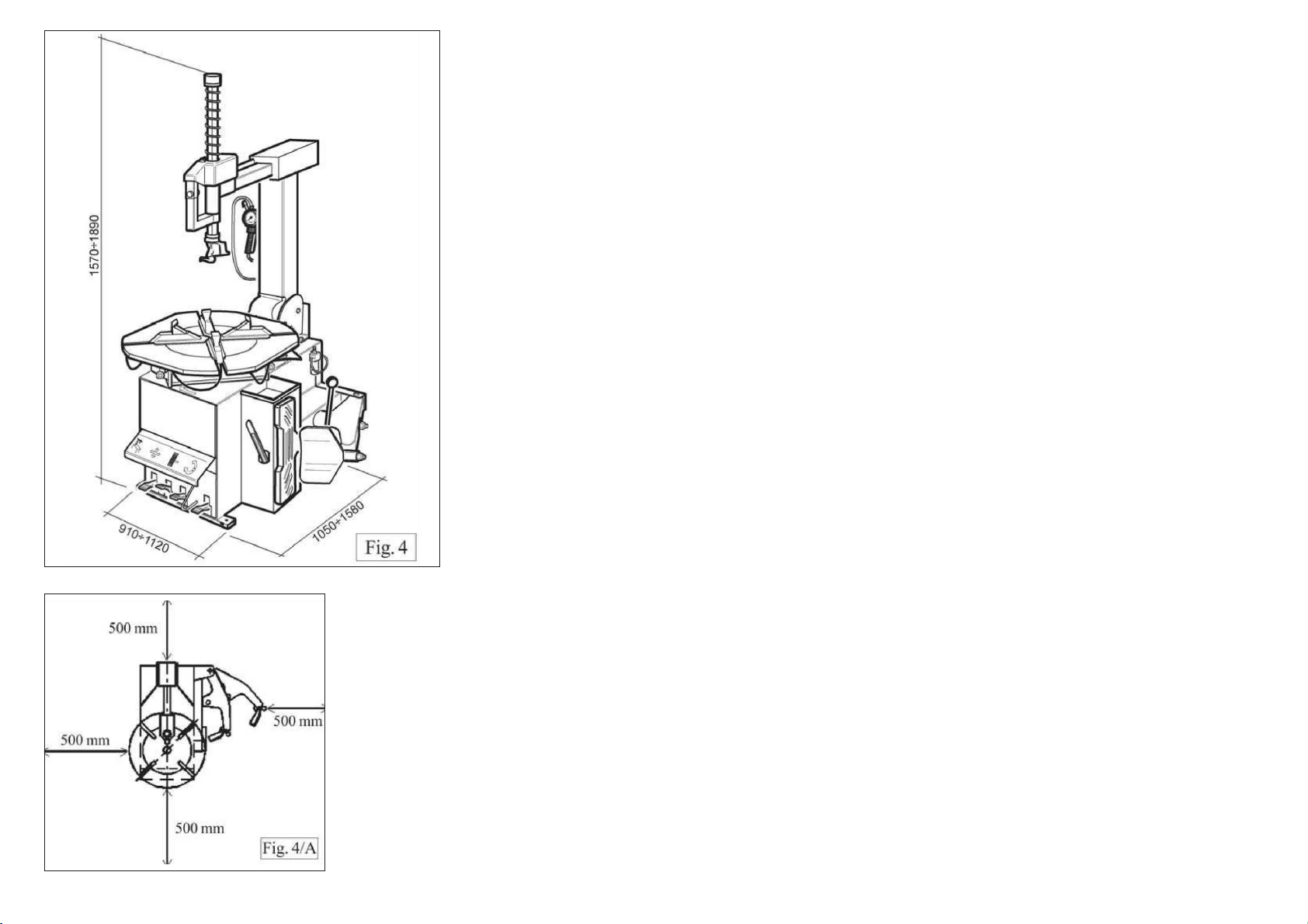
• Inoltre, sul luogo prescelto per l’installazione, devono essere disponi-
bili almeno gli spazi indicati dalle figure 4 - 4/A per
permettere il regolare funzionamento di tutte le sue parti senza alcuna
limitazione.
• Se la macchina viene installata all'aperto è necessario che sia protetta
da una tettoia.
Nel caso lo smontagomme sia del tipo a motore elettrico è proibito l'uso
in atmosfere esplosive a meno che
non si tratti di una apposita versione.
5. INSTALLATION
5.1 SPACE REQUIRED
When choosing the place of installation be sure that it complies with
current safety at work regulations.
•The tyre changer must be connected to the mains electric power
supply and the compressed air system.
It is therefore advisable to install the machine near these power
sources.
•The place of installation must also provide at least the space shown in
pictures 4 - 4/A so as to allow all parts of the machine
to operate correctly and without any restriction.
•If the machine is installed outside it must be protected by a lean-to.
The tyre changer with electric motor cannot be used in explosive atmo-
spheres, unless it is a proper version.
10

5. INSTALLATION
5.1 EMPLACEMENT NECESSAIRE
Au moment du choix du lieu d’installation, observer les normes en vi-
gueur pour la sécurité du travail.
•Le démonte-pneus devra être raccordé au réseau électrique et à l’in-
stallation d’air comprimé.
Il faudra donc en tenir compte pour le choix de l’emplacement.
•De plus, dans le lieu d’installation il faudra les espaces nécessaires
pour permettre le fonctionnement régulier de toutes les parties du
démonte
pneus, sans aucune limitation (voir fig. 4/A).
•Si la machine doit être installée en plein air, elle devra être protégée
par un abri.
Si le démonte-pneus est du type à moteur électrique, son utilisation est
interdite près de matières explosives, à moins qu’il
ne s’agisse d’une version appropriée.
5. INSTALLATION
5.1 PLATZBEDARF
Bei der Wahl des Aufstellungsortes müssen die gültigen Bestimmungen
zur Sicherheit am Arbeitsplatz beachtet werden.
Das automatische Reifenmontiergerät benötigt Anschlüsse an das
Stromnetz und an die Druckluftzufuhr. Deshalb ist es ratsam, die
Maschine
in der Nähe dieser Energiequellen aufzustellen.
Zudem muss am gewählten Installationsort mindestens soviel Platz vor-
handen sein, wie in Abb. 4/A angegeben ist, so daß der Betrieb aller
Maschinenteile problemlos eingestellt werden kann.
Wird die Maschine im Freien aufgestellt, muß sie durch ein Dach
geschützt werden.
Falls das Reifenmontiergerät einen elektrischen Motor aufweist, darf es
nicht in Räumen mit Explosionsgefahr verwendet
werden, außer wenn es um eine geeignete Ausführung handelt.
11
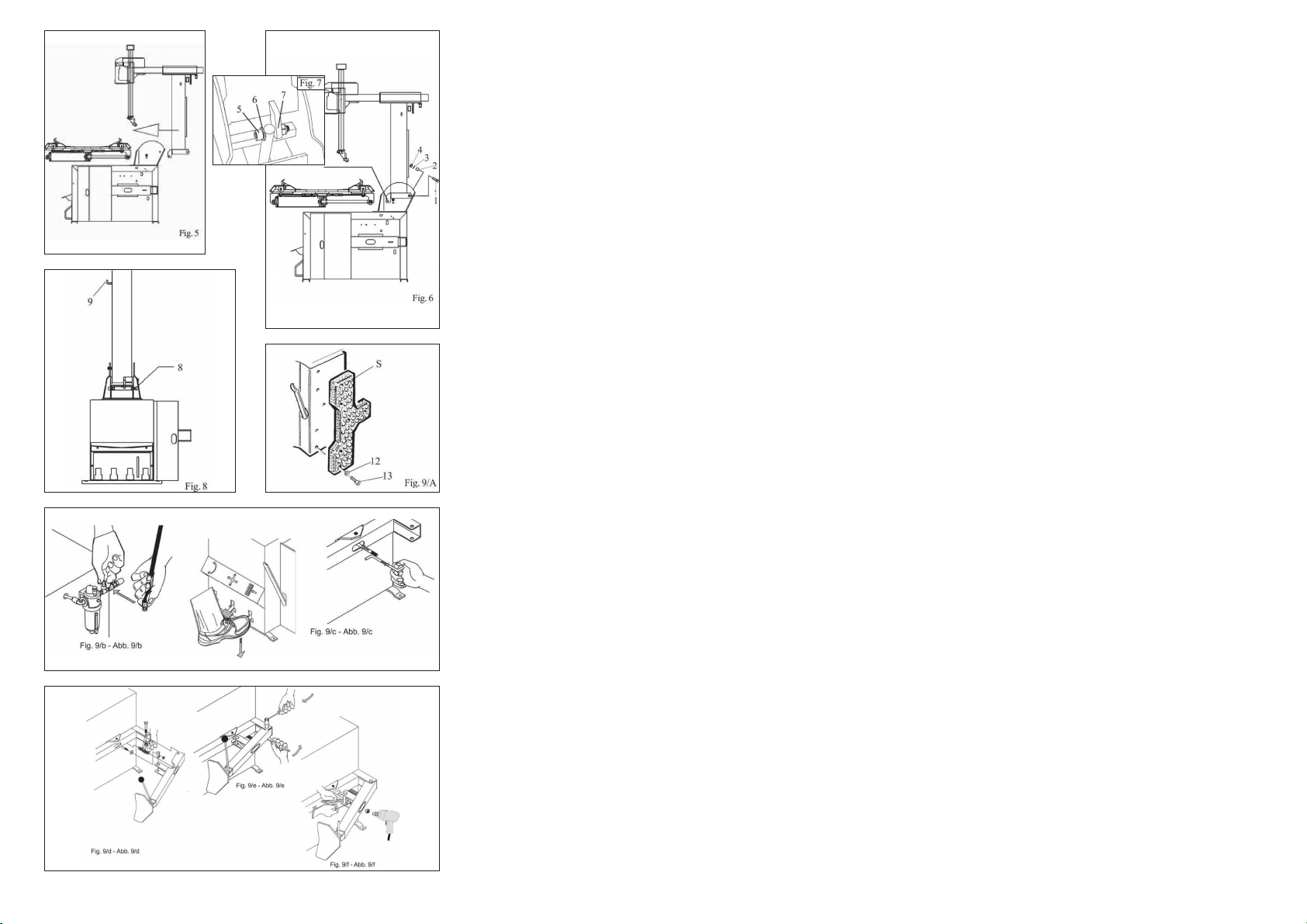
5.2 MONTAGGIO COMPONENTI
5.2.1 Montaggio pali
Inserire il palo verticale nel supporto della carcassa
infilandolo come indicato in fig. 5
Infilare le viti di fulcro posteriori (1), inserire le boccole (2), le
rondelle (3) e serrare i dadi (4). Fig. 6
Infilare il perno (5) comprensivo di rondella (6) per collegare
il cilindro ribaltamento e il palo come indicato in fig. 7
Avvitare il dado (7) avendo cura di non stringere troppo per
permettere al cilindro di poter lavorare correttamente e
ribaltare il palo senza attriti.
Avvitare la vite e la rondella (10) per fissare la carenatura in
plastica come mostrato in Fig. 8.
Montare la paletta stallonatore (R) sul braccio stallonatore,
avendo cura che la rondella (15) resti dalla parte interna del
braccio e la rondella (16) dalla parte esterna.
Bloccare il tutto avvitando il dado autobloccante (17) sul perno
della paletta.
5.2 PARTS ASSEMBLY
5.2.1 Arms assembly
Set the vertical arm into its housing on the machine
body, as shown in picture 5
Set the back screws (1), the bushes (2), the
washers (3) and tighten the nuts (4). Picture 6
Set pin (5) and washer (6) to join the tilting control cylinder to the
arm, as shown in picture 7.
Screw up nut (7) taking care not to tighten too much to enable
cylinder to operate correctly so tilting the arm without frictions.
Tighten screw and washer (10) to fix the plastic cover as shown in
picture 8.
Set the blade (R) on the bead breaker arm taking care to place
washer (15) inside the arm and washer (16) outside.
Lock everything by tightening the self-locking nut (17) on the blade
pin. Fig. 9/A
12

5.2 MONTAGE DES COMPOSANTS
5.2.1 Montage des bras
Insérer le bras vertical dans le logement sur le bâti, comme indiqué en
fig. 5
Insérer les vis arrière (1), les coquilles (2) ainsi que les rondelles (3) et
serrer par les écrous (4). Fig. 6
Insérer l’axe (5) avec rondelle (6) pour brancher le vérin de bascule-
ment au bras, comme indiqué en fig. 7
Visser l’écrou (7) ayant soin de ne pas serrer trop pour permettre au vé-
rin d’opérer correctement et de basculer le bras sans friction.
Visser la vis et la rondelle (10) pour fixer la partie en plastique comme
indiqué en fig. 8.
Installer la palette (R) sur le bras décolleur en faisant attention à posi-
tionner la rondelle (15) à l’intérieur du bras et la rondelle (16) à l’extérie-
ur. Fig. 9
Bloquer le tout en vissant l’écrou de sécurité (17) sur l’axe de la palette.
Fig. 9
5.2 BESTANDTEILENEINBAU
5.2.1 Armeinbau
Den senkrechten Arm in die dazu bestimmte Stütze auf der
Maschinengehäuse einfügen (siehe Abb. 5)
Die hintere Schrauben (1), die Buchsen (2) sowie die
Beilagsscheiben (3) einfügen und die Mutter (4) anziehen. Abb.6
Stift (5) mit Beilagsscheibe (6) einfügen, um den Kippzylinder mit
dem Arm zu verbinden (siehe Abb. 7)
Die Mutter (7) anschrauben aber nicht anziehen, um die korrekte
reibungslose Arbeitsweise Zylinders zu ermöglichen.
Die Schraube und die Beilagsscheibe (10) anziehen, um die
Kunststoffverkleidung zu befestigen. Abb.8
Schaufel (R) auf Wulstabdrückarm einbauen und feststellen, daß
Scheibe (15) auf Innerseite und Scheibe (16) auf Außenseite des
Armes positioniert werden. Fig. 9.
Die selbstsichernde Mutter (17) auf den Schaufelstift anziehen,
um die ganze Gruppe zu befestigen. Fig. 9
13

5.5.2 Montaggio e collegamento serbatoio aria per GT
Fissare il serbatoio sul retro della carcassa con le apposite viti (1)
Smontare il pannello laterale
Fare passare il tubo (2), situato all'interno della carcassa, nel foro posto
sul retro della stessa.
Avvitare il tubo (2) al serbatoio tramite l'apposito raccordo.
5.2.3 Montaggio e collegamento manometro
Fissare la scatola manometro al palo verticale tramite le apposite viti in
dotazione.
Fare passare il tubo di collegamento a spirale nel foro piccolo situato
sul retro della carcassa.
Collegare il tubo rilsan al raccordo del limitatore di pressione posto sul
pedale di gonfiaggio
5.3 MESSA IN SERVIZIO
Prima di effettuare gli allacciamenti, accertarsi che le carat-
teristiche dei propri impianti corrispondano a quelle richie-
ste dalla macchina.
• Se fosse necessario cambiare la tensione di funzionamento della
macchina occorre intervenire sulla morsettiera
(Cap.14 - schema elettrico)
Interventi sull’impianto elettrico, anche se di lieve entità, ri-
chiedono l’intervento di personale professionalmente quali-
ficato.
• Collegare la macchina all’impianto d’aria compressa tramite l’attacco
(Q) sporgente dalla parte posteriore (fig. 12)
• Collegare la macchina alla rete elettrica che deve essere dotata di fu-
sibili di linea, di una buona presa a terra
come da norme vigenti e collegata ad un interruttore automatico di ali-
mentazione (differenziale) tarato a 30 mA.
NOTA: Qualora lo smontagomme venga fornito senza spina elettri-
ca, sarà cura dell'utente montarne una(almeno 16 A) adeguata alla
tensione della macchina e secondo le normative vigenti.
5.2.2 Mounting and connecting the GT-tank
Fix the tank on the back side of the machine body through the proper
screws (1).
Demount the side panel.
Let the hose (2), situated inside the machine body, pass through the
hole on the back side of the body.
Tighten the hose (2) to the tank through the proper union.
5.2.3 Mounting and connecting the manometer
Fix the manometer box to the vertical arm through the proper
screws.
Let the connection spiral hose pass through the small hole on
the back side of the machine body.
Connect the rilsan hose to the union of the pressure limiting
device, situated on the inflating pedal.
5.3 COMMISSIONING
Before making the connections, check that the characte-
ristics of your systems correspond to those required
by the machine.
•If you have to change the machine’s operating voltage, make the ne-
cessary adjustments to the terminal board (Chap.14)
Even small jobs done on the electrical system must be
carried out by professionally qualified personnel.
•Connect the machine to the compressed air system by means of the
air connection (Q) that protrudes from the rear section as shown in the
diagram 12.
•Connect the machine to the electric network, which must be provided with
line fuses, a good earth plate in compliance with regulations in force and it
must be connected to an automatic circuit breaker (differential) set at 30 mA.
Note: Should the tyre-changer be lacking in electric plug, so the
user must set one,which is at least 16 A and which conforms to
the voltage of the machine, in compliance with the regulations in
force.
14

5.2.2 Montage et branchement du réservoir d'air pour GT
Fixer le réservoir sur la partie arrière du bâti moyennant les vis
appropriées (1).
Démonter le panneau lateral.
Laisser passer le tuyau (2), qui se trouve à l'intérieur du bâti, par le trou
arrièr au bâti même.
Visser le tuyau (2) au réservoir moyennant le raccord approprié.
5.2.3 Montage et branchement du manomètre
Fixer la boîte manomètre au bras vertical moyennant les vis fournies.
Laisser passer le tuyau-spirale de connexion par le petit trou qui se
trouve arrière au bâti.
Brancher le tuyau rilsan au raccord du limitateur de pression sur la pé-
dale de gonflage.
5.3 MISE EN MARCHE
Avant d’effectuer les raccordements, vérifier que les ca-
ractéristiques des installations correspondent à celles
demandées par la machine.
•S’il faut changer la tension de fonctionnement de la machine, intervenir
sur le bornier (voir schéma électrique Chap. 14).
Les interventions sur l’installation électrique, même si
elles sont peu importantes, doivent être effectuées par
du personnel qualifié.
•Raccorder la machine à l’installation d’air comprimé par le raccord (Q)
situé à l’arrière (voir figure 12).
•Relier la machine au reseau électrique, qui doit être equipé de fusibles
de ligne et d’une prise de terre conformément aux
normes en vigueur. De plus, il faut relier la machine à un interrupteur
automatique d’alimentation (différentiel) reglé à 30 mA.
NOTE: Si le demonte-pneus est dépourvu de fiche électrique, l’utilisate-
ur devramonter une fiche qui soit proporsionnée à la tension de la ma-
chine ( au moins 16 A) conformément aux normes en vigueur.
5.2.2 Montage und Verbindung von GT-Luftbehälter
Behälter auf Hinterseite der Maschine durch die dazu bestimmten
Schrauben (1) befestigen.
Seitenpanel abmontieren.
Schlauch (2), der sich innerhalb der Maschine findet, durch Loch aur
Hinterseite der Maschine schieben lassen.
Schlauch (2) an der dazu bestimmten Verschraubung befestigen.
5.2.3 Montage und Verbindung des Manometers
Manometergehäuse am Vertikalausleger durch die dazu bestimmten
Schrauben befestigen.
Die Verbindungsspirale durch kleines Loch auf Hinterseite der Maschi-
ne schieben lassen.
Rilsanschlauch mit der Verschraubung der Druckbegrenzvorrichtung
auf dem Aufpumppedal verbinden
5.3 INBETRIEBNAHME
Vor dem Anschluß muß überprüft werden, ob die Eigen-
schaften der Betriebsanlagen den von der Maschine ge-
forderten Werten entsprechen.
-Falls die Betriebsspannung der Maschine geändert werden muß,
entsprechend Schaltplan im Kap. 14 Klemmenbrett vorgehen.
(Auch kleinere)
Eingriffe an der elektrischen Anlage dürfen nur von Fac-
hpersonal vorgenommen werden.
-Maschine an das Druckluftnetz anschließen, hierzu den Anschlußstut-
zen (Q) verwenden, der gemäß Abbildung hinten hervorsteht.
Maschine vorschriftsgemäß an das Stromnetz anschließen. Das Strom-
netz muß mit Schmelzsicherungen sowie mit einem guten Erdschluß
versehen werden. Dazu muß die Maschine an einen selbstätigen 30mA
geeichten Ausschalter (Differential) verbindet werden.
WICHTIG:Wenn das Reifenmontiergerät ohne Steckdose geliefert
wird, muß der Verbraucher mindestens eine 16A Steckdose
anschließen. Diese muß an die Spannung der Maschine angemes-
sen und gemäß der gültigen Bestimmungen sein.
15
5.4 TEST DI FUNZIONAMENTO
• Premendo il pedale (Z) il piatto autocentrante (Y) deve ruotare in sen-
so orario. Spingendo verso l'alto il pedale il piatto autocentrante (Y)
deve ruotare in senso antiorario.
N.B: Se il piatto girasse in senso opposto a quello indicato è ne-
cessario invertire due fili sulla spina trifase
• Premendo il pedale (U) si aziona lo stallonatore (R); rilasciando il pe-
dale lo stallonatore ritorna nella posizione originale
• Premendo il pedale (V) si aprono le quattro griffe di bloccaggio (G);
premendo nuovamente si chiudono.
• Premendo il pedale (H) si ribalta il palo(P); premendo nuovamente il
palo ritorna in posizione di lavoro
• Ponendo il pulsante di bloccaggio (K) in pos.1, si bloccano il braccio
operante(M) ed il braccio orizzontale (N).
La torretta si posiziona automaticamente alla giusta distanza dal
cerchio.
• Premendo il pulsante in pos. 2, i bracci si sbloccano e la torretta scen-
de sul cerchio o fino all'altezza minima di servizio.
• Premendo il pulsante in pos. 3, i bracci si sbloccano e la torretta si
alza in posizione di fuori lavoro
• Premendo il grilletto della pistoletta di gonfiaggio esce aria dalla
testina.
5.4.1 VERSIONE GT
Nell'effettuare questa prova non tenere il viso sopra l'auto-
centrante. Eventuale sporcizia presente sul piatto potrebbe
colpire gli occhi di chi opera. Fare attenzione an che a non
premere accidentalmente il pedale di gonfiaggio durante le
varie fasi di lavoro
• Premendo in posizione intermedia (B) il pedale posto sul lato sinistro
della carcassa, deve uscire aria dalla testina di gonfiaggio.
• Premendo a fondo il pedale (C) esce aria dalla testina e un potente
getto dagli ugelli posti sulle griffe del piatto autocentrante.
5.4 OPERATING TESTS
•When pedal (Z) is pressed down the turntable (Y) should turn in a cloc-
kwise direction.When pedal is pulled up the turntable
should turn in an anticlockwise direction.
Note: If the turntable turns in the opposite direction to that shown,
reverse two of the wires in the three-phase plug.
•Pressing the pedal (U) activates the bead breaker (R); when the pedal
is released the bead breaker returns to its original
position.
•Pressing the pedal (V) opens the four clamps (G) ; when the pedal is
pressed again they close.
•Pressing the pedal (H) tilts the arm (P); when the pedal is pressed aga-
in it returns to its working position.
•Position 1 of the locking button (K) locks the mounting bar (N) and the
horizontal arm (M). The mounting head positions itself automatically at
the correct distance from the rim.
•With the button in Pos.2, the arms are unlocked and the mounting head
goes down onto the rim or until it reaches the minimum working height.
•With the button in Pos.3, the arms are unlocked and the mounting
head goes up to the out-of-work position.
•Pressing the trigger on the airline gauge causes air to be released
from the head.
5.4.1 GT VERSION
Don't lean on the turntable during this operation. Possi-
ble dirty dust on turntable could offend the operator's
eyes. For the same reason, be carefully as not to acci-
dentally push the inflating pedal while working.
• When the pedal located on the left side of the machine body is pushed
down to its intermediate position (B), air is released from the airline gauge.
• When the pedal (C) is pushed down completely, air is released from
the airline gauge along with a powerful jet from the
nozzles located on the turntable clamps.
16
5.4 ESSAIS DE FONCTIONNEMENT
•En appuyant sur la pédale (Z) le plateau (Y) doit tourner dans le sens
horaire.
•En poussant la pédale (Z) vers le haut le plateau (Y) doit tourner dans
le sens anti-horaire.
N.B.Si le plateau tourne dans le sens opposé à celui indiqué, inver-
tir les deux fils sur la fiche triphasée.
•En appuyant sur la pédale (U), le détalonneur (R) se met en marche;
en lâchant la pédale, il retourne à sa position première.
•En appuyant sur la pédale (V), les quatre mors (G) placés sur le plate-
au s’ouvrent; en appuyant de nouveau, ils se ferment.
•En appuyant sur la pédale (H), le bras (P) bascule; en appuyant de no-
uveau, le bras revient à sa position de travail.
•En positionnant le bouton de blocage (K) en position 1, le bras opéra-
teur (M) et le bras horizontal (N) se bloquent.
La tête de montage se déplace automatiquement jusqu'à la juste di-
stance de la jante.
•En positionnant le bouton de blocage (K) en position 2, le bras se dé-
bloquent
•En appuyant sur la détente du pistolet de gonflage, l’air sort.
5.4.1 VERSION GT
Lors de cet essai ne pas mettre le visage au-dessus du pla-
teau autocentreur. La saleté qui se trouve sur le plateau au-
tocentreur pourrait blesser les de l'operateur. Pour cette rai-
son faire attention à ne pas appuyer accidentellement sur la
pédale de gonflage pendant les opération.
• En appuyant sur la pédale placée sur le côté gauche du bâti dans la
position intermédiaire (B), de l’air doit sortir du pistolet de gonflage.
• En appuyant à fond sur la pédale (C), de l’air sort du pistolet de gon-
flage et un jet puissant sort par les gicleurs placés sur les mors du pla-
teau tournant.
5.4 FUNKTIONSTEST
-Pedal (Z) drücken; der Zentriertisch (Y) dreht sich im Uhrzeigersinn.
-Wird das Pedal (Z) nach oben gedrückt, sodreht sich der Zentriertisch
(Y) im Gegenuhrzeigersinn.
Wichtig! Falls sich der Zentriertisch in der falschen Richtung
dreht, zwei Drähte auf dem Dreiphasenstecker umpolen.
-Durch Pedaldruck (U) wird das Abdrückblatt (R) betätigt, das Pedal fre-
igegeben, kehrt das Abdrückblatt in seine Ausgangsstellungzurück.
-Durch Pedaldruck (V) öffnen sich die vier Spannklauen (G) auf dem
Zentriertisch. Auf erneutem Druck schließen sie sich.
- Durch Pedaldruck (H) kippt der Arm (P). Auf erneutem Druck kehrt er
in die Arbeitsposition zurück.
- Mit Sperrdrucktaste (K) in Position 1 werden der Werkzeugarm (M)
und der Stützarm (N) blockiert. Der Montierfuß positioniert sich automa-
tisch auf den richtigen Abstand von Felge.
- Mit Sperrdrucktaste (K) in Position 2 werden die Arme freigegeben.
-Auf Druck des Abzugs der Druckluftpistole tritt Luft aus dem Scher-
kopf.
5.4.1 GT-AUSFÜHRUNG
Beim Ausfüren dieser Prüfung das Gesicht das Gesicht
auf keinen Fall über den Spanntisch halten. Eventuell
auf dem Spanntisch vorhandener Schmutz könnte sonst
dem Bediener in die Augen fliegen. Aus dem gleichen
Grund darauf achten, daß man während der Arbeit nie
aus Versehen auf das Reifenfüllpedal tritt.
-Bei Druck des Pedals an der linken Gehäuseseite in die Mittelstellung
(B) muß Luft aus dem Reifenfülldrückgerät strömen.
-Wird das Pedal (C) ganz gedrückt, so strömt Luft aus dem Rei-
fenfülldruckgerät, und ein starker Luftstrom aus den Düsen, die sich an
denn Spannklauen des Zentriertisches befinden.
17

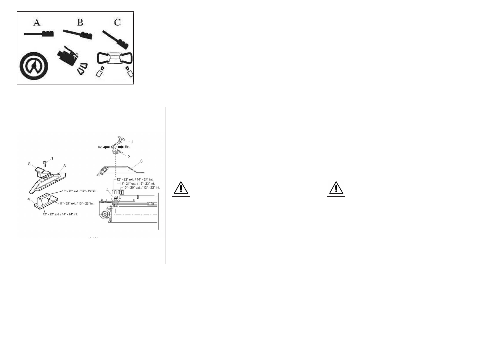
5.5 REGOLAZIONE MISURE DI BLOCCAGGIO PIATTO
AUTOCENTRANTE
Il piatto autocentrante dello smontagomme viene regolato dal costruttore su
una misura di bloccaggio intermedia che va da 11" a 21" ext (rispetto all'e-
sterno del cerchio) e da 13" a 23" int. (se si blocca il cerchio dalla parte inter-
na). E' pero' possibile modificare tali valori qualora si debba operare su cer-
chi di dimensioni minori o maggiori spostando la posizione delle 4 griffe
come indicato nelle figure sottostanti.
Il range di valori ottenibili in questo modo varia da un minimo di 10"-20"
ext. e 12-22" int. ad un massimo di 12"-22" ext e 14"-24" int.
Per modificare la posizione:
Svitare la vite (1) per mezzo di una chiave a brugola
Rimuovere la griffa di bloccaggio (2) e lo scorrevole (3)
Posizionare il foro dello scorrevole in corrispondenza di quello della gui-
da (4) a seconda delle dimensioni di bloccaggio che si vogliono
ottenere. Fare riferimento alle misure riportate sotto.
Riposizionare la griffa e bloccare tramite la vite (1) avendo cura di con-
trollare la coppia di serraggio che deve essere 72 Nm.
I
ATTENZIONE
: e’ importante che le operazioni suddette vengano effettuate in egual
maniera su tutte le 4 griffe di serraggio per evitare scompensi in fase di
bloccaggio.
6. USO
Non utilizzare la macchina prima di aver letto e capito
tutto il manuale e gli avvertimenti in esso riportati.
L’uso dello smontagomme si suddivide in tre parti:
a) STALLONATURA b)SMONTAGGIO DEL PNEUMATICO
c)MONTAGGIO DEL PNEUMATICO
Prima di qualsiasi operazione è necessario sgonfiare il
pneumatico e togliere tutti i contrappesi di
equilibratura
Note sull’utilizzo:
I cerchi delle moto sono sempre piu’ frequentemente costruiti con leghe
speciali o materiali come il carbonio o il magnesio.
Per bloccare questi tipi di cerchio occorre utilizzare il kit attacchi per ru-
ote moto cod 2008632 e limitare la pressione esercitata dal piatto auto-
centrante ad un massimo di 5 bar.
In questo modo si evita di danneggiarli o deformarli in modo irreparabile.
Qualora il Vs. smontagomme fosse sprovvisto di regolatore di pressio-
ne, per limitare la pressione di esercizio e’ consigliabile installare l’ap-
posito kit cod. 2011215.
5.5 TURNTABLE LOCKING VALUE ADJUSTING
The tyre-changer turntable is preset by the manufacturer on a middle
range measure from 11" to 21" ext. (considering the rim outer side)
and from 13" to 23" int. (if you lock the rim from inner side).
It is however possible to change this dimension range in case of need
when working on larger or smaller rims; it is enough to change the
position of the 4 clamps as shown in the figures below.
The obtainable value scales start from a minimum of 10"-20" ext. and
12"-22" int. until a maximum of 12"-22" ext. and 14"-24" int.
To change the position proceed as follows:
Unscrew screw (1) by means of the Allen wrench
Remove the locking clamp (2) and the slide piece (3)
Let the slide hole coincide with one of the guide holes (4) according to
the locking dimensions you want to set. Use the measures below
for reference.
Set the clamp again and fasten it by means of screw (1) paying atten-
tion to the torque wrench setting which must be 72 Nm.
I
ATTENTION:
it is important to perform the above mentioned operation for all the 4
clamps to avoid any unbalance in ocking phase.
6.OPERATION
Do not use the machine until you have read and under-
stood the entire manual and the warnings it provides.
The operation of the tyre changer is divided into three parts:
a) BREAKING THE BEAD b) REMOVING THE TYRE c) MOUNTING THE
TYRE
Before carrying out any operation, deflate the tyre and
take off all the wheel balancing weights.
Note for use:
The motorcycle rims are more and more frequently constructed by
using special alloys or materials like carbon or magnesium.
To lock this kind of rims it is necessary to use the motorcycle wheels
adaptors kit, code nr. 2008632 and to limit the pressure exerted by tur-
ntable to 5 bar max., in order to avoid any irreparable damage of
deformation.
If your tyre-changer is not equipped with pressure regulator, it is advi-
sed to add the kit having code nr. 2011215
18
Table of contents
Other WERTHER INTERNATIONAL Tyre Changer manuals


Popular Tyre Changer manuals by other brands

GIULIANO
GIULIANO G1 SPORT Operation instructions

GIULIANO
GIULIANO S 551 XL A Use and maintenance instructions

Atlas Equipment
Atlas Equipment Atlas TC221 Assembly guide

Z.I.P.P.ER MASCHINEN
Z.I.P.P.ER MASCHINEN ZI-RMM95 user manual

GIULIANO
GIULIANO S 557 Use and maintenance instructions

HENNESSY INDUSTRIES
HENNESSY INDUSTRIES coats AMMCO RC-45 A coats AMMCO RC-45 E manual


GIULIANO
GIULIANO S 560 Use and maintenance instructions

Weber
Weber Expert Series manual

Cormach
Cormach CM SUPER 27 Use and maintenance manual

Ranger
Ranger R80EX Installation and operation manual

ATEK MAKINA
ATEK MAKINA POLISH-CLN Instruction booklet

Coats
Coats CHD-9041 Operating and maintenance instructions