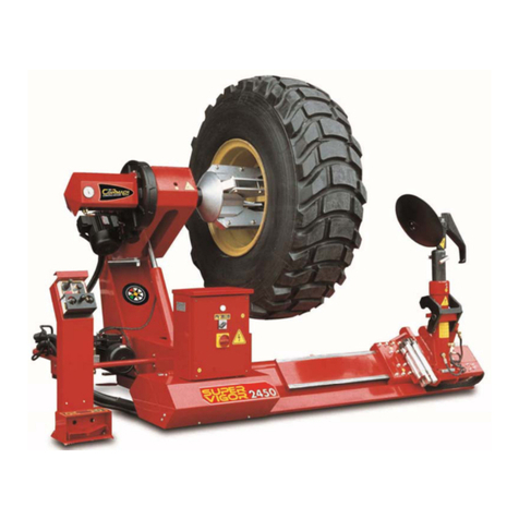
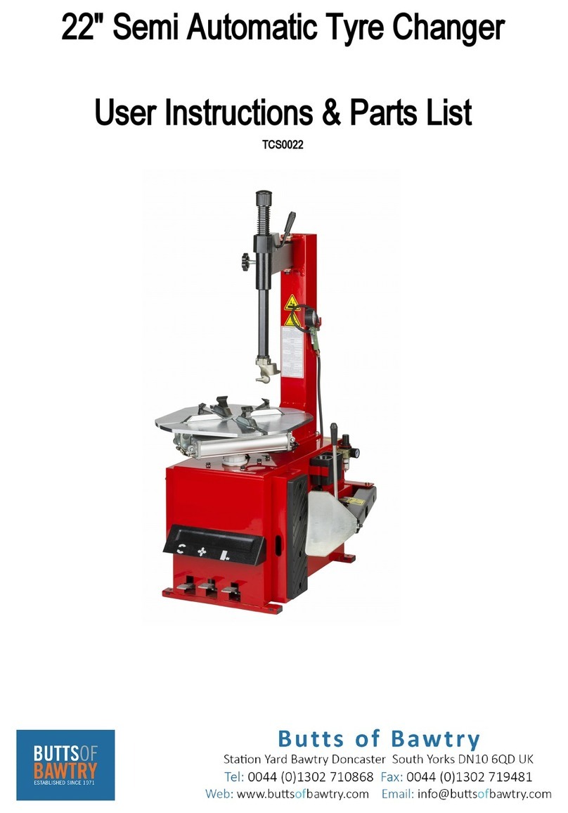
Cormach CM SUPER 27 User manual

SMONTAGOMME
TYRE CHANGER
DEMONTE-PENUS
REIFENMONTIERMASCHINE
DESMONTADORA
CM SUPER 27
09/2002
MANUALE USO E MANUTENZIONE
USE AND MAINTENANCE MANUAL
MANUEL D’UTILISATION ED D’ENTRETIEN
HANDBUCH FÜR GEBRAUCH UND WARTUNG
MANUAL DE USO Y MANTENIMIENTO
IT
UK
FR
D
ES

Universal truck tyre changer
2002/96/CE 2003/108/CE (RAEE)
DICHIARAZIONE DI CONFORMITA' RoHS
RoHS DECLARATION OF CONFORMITY
DECLARATION DE CONFORMITE RoHS
RoHS - ÜBEREINSTIMMUNG
Nota:
Remarks:
Note:
Anm.:
CORMACHS.r.l.-ViaMons.Pignedoli,2-
42015Correggio(RE)ITALY
2002/95/CE (RoHS)

2002/96/CE e 2003/108/CE (RAEE)
DICHIARAZIONE DI CONFORMITA' RAEE
RAEE DECLARATION OF CONFORMITY
DECLARATION DE CONFORMITE RAEE
RAEE - ÜBEREINSTIMMUNG
Universal truck tyre changer
CORMACHS.r.l.-ViaMons.Pignedoli,2-
42015Correggio(RE)ITALY

SOMMARIO
INDEX
SOMMAIRE
INHALT
INDICE
1 - GENERAL INFORMATION
2 - TECHNICAL DATA
3 - GENERAL SAFETY REGULATION
4 - SAFETY DEVICES
5 - TRANSPORT
6 - UNPACKING
7 - INSTALLATION
7.1 Installation place
7.2 Workplace requirements
7.3 Electric hook up
Sense of rotation check
8 - LAYOUT OF FUNCTIONAL PARTS
9 - IDENTIFYING WARNING SIGNALS
10 - IDENTIFICATION OF CONTROL
11- WORKING POSITION
12 - CORRECT OPERATION CHECKS
13 - OPERATION
13.1 Locking the wheel
Light-alloy rim locking
13.2 Tubeless and supersingle wheels
Bead breaking
Demounting
Mounting
13.3 Tubed wheels
Bead breaking
Demounting
Mounting
13.4 Wheels with split ring
Bead breaking and demounting
Mounting
14 - ORDINARY MAINTENANCE
15 - TROUBLE SHOOTING
16- MOVING THE MACHINE
17- STORING
18- SCRAPPING A MACHINE
19- DATA ON SERIAL PLATE
20- ACCESSORIES
1 - GENERALITA'
2 - CARATTERISTICHE TECNICHE
3 - NORME DI SICUREZZA
4 - DISPOSITIVI DI SICUREZZA
5 - TRASPORTO
6 - DISIMBALLO
7 - INSTALLAZIONE
7.1 Luogo di installazione
7.2 Posizionamento
7.3 Allacciamento elettrico
Controllo senso rotazione
8-RAPPRES.DELLEPARTIFUNZIONALI
9 - IDENTIFIC. SEGNALI DI PERICOLO
10 - IDENDIFICAZIONE DEI COMANDI
11 - POSIZIONE DI LAVORO
12 - CONTROLLO CORRETTO FUNZION.
13 - USO
13.1 Bloccaggio ruota
Bloccaggio cerchi in lega
13.2 Ruote tubeless e supersingle
Stallonatura
Smontaggio
Montaggio
13.3 Ruote con camera d'aria
Stallonatura
Smontaggio
Montaggio
13.4 Ruote con cerchietto
Stallonatura e smontaggio
Montaggio
14 - MANUTENZIONE ORDINARIA
15 - INCONVENIENTI/CAUSE/RIMEDI
16-MOVIMENTAZIONE
17-ACCANTONAMENTO
18-ROTTAMAZIONE
19-DATI DI TARGA
20- ACCESSORI
1 - GENERALITES
2 - CARACTERIST. TECHNIQUES
3 - NORMES DE SECURITE
4 - DISPOSITIFS DE SECURITE
5 - TRANSPORT
6 - DEBALLAGE
7 - INSTALLATION
7.1 Lieu d’installation
7.2 Mise en place
7.3 Raccordement électrique
Contrôle du sens de rotation
8 - REPRES. DES PIECES FONCIONNELLES
9 - IDENTIFIC. DES SIGNAUX DE DANGER
10 - IDENTIFICATION DES COMMANDES
11 - POSITION DE TRAVAIL
12 - CONTROLE DU BON FONCTIONN.
13 - UTILISATION
13.1 Blocage de la roue
Blocage des jantes en alliage
13.2 Roues tubeless et supersingle
Détalonnage
Démontage
Montage
13.3 Roues à chambre à air
Détalonnage
Démontage
Montage
13.4 Roues avec cercle
Détalonnage et démontage
Montage
14 - ENTRETIEN ORDINAIRE
15 - INCONV./CAUSES/REMEDES
16 - MANUTENTION
17 - REMISAGE
18 - MISE A DECHARGE
19 - PLAQUE SIGNALETIQUE
20 - ACCESSOIRES
1 - ALLGEMEINES
2 - TECHNISCHE DATEN
3 - SICHERHEITSBESTIMMUNGEN
4 - SICHERHEITSVORRICHTUNGEN
5 - TRANSPORT
6 - AUSPACKEN
7 - INSTALLATION
7.1 Standort
7.2 Aufstellung
7.3 Elektrischer Anschluß
Kontrolle der Drehrichtung
8 - DARSTELLUNG DER WICHTIGSTEN
MASCHINENTEILE
9 - KENNZEICHNUNG DER WARNSIGNALE
10- KENNZEICHNUNG DER BEDIENUNGSEL.
11 - ARBEITSPOSITION
12-PRÜFUNGAUFKORREKTEN BETRIEB
13 - BENUTZUNG
13.1 Radaufspannen
Aufspannen von Alu-Felgen
13.2 Schlauchlose und Supersingle-Räder
Abdrücken
Demontage
Montage
13.3 Schlauchräder
Abdrücken
Demontage
Montage
13.4 Räder mit Spaltring
Abdrücken und Demontage
Montage
14 - WARTUNG
15 - FEHLERSUCHE
16 - BEWEGEN
17 - LAGERHALTUNG
18 - VERSCHROTTEN
19 - DATEN DES TYPENSCHILDS
20 - ZUBEHÖR
1 - GENERALIDADES
2 - CARACTERISTICAS TECNICAS
3 - NORMAS DE SECURIDAD
4 - DISPOSITIVOS DE SECURIDAD
5 - TRANSPORTE
6 - DESEMBALAJE
7 - INSTALACION
7.1 Lugar de instalación
7.2 Colocación de la máquina
7.3 Conexión eléctrica
Control de sentido de giro
8- REPRES. DE LAS PARTESFUNCIONALES
9 - IDENTIF. DE SENALES DE PELIGRO
10 - IDENDIFICACION DE COMANDOS
11 - POSICION DE TRABAJO
12 - CONTROL DEL CORRECTO FUNCION.
13 - UTILIZACION
13.1 Bloqueo de la rueda
Bloqueo llantas de aleación
13.2 Ruedas tubeless y supersingle
Destalonado
Desmontaje
Montaje
13.3 Ruedas con cámara de aire
Destalonado
Desmontaje
Montaje
13.4 Ruedas con arillo
Destalonado y desmontaje
Montaje
14 - MANTENIMIENTO ORDINARIO
15 -
PROBLEMAS/CAUSAS/SOLUCIONES
16 - TRASLADO
17 - ALMACENADO
18 - DESGUACE
19 - DATOS DE MATRICULA
20 - ACCESORIOS
4/5
4/5
4/5
6/7
6/7
8/9
8/9
8/9
8/9
10/11
10/11
12/13
14/15
16/17
16/17
16/17
20/21
20/21
22/23
22/23
22/23
26/27
28/29
34/35
34/35
34/35
36/37
42/43
42/43
46/47
52/53
54/55
56/57
56/57
56/57
58/59
58/59

4
Pump motor
Gear-box motor
Handles rim from
Max. wheel diameter
Max. wheel width
Max. wheel weight
Weight (with standard accessories)
Acoustic pressure level (at work)
1,1 kw
1,3 / 1,8 kw
14" - 56"
1.600 mm
780 mm
1500 kg
560 Kg
LpA <70 dB (A)
1,1 kw
1,3 / 1,8 kw
14" - 56"
1.600 mm
780 mm
1500 kg
560 kg
LpA <70 dB (A)
GENERALITA'
1
GENERALINFORMATION
1
Questo smontagomme è una macchina realizzata per smontare e
montare pneumatici di autocarri, autobus e veicoli industriali con
cerchi da 13" a 27" e diametro max.1.600 mm.
Qualsiasi altro utilizzo è da ritenersi improprio e quindi irragionevole
e non consentito.
Prima di iniziare qualsiasi tipo di operazione è INDISPENSABILE
leggere e capire quanto riportato su queste istruzioni.
Il Costruttore non può essere ritenuta responsabile di danni causati
dall'uso improprio ed irragionevole delle sue attrezzature.
CONSERVARE CON CURA QUESTO MANUALE PER OGNI
ULTERIORE CONSULTAZIONE.
This tyre changer has been specifically designed to demount and
mount truck, bus and commercial van tyres, with rims from 13" to
27" and a maximum 1.600 mm diameter.
Any other use is improper and therefore not authorized. Before be-
ginning any kind of work on or with this machine, carefully read and
understand the contents of these operating instructions.
The Manufacturer shall not liable for any injury to persons or dam-
age to things caused by improper use of this machine.
KEEP THIS MANUAL NEAR THE MACHINE AND CONSULT IT AS
NEEDED DURING OPERATIONS.
Any work, however minor, on the electric
system must be done exclusively by
professionally qualified personnel.
NORMEGENERALIDISICUREZZA
3
L'uso dell'apparecchiatura è consentito solo a personale ap-
positamente addestrato ed autorizzato.
Qualsiasi manomissione o modifica dell'apparecchiatura non
preventivamente autorizzate dal costruttore sollevano quest'ul-
timo dai danni causati o riferibili agli atti suddetti.
La rimozione o manomissione dei dispositivi di sicurezza com-
porta una violazione delle norme europee.
Interventi sull'impianto elettrico, anche di
lieve entità, richiedono l'opera di
personale professionalmente qualificato.
2
CARATTERISTICHETECNICHE
Motore pompa
Motore riduttore
Opera su ruote da
Diametro max. ruota
Larghezza max. ruota
Peso max. ruota
Peso (con accessori in dotazione)
Livello di press. acustica al posto di lavoro
2
TECHNICALDATA
3
GENERALSAFETYREGULATIONS
The use of this machine is reserved to specially trained and author-
ized personnel.
Any unauthorized changes or modifications to the machine, in par-
ticular to its electric system, relieve the manifacturer from all liability.
Removing or tampering with the safety devices installed on this
machine is in violation of European Safety Regulations.

5
1,1 kw
1,3 / 1,8 kw
14" - 56"
1.600 mm
780 mm
1500 kg
560 Kg
NpA <70 dB (A)
Pumpenmotor
Getriebemotor
Spannbereich
Max. Raddurchmesser
Max. Radbreite
Max. Radgewicht
Gewicht (mit Standardzubehör)
Schalldruckpegel am Arbeitsplatz
Moteur pompe
Moteur réducteur
Travaille sur des roues de
Diamètre maxi. de la roue
Largeur maxi. de la roue
Poids maxi. de la roue
Poids (avec accessoires standard)
Niveau sonore au poste de travail
1,1 kw
1,3 / 1,8 kw
14" - 56"
1.600 mm
780 mm
1500 kg
560 Kg
LpA <70 dB (A)
1,1 kw
1,3 / 1,8 kw
14" - 56"
1.600 mm
780 mm
1500 kg
560 Kg
LpA <70 dB (A)
ALLGEMEINES
1
Diese Montiermaschine eignet sich zum Demontieren und Montieren
von LKW-, Bus- und Nutzfahrzeug-Reifen mit Felgen von 13" bis
27" und einem Durchmesser bis zu 1.600 mm.
Jede andere Verwendung ist als nicht vom Hersteller vorgesehen
zu betrachten und daher verboten.
Bevor man irgendeine Arbeit mit der Maschine beginnt, ist es
UNBEDINGT erforderlich, diese Anleitung durchzulesen und ihren
Inhalt zu verstehen.
Der Hersteller haftet nicht für Schäden, die durch die nicht
vorgesehene und unvernünftige Benutzung ihrer Geräte entstehen.
DIESES HANDBUCH SORGFÄLTIG AUFBEWAHREN, UM BEI
BEDARF STETS DARIN NACHSCHLAGEN ZU KÖNNEN.
GENERALIDADES
1
Esta desmontadora es una máquina realizada para desmontar y
montar neumáticos de camión y vehículos industriales con llantas
de 13" a 27" y diámetro máximo de 1.600 mm.
Cualquier otro uso es impropio y por tanto irracional y no permitido.
Antes de comenzar cualquier tipo de operación es indispensable
leer y comprender cuanto muestra estas instrucciones.
El fabricante no puede ser considerado responsable de daños
causados por el uso impropio e irracional de sus equipos.
CONSERVAR CON CUIDADO ESTE MANUAL PARA CUALQUIER
CONSULTA ULTERIOR
Cualquier intervención en el equipo eléctrico,
aunque sea de carácter sencillo, precisa la
intervención de personal profesionalmente
cualificado.
Die Maschine darf nur von Personal benutzt werden, das speziell
angeleitet wurde und dazu eine Genehmigung hat.
Jede Umrüstung oder Änderung der Maschine, die vorher nicht
vom Hersteller genehmigt worden ist, befreit diesen von der
Haftung für etwaige Folgeschäden.
Die Entfernung oder der Aufbruch der Sicherheitsvorrichtungen
stellt eine Verletzung der europäischen Normen dar.
SICHERHEITSBESTIMMUNGEN
3
2
TECHNISCHEDATEN
Alle Arbeiten an der elektrischen Anlage, auch
kleineren Umfangs, dürfen nur von
entsprech-end geschultem und qualifizier-
tem Personal vorgenommen werden.
NORMASDESEGURIDAD
3
El uso del equipo está permitido solo a personal adiestrado a
propósito y autorizado.
Cualquier intervención o modificación del interior del equipo
que no esté previamente autorizada por el fabricante libra a
este último de los daños causados o referibles por tal acción.
La degradación o manipulación de los dispositivos de
seguridad comporta una violación de las normas europeas.
2
CARACTERISTICASTECNICAS
Motor bomba
Motor reductora
Trabaja con ruedas de:
Diámetro máximo de rueda
Ancho máximo de rueda
Peso máximo de la rueda
Peso (con accesorios en dotación)
Nivel de presión acústica en el puesto de trabajo
GENERALITES
1
Cette machine a été réalisée pour démonter et monter des
pneumatiques de camions, autobus et de véhicules industriels avec
des jantes de 13" à 27" et un diamètre max. de 1.600 mm.
Toute autre utilisation est considérée impropre et par conséquent
non autorisée.
Avant de commencer tout type d’opération il est INDISPENSABLE
de lire et de comprendre ce qui est indiqué dans cette notice.
Le Constructeur ne sera pas responsable des dégâts causés par
une utilisation impropre de ses équipements.
CONSERVER SOIGNEUSEMENT CE MANUEL POUR TOUTE
CONSULTATION ULTERIEURE.
Les interventions sur le circuit électrique, même
de faible importance, doivent être
réalisées par du personnel spécialisé.
2
CARACTERISTIQUESTECHNIQUES
NORMESGENERALESDESECURITE
3
L’utilisation de l’appareillage est réservée au personnel
spécialement formé et autorisé.
Toute manipulation ou modification de l’appareillage sans
autorisation préalable du constructeur décharge ce dernier
dans le cas de dommages attribuables à ces actes.
La dépose ou la manipulation des dispositifs de sécurité est
une violation des normes européennes.

6
DISPOSITIVI DI SICUREZZA
4
4
SAFETY DEVICES
The tyre changer has a number of safety devices designed to guar-
antee the utmost operator safety:
1. Check valve on the spindle opening hydraulic line (inside the
swivel connector, see fig. B/1). This prevents the wheel from falling
from the spindle if the hydraulic line is accidentally broken.
2. Pressure relief valve factory set at 130 bar ±5% (See Fig. B/2).
This limits the pressure in the hydraulic circuit and ensure correct
operation of the plant.
3. Pump motor overload cut-out (inside the electric enclosure).
This cuts in if the motor overheats to prevent it from burning out.
CAUTION!
Removing or tampering with safeties is in violation of European
Safety Regulations and relieves manufacturer of any and all li-
ability for injury to persons to damage to things caused or refer-
able to such acts.
Lo smontagomme è dotato di una serie di dispositivi preposti a
garantire la massima sicurezza per l'operatore :
1) Valvola di non ritorno sulla linea di apertura dell'autocentrante
(situata all'interno del raccordo girevole, vedi Fig. B/1).Evita una
possibile caduta della ruota dovuta ad accidentali rotture del circui-
to oleodinamico.
2) Valvola di massima pressione - tarata a 130 Bar ±5%-
(vedi Fig. B/2).
Limita la massima pressione sul circuito oleodinamico salvaguar-
dando il buon funzionamento dell'impianto.
3) Interruttore magnetotermico di protezione del motore pompa
(situato all'interno della centralina elettrica). Interviene in caso di
surriscaldamento del motore evitandone la bruciatura.
ATTENZIONE: La rimozione o manomissione dei dispositivi di si-
curezza comporta una violazione delle norme europee e solleva il
costruttore dai danni causati o riferibili agli atti suddetti.
TRASPORTO
5
La macchina viene fornita, secondo richiesta del cliente in tre
diverse versioni:
1- in cassa di legno con pallet
2- fissata sul solo pallet
3- senza imballo
Nella prima e nella seconda versione deve essere movimentata per
mezzo di un fork-lift posizionando le lame nei punti indicati in
Fig. A/2.
Per le altre versioni seguire le indicazioni del paragrafo
"MOVIMENTAZIONE" riportate a pag. 56 di questo manuale.
Il peso della macchina imballata è di 600 Kg.
TRANSPORT
5
Depending on customer request, the machine is delivered in 3 pack-
ing versions:
1- in a wooden crate with pallet
2- fixed to a pallet
3- no packing
In the first and second case, the machine must be handled with a
fork-lift truck with the forks positioned as shown in the figure A/2.
For the other versions, follow the “Handling” instructions given on
page 56 of this manual.
Shipping weight for the machine is 600 kg.
KG. 600
B/2
B/1
A/2

7
4
SICHERHEITSVORRICHTUNGEN
Die Reifenmontiermaschine ist mit einer Reihe von
Sicherheitsvorrichtungen ausgerüstet, die dem Bediener ein
Höchstmaß an Sicherheit garantieren:
1) Rückschlagventil auf der hydraulischen Leitung zum Öffnen
des Spannfutters (innerhalb des Drehanschlusses angebracht, vgl.
Abb. B/1). Es vermeidet das Fallen des Rades infolge von Brüchen
der hydraulischen Leitung.
2) Überdruckventil - eingestellt auf 130 bar ± 5% (vgl. Abb. B/2).
Beschränkt des Höchstdruck der hydraulischen Leitung, um den
ordnungsgemäßen Betrieb der Anlage zu gewährleisten.
3) Motorschutzschalter für den Pumpenmotor (befindet sich im
elektrischen Kasten). Spricht an, wenn der Motor warm läuft, und
verhindert, daß er durchbrennt.
ACHTUNG: Die Entfernung oder Verstellung der
Sicherheitsvorrichtungen entspricht einer Verletzung der
europäischen Normen und enthebt den Hersteller von der Haftung
für alle Folgeschäden.
DISPOSITIVOS DE SECURIDAD
4
La desmontadora está dotada de una serie de dispositivos
aptos para garantizar la maxima securidad para los operarios:
1) Válvula de antiretorno en la línea de apertura del autocentrante
(situada en el interior del racor giratorio, ver Fig. B/1). Evita una
posible caída de la rueda debida a accidentales roturas del circuito
oleodinámico.
2) Válvula de sobrepresión tarada a 130 Bar ±5% (ver Fig. B/2).
Limita la máxima presión en el circuito hidráulico asegurando el
bueno funcionamiento del circuito.
3) Interruptor magnetotérmico para proteccion del motor de bom-
ba (situado en el interior de la centralina eléctrica).
Interviene en el caso de sobrecalentamiento del motor evitando que
su quemado.
ATENCION: La degradación o manipulación de los dispositivos
de seguridad comporta una violación de las normas europeas y
libera al constructor de los daños causados o referibles a los
actos citados.
TRANSPORT
5
Je nach den Angaben des Kunden wird die Maschine in drei
verschiedenen Packversionen ausgeliefert:
1 - in Holzkiste auf Palette
2 - auf Palette verankert
3 - ohne Verpackung.
In der ersten und der zweiten Version muß die Maschine mit einem
Gabelstapler befördert werden, dessen Gabeln an den in der
Abbildung gezeigten Stellen ansetzen (Abb A/2).
Für die anderen Versionen sind die Angaben des Abschnittes
“BEWEGEN” auf Seite 57 dieses Handbuchs zu beachten.
Das Versandgewicht der Maschine beträgt 600 kg.
TRANSPORTE
5
La máquina viene según los requerimientos del cliente en tres
distintas versiones:
1 - En caja de madera con palet
2 - Solo fijada sobre palet
3 - Sin embalaje
En la primera y segunda versión debe transportarse por medio de
un transpalet posicionando los brazos en los puntos indicados (Fig.
A/2).
En la tercera versión, seguir las instrucciones del apartado
“TRASLADO DE LA MAQUINA” en la página 57 de este manual.
El peso de la máquina embalada es de 600 Kg.
DISPOSITIFS DE SECURITE
Le démonte-pneus est doté d’une série de dispositifs de sécurité
pour garantir la sécurité maximale de l’opérateur:
1) Clapet de non retour sur le circuit d’ouverture du mandrin (placé
à l’intérieur du raccord pivotant, voir Fig. B/1).
Il évite toute possibilité de chute de la roue à la suite de ruptures du
circuit hydrodynamique.
2) Soupape de sûreté - étalonnée à 130 Bar ± 5% (voir Fig. B/2).
Limite la pression sur le circuit hydrodynamique en sauvegardant le
bon fonctionnement du circuit.
3) Interrupteur magnéto-thermique de protection du moteur de la
pompe (placé à l’intérieur de la centrale électrique). Il intervient en
cas de surchauffe du moteur.
ATTENTION: La dépose ou la manipulation des dispositifs de
sécurité est une violation des normes européennes.
Le constructeur décline toute
responsabilité dans le cas de dommages attribuables à ces actes.
4
TRANSPORT
La machine est fournie, suivant la demande du client, en trois
versions différentes:
1 - dans une caisse en bois avec palette
2 - fixée sur la palette
3 - sans emballage
Dans la première version elle doit être manutentionnée avec un
chariot élévateur en plaçant les fourches dans les points indiqués
(Fig. A/2).
Pour les autres versions voir les indications du paragraphe
“MANUTENTION” à la page 57 de ce manuel.
Le poids de la machine emballée est de 600 kg.
5

8
DISIMBALLO
6
Dopo aver tolto l'imballaggio assicurarsi dell'integrità della
macchina controllando che non vi siano parti visibilmente dan-
neggiate.
Gli elementi dell'imballaggio non devono essere lasciati alla
portata dei bambini in quanto potenziali fonti di pericolo.
N.B.: Conservare l'imballo per eventuali trasporti futuri.
INSTALLAZIONE
7
Scegliere il luogo di installazione osservando le norme vigenti sul-
la sicurezza del lavoro. La pavimentazione dell'ambiente non
deve essere sconnessa in modo da poter rendere stabile la mac-
china e consentire ai rulli della pedana di scorrere liberamente.
Se l'installazione viene eseguita in un luogo aperto è necessaria
la presenza di una tettoia per la protezione dalla pioggia .
Le condizioni ambientali di lavoro devono essere conformi ai se-
guenti requisiti:
- umidità relativa da 30% a 95% senza condensa;
- temperatura da 0° a 55° C.
6
Once the packing material has been removed, check the
machine visually for any signs of damage.
Keep the packing materials out of the reach of children as they
can be a source of danger.
N.B.: Keep the packing for possible future transport.
7
INSTALLATION
Choose the place the machine is to be installed in compliance
with current work place safety regulations. The floor should not
be broken or uneven so that the machine will be stable and
the platform rollers can move freely.
If the installation is outdoor, it must be protected by some kind
of roofing against rain.
The following work environment conditions are applicable:
Relative humidity: from 30-95% without condensation;
Temperature: from 0-55° C.
UNPACKING
B/5
A
7.1
7.1
INSTALLATIONPLACE
LUOGODIINSTALLAZIONE
2500 mm
2500 mm
1000 mm
700 mm
ATTENZIONE!
Non è consentito l'utilizzo della macchina
in atmosfera esplosiva.
ATTENTION!
The machine must not be operated in
explosive atmospheres.
L'area di ingombro massima della macchina è di mm. 2240 x 1640,
mantenendo una distanza minima da eventuali pareti come indicato
in Fig. B/5.
ATTENZIONE.: Queste dimensioni indicano anche l'area operati-
va dello smontagomme. Deve essere fatto assoluto divieto a qual-
siasi persona, che non sia personale opportunamente addestra-
to ed autorizzato, di entrare in tale area.
Posizionare lo Smontagomme utilizzando, come punto di solleva-
mento, l'apposita staffa (1, fig A) con il braccio porta-autocentrante
(2, fig. A) completamente abbassato, l'autocentrante (3, fig. A) chiu-
so, il carrello porta-utensile (4, fig. A) a fine corsa, vicino al braccio.
La colonnetta mobile di comando non deve avere una posizione
predefinita, ma deve essere posizionata in modo che l'operatore
possa osservare la macchina durante il suo funzionamento.
Maximum machine space requirements are 2240x 1640 mm with a
minimum distance from walls as shown in the diagram.
CAUTION! These measurements are also the tyre changers work-
ing range. Persons other than specially trained and authorized
operators are expressly forbidden to enter this area.
Position the tyre changer lifting it with the specific bracket (1, Fig. A)
with the tool carrier arm (2, Fig. A) lowered all the way, the spindle
(3, Fig. A) closed and the tool carrier slide (4, Fig. A) at its stop close
to the arm.
The mobile control unit has no fixed position, but it must be
positioned in a way that the user can observe the machine when
working
7.2
POSIZIONAMENTO
7.2
WORKPLACE REQUIREMENTS
1
3
4
2

9
AUSPACKEN
6
DESEMBALAJE
6
7
INSTALLATION
Bei der Auswahl des Standorts der Maschine die geltenden
Bestimmungen zur Sicherheit bei der Arbeit beachten. Der
Fußboden in dem Raum darf nicht uneben oder beschädigt sein,
damit die Maschine stabil aufgestellt werden kann und damit die
Rollen der Plattform frei gleiten können.
Wenn die Installation im Freien erfolgt, muß eine Überdachung
angelegt werden, um die Maschine vor Niederschlag zu schützen.
Die Umgebungsbedingungen müssen den folgenden Richtwerten
entsprechen:
relative Feuchte von 30% bis 95% ohne Kondensatbildung;
Temperatur von 0° bis 55°C.
6
Après avoir enlevé l’emballage s’assurer du bon état de la
machine en vérifiant qu’il n’y a pas de parties visiblement
endommagées.
Les éléments de l’emballage ne doivent pas être laissés à la
portée des enfants car ils représentent des sources de danger.
N.B.: Conservez l’emballage pour les déplacements futurs.
INSTALLATION
7
DEBALLAGE
Choisir l’emplacement en respectant les normes sur la sécurité
du travail en vigueur. Le sol doit être suffisamment uniforme de
manière à pouvoir rendre le démonte-pneus stable et permettre
aux rouleaux de la plateforme de coulisser librement.
Si la mise en place est faite en plein air il faut obligatoirement
protéger la machine de la pluie avec une toiture.
Les conditions ambiantes de travail doivent être conformes aux
conditions suivantes:
humidité relative de 30% à 95% sans condensation;
température de 0° à 55°C.
Tras haber desembalado la máquina, asegurarse de la
integridad de la máquina controlando que no existan partes
visiblemente dañadas.
Los elementos del embalaje no deben ser dejados al alcance
de niños dado que es una potencial fuente de peligro.
NOTA: Conservar el embalaje para eventuales transportes en el futuro.
Nach dem Auspacken der Maschine ist zu prüfen, daß sie keine
sichtbaren Schäden aufweist.
Die Packteile dürfen nicht für Kinder zugänglich aufbewahrt
werden, weil sie für diese gefährlich sein können.
Anm.: Das Verpackungsmaterial für etwaige künftige
Transportgelegenheiten aufbewahren.
INSTALACION
7
LUGARDEINSTALACION
7.1
7.1
STANDORT
7.1
LIEUD'INSTALLATION
Elegir el lugar de instalacion observando las normas vigentes
sobre securidad en el trabajo.
El pavimento debe ser regular de forma que la maquina
permanezca estable y permita a los rodillos de la misma correr
libremente.
Si la instalacion se efectua al aire libre es necesario un techo
para protegerla de la lluvia.
Las condiciones ambientales de trabajo deben cumplir los
siguientes requisitos:
- Humedad relativa del 30% al 95% sin condensación.
- Temperatura de 0° a 55°.
ACHTUNG
Es ist nicht gestattet, die Maschine in
explosionsgefährdeten Räumen zu benutzen.
ATTENTION
Il est interdit d’utiliser la machine
dans un environnement explosif.
ATENCION!
No está permitida la utilización de la máquina
en atmósfera explosiva
Die Maschine benötigt eine Stellfläche von 2240 x 1640 mm. Dabei ist
von etwaigen Wänden ein Mindestabstand einzuhalten, der in der Abb.
B/5 gezeigt ist.
ACHTUNG: Diese Abmessungen entsprechen dem Betriebsbereich
der Reifenmontiermaschine. Es muß allen Personen, die nicht
besonders geschult sind und keine Genehmigung haben, verboten
werden, diesen Bereich zu betreten.
Die Reifenmontiermaschine aufstellen und dazu als Hebepunkt den Bügel
(1, Abb. A) verwenden, wenn der Spannfuttertragearm (2, Abb. A) ganz
gesenkt ist, während das Spannfutter (3, Abb. A) geschlossen ist und der
Werkzeugschlitten (4, Abb. A) am Anschlag in der Nähe des Arms steht.
Die bewegliche Bedienungseinheit hat keine bestimme Stellung. Sie muß
aber so positioniert werden, daß der Benutzer die im Betrieb gesetzte
Maschine anschauen kann.
La surface d’encombrement maximum de la machine est de
2240 x 1640 mm, en laissant une distance minimum des murs
comme indiqué dans la Fig. B/5.
ATTENTION: Ces dimensions indiquent aussi la zone
opérationnelle du démonte-pneus. L’accès dans cette zone doit
être interdit à toute personne non expressément autorisée.
Mettre le Démonte-pneus en place en utilisant l’ anneau de levage
(1, fig. A); le bras porte-mandrin doit être complètement abaissé (2,
fig. A), le mandrin fermé (3, fig. A), le chariot porte-outils (4, fig. A)
en fin de course, près du bras.
La colonnette mobile de commande n'a pas une position prefixée,
mais elle doit être positionnée de sorte que l'opérateur puisse
observer la machine lors de son fonctionnement
7.2
MISEENPLACE
7.2
AUFSTELLUNG
7.2
COLOCACION
El área máxima de ocupación de la máquina es de 2240 x 1640mm,
manteniendo una distancia mínima de las eventuales paredes como
indica la Fig. B/5.
ATENCION: Estas dimenciones indican también al área operativa
de la desmontadora. Debe prohibirse absolutamente a cualquier
persona que no esté oportunamente adiestrada y autorizada,
permanecer en tal área.
Posicionar la desmontadora utilizando como punto de elevación, la
cinta oportuna (1, Fig. A) en el brazo porta autocentrante (2, Fig. A)
completamente bajado, el autocentrante (3, Fig. A) cerrado, el car-
ro porta útiles (4, Fig. A) a final de recorrido, cerca del brazo.
La columna móvil de mandos no tiene que haber una posición
determinada, pero tiene que ser posiciónada de manera que el
trabajador pueda observar la máquina mentra ella marcha.

10
Lo smontagomme universale deve essere installato su un pavimen-
to di cemento ben livellato di almeno 20 cm di spessore e di una
qualità minima di cemento pari a B25, secondo le normative
DIN 1045 (fondamenta).
Per maggiore chiarezza si veda il disegno a fianco e la tabella
sottoindicata.
Se le caratteristiche del pavimento sopra menzionato non sono di-
sponibili, si devono predisporre fondazioni sotto ai punti d'appoggio.
La superficie sulla quale lo smontagomme universale sarà installato
deve essere piana in tutte ledirezioni.
Pendenze orizzontali fino a 0.25% possono essere compensate tra-
mite appositi spessori, cunei o simili.
Operando su ruota di peso superiore a 1000 Kg
è necessario fissare lo smontagomme al pavi-
mento utilizzando apposite viti di ancoraggio
Con una punta in Widia Ø 16, forare il pavimento alla profondità di
almeno 130 mm, passando per i fori già predisposti sul telaio di
base.
Se sul pavimento esiste una coperture supplementare (B), oppure
si rendono necessari spessori o cunei per compensare pendenze
del suolo (C), devono essere utilizzate viti di ancoraggio più lunghe.
Inserire in ogni foro il tassello di ancoraggio.
Accertarsi sempre che le viti di ancoraggio penetrino di almeno 125
mm. nella soletta di cemento, come illustrato in figura.
Serrare a fondo le viti di ancoraggio.
The universal tyre-changer must be installed on a levelled concrete
floor at least 20 cm. thick, with a minimum concrete quality of B25 in
accordance with DIN 1045 requirements (foundations).
For your reference see the side drawing as well as the table
herebelow.
If a floor of this type is not available on site, fastening points of the
specified concrete quality are acceptable.
The surface, on which the universal tyre-changer is to be installed,
must be flat and well levelled in all directions.
Inclinations up to 0,25% relative to the horizontal can be compensated
using suitable shims, wedges or the alike.
By means of a Widia bit Ø 16, drill at least 130 mm into the floor
passing through the holes provided on the base frame.
If there is an additional floor covering (B), or if shims or wedges are
necessary for levelling (C), longer anchor bolts must be used.
Place an anchor bolt into each hole.
Make sure the anchor bolts extend at least 125 mm. into the concrete
slab, as indicated in the drawing.
Tighten the anchor bolts fully.
When working with wheels, whose weight is
higher than 1000 kg., it is necessary to fasten
the tyre-changer to the floor by means of
proper anchor bolts.
100
50
150
100
100 ø 8
.mcniatnemadnofinoisnemiD.mcniatnemadnofinoisnemiD.mcniatnemadnofinoisnemiD.mcniatnemadnofinoisnemiD.mcniatnemadnofinoisnemiD
àtilauQàtilauQàtilauQàtilauQàtilauQ
led
otnemec
aznetsiseRaznetsiseRaznetsiseRaznetsiseRaznetsiseR
alledaminim
eicifrepus
azzehgnuLazzehgnuLazzehgnuLazzehgnuLazzehgnuL azzehgraLazzehgraLazzehgraLazzehgraLazzehgraL erossepSerossepSerossepSerossepSerossepS
52Bmc/gK524
2
00246151
.mcnisnoisnemidsnoitadnuoF.mcnisnoisnemidsnoitadnuoF.mcnisnoisnemidsnoitadnuoF.mcnisnoisnemidsnoitadnuoF.mcnisnoisnemidsnoitadnuoF etercnoCetercnoCetercnoCetercnoCetercnoC
ytilauq
erusserp.niMerusserp.niMerusserp.niMerusserp.niMerusserp.niM
ecnetsiser
htgneLhtgneLhtgneLhtgneLhtgneL htdiWhtdiWhtdiWhtdiWhtdiW ssenkcihTssenkcihTssenkcihTssenkcihTssenkcihT
52Bmc/gK524
2
00246151
Terreno
Cemento armato
Griglia elettrosaldata
Strato di ghiaia
Ground
Reinforced concrete
Electrowelded grid
Pebble gravel

11
Le démonte-pneus universel doit être installé sur un sol en béton bien
nivellé d’au moins 20 cm. d’épaisseur et d’une qualité mini. de beton
de B25, d’après les normes DIN 1045 (fondations).
Pour plus de clarté voir dessin d’à côté ainsi que le tableau ci-
dessous.
Si les caractérisitiques du sol ne correspondent pas, on doit
prédisposer des fondations au dessous des points d’appui.
La surface, sur laquelle on va installer le démonte-pneus universel
doit être plane dans toutes les directions.
Toute pente horizontale jusqu’à 0,25% peut être compensée
moyennant des cales de nivelage appropriées.
Pour toute roue avec poids supérieur à 1000 kg.
il faut fixer le démonte-pneus au sol moyennant
des vis d’ancrage appropriées.
Avec un foret en widia Ø 16, percer le sol d’une profondeur d’au moins
130 mm. en passant par les trous déjà présents sur le châssis de
base.
Si, sur le sol en béton, il y a un autre revêtement (B), ou si on doit
compenser les pentes du sol moyennant des cales (C), il faut utiliser
des vis de fixation plus longues.
Insérer dans chaque trou la cheville d’ancrage.
Les vis d’ancrage doivent pénétrer d’au moins 125 mm dans la
semelle en béton (voir dessin)
Serrer à fond les vis d’ancrage.
Das universelle Reifenmontiergerät muß auf ebenem Betonboden
von mindestens 20 cm Stärke und einer Mindestbetongüte von B25
nach DIN 1045 (Fundament) aufgestellt werden.
Zur höchsten Erklärung siehe Seitenzeichnung sowie die Tafel
hierunter.
Ist am Aufstellungsort kein diesen Angaben entsprechender
Bodenbelag vorhanden, müssen Fundamente zumindest unter den
Stützpunkten vorbereitet werden.
Die Aufstellfläche muß in alle Richtungen eben sein.
Bodenneigungen bis zu 0,25% sind mit entsprechenden
Paßscheiben, Keilen oder ähnlichem ausgleichbar.
Den Boden von mindenstens 130 mm. mit einem Widia-Bohrer Ø 16
durchbohren, dabei die bereits an jedem Grundkörper vorhandenen
Öffnungen durchbohren.
Istam Aufstellort ein zusätzlicher Bodenbelagvorhandenoder müssen
wegen vorhandener Bodenneigung Paßstücke oder Keile verwendet
werden, so sind längere Befestigungsdübel zu verwenden.
Die Verankerungsschraube in jede Bohrung einsetzen.
Die Verankerungsschrauben müssen mindestens 125 mm in den
Beton hineinragen (siehe Abbildung)
Die Verankerungsschrauben festspannen.
Bei Verwendung von Rädern, die schwerer als
1000 kg. sind, ist es nötig, das
Reifenmontiergerät am Boden mittels
Verankerungsschrauben zu befestigen.
La desmontadora de ruedas universal debe ser instalada sobre un
pavimento de cemento bien nivelado, de como minimo 20 cm de
espesor y de una calidad minima de cemento parecido a B25, segùn
la normativa DIN 1045 (cimientos).
Para mayor claridad se verá el dibujo lateral y la tabla abajo indicada.
Si las caracteristicas del pavimento arriba indicadas no se cumplen,
se deberá disponer una buena base de cimentaciòn bajo el punto
de apoyo.
La superficie sobre la cual se instalará la desmontadora de ruedas
universal, deberá ser plana en todas las direcciones.
Si existe una pendiente horizontal de hasta 0.25%, puede ser
compensada mediante cuñas o similares.
Operando con ruedas de peso superior a 1000
Kg, es necesario fijar la desmontadora al
pavimento utilizando tornillos especiales de
anclaje.
Con una punta de widia de ø 16, taladrar el pavimento a una
profundidad minima de 130 mm., pasando por el agujero ya
predispuesto en contorno de la base.
Si sobre el pavimento existe una cobertura suplementaria (B) o cuña
para compensar la pendiente del suelo (C), se deberán utilizar
tornillos de anclaje más largos.
Colocar en todos los agujeros el taco de anclaje.
Asegurarse siempre de que el tornillo de anclaje penetre como
minimo 125 mm. en la base de cemento como se indica en la figura.
Atornillar a fondo los tornillos de anclaje.
.mcnesnoitadnofsnoisnemiD.mcnesnoitadnofsnoisnemiD.mcnesnoitadnofsnoisnemiD.mcnesnoitadnofsnoisnemiD.mcnesnoitadnofsnoisnemiD étilauQétilauQétilauQétilauQétilauQ
notéB
noisserPnoisserPnoisserPnoisserPnoisserP
ecnatsisér
ecafrus.inim
rueugnoLrueugnoLrueugnoLrueugnoLrueugnoL ruegraLruegraLruegraLruegraLruegraL ruessiapEruessiapEruessiapEruessiapEruessiapE
52Bmc/gK524
2
00246151
.mcnießamtnemadnuF.mcnießamtnemadnuF.mcnießamtnemadnuF.mcnießamtnemadnuF.mcnießamtnemadnuF etügnoteBetügnoteBetügnoteBetügnoteBetügnoteB -nedobtsedniM-nedobtsedniM-nedobtsedniM-nedobtsedniM-nedobtsedniM
gnutsaleb
egnäLegnäLegnäLegnäLegnäL etierBetierBetierBetierBetierB ekrätSekrätSekrätSekrätSekrätS
52Bmc/gK524
2
00246151
Sol
Beton armé
Grille electrosoudée
Gravier
Boden
Eisnbeton
elektrogelötetes Gitter
Schotter
.mCnesotneimiCsenoisnemiD.mCnesotneimiCsenoisnemiD.mCnesotneimiCsenoisnemiD.mCnesotneimiCsenoisnemiD.mCnesotneimiCsenoisnemiD leddadilaCleddadilaCleddadilaCleddadilaCleddadilaC
otnemeC
aicnetsiseRaicnetsiseRaicnetsiseRaicnetsiseRaicnetsiseR
aledaminim
eicifrepus
azeugraLazeugraLazeugraLazeugraLazeugraL aruhcnAaruhcnAaruhcnAaruhcnAaruhcnA rosepsErosepsErosepsErosepsErosepsE
52Bmc/gK524
2
00246151
Terreno
Cemento Armado
Mallazo
Capa de Gravilla

12
7.3
7.3
ELECTRICHOOKUP
B/6
ALLACCIAMENTOELETTRICO
Prima di effettuare qualsiasi collegamento elettrico controlla-
re attentamente che la tensione di rete corrisponda con quan-
to riportato sul cartellino voltaggio (posizionato in prossimità
della spina dello smontagomme).
E' assolutamente obbligatorio che :
- l'impianto sia corredato di una buona rete di terra.
- la macchina sia collegata ad interruttore differenziale tarato
a 30 mA.
- la presa di corrente sia adeguatamente protetta contro le
sovra correnti con fusibili o interruttore automatico
magnetotermico con valori nominali come da tabella qui ri-
portata.
Leggere sull'apposita targhetta dati, situata sullo smontagom-
me, l'assorbimento richiesto e verificare se la rete elettrica in
questione è sufficientemente dimensionata.
Interventi sull'impianto elettrico, anche di
lieve entità, richiedono l'opera di
personale professionalmente qualificato.
Ogni danno derivante dalla mancata osservanza delle sud-
dette indicazioni non sarà addebitabile al costruttore e com-
porterà la decadenza delle condizioni di garanzia.
220 V. - 3 Ph. - 50/60 Hz.
240 V. - 3 Ph. - 50/60 Hz.
380 V. - 3 Ph. - 50/60 Hz.
415 V. - 3 Ph. - 50/60 Hz.
Corrente nominale
25 A AM
25 A AM
16 A AM
16 A AM
Alimentazione
Interrutt.Fusibile
Collegare lo smontagomme alla rete, azionare l'interruttore genera-
le (5, fig. B/7) e verificare che il senso di rotazione del motore della
centralina oleodinamica sia quello indicato dalla freccia (6, fig. B/6).
In caso contrario fare invertire tra loro, da personale specializzato,
due fili nella spina .
CONTROLLO SENSO DI ROTAZIONE
Before making any electric hook up, check to be certain that
the mains voltage corresponds to that stamped on the voltage
tag (attached to the cord near the tyre changer’s plug).
It is absolutely essential that :
- the system is equipped with a good grounding circuit.
- The machine is connected to a power supply line circuit
breaker set for 30 mA.
- The current instake is adeguately protected against
overcurrents with fuses or automatic magneto-thermic switch
with rated values as swohn in the table B/8.
Note the required power draw as highlighted on the data plate
fixed to the tyre changer. Check to make sure the shop elec-
tric wiring circuit is dimensioned sufficiently to carry this.
Work on the electric system, even if minor,
must be done exclusively by
professionally qualified personnel.
Manufacturer shall not be liable for any injury to persons or
damage to things caused by failure to comply with these regu-
lations and can cancel warranty coverage.
220 V. - 3 Ph. - 50/60 Hz.
240 V. - 3 Ph. - 50/60 Hz.
380 V. - 3 Ph. - 50/60 Hz.
415 V. - 3 Ph. - 50/60 Hz.
Rated current
25 A AM
25 A AM
16 A AM
16 A AM
Power supply
Fuse
Connect the machine to the mains, switch “ON” (5, fig. B/7) and
check that the gearbox motor rotation corresponds to the indicating
arrow (6, fig. B/6).
If not, switch two wires in the plug .
SENSEOFROTATIONCHECKS
Switch
25 A
25 A
16 A
16 A
25 A
25 A
16 A
16 A
B/7
12
5
6

13
25 A AM
25 A AM
16 A AM
16 A AM
25 A AM
25 A AM
16 A AM
16 A AM
25 A
25 A
16 A
16 A
25 A
25 A
16 A
16 A
7.3
7.3
7.3
ELEKTRISCHERANSCHLUSS
RACCORDEMENTELECTRIQUE
Avant d’effectuer tout raccordement électrique contrôlez
attentivement que la tension du réseau d’alimentation
correspond à celle indiquée sur la plaquette de voltage (placée
à proximité de la fiche du démonte-pneus).
Il est absolument obligatoire que:
le circuit soit équipé d’un bon réseau de mise à la terre.
la machine soit reliée à un disjoncteur d’alimentation
(différentiel) calibré à 30 mA.
la prise de courant soit protégée de manière adéquate contre
les surtensions par des fusibles ou un disjoncteur automatique
(voir les valeurs nominales dans le tableau B/8).
Lire l’absorption requise sur la plaquette placée sur le démonte-
pneus, et vérifier si le réseau électrique est d’une grandeur
suffisante.
Les interventions sur le circuit électrique,
même de faible importance, doivent
être réalisées par un technicien qualifié.
Tout dommage découlant de l’inobservation de ces règles ne
sera pas imputable au constructeur et entraînera l’expiration
de la garantie.
220 V. - 3 Ph. - 50/60 Hz.
240 V. - 3 Ph. - 50/60 Hz.
380 V. - 3 Ph. - 50/60 Hz.
415 V. - 3 Ph. - 50/60 Hz.
Courant nominal
Alimentation
Interrupt.Fusibles
Brancher le démonte-pneus au secteur, actionner l’interrupteur
général (5, fig. B/7) et vérifier que le sens de rotation du moteur de
la centrale hydrodynamique correspond à celui qui est indiqué par
la flèche (6, fig. B/6).
Dans le cas contraire faire intervenir du personnel spécialisé pour
inverser les deux fils dans la fiche .
CONTROLE DU SENS DE ROTATION
Bevor irgendein elektrischer Anschluß vorgenommen wird, ist
sicherzustellen, daß die Netzspannung mit dem Wert
übereinstimmt, der auf dem Spannungsschild angezeigt ist (auf
dem Netzkabel der Reifenmontiermaschine angeordnet).
Es bestehen folgende Auflagen:
-Die Anlage muß unbedingt mit einem guten Erdungsnetz
verbunden werden.
-Die Maschine muß an einen Fehlerstromschalter
angeschlossen werden, der auf 30 mA eingestellt ist.
-Die Steckdose muß mit Sicherungen oder einem
Leistungsschalter mit Nennwerten gemäß der hier stehenden
Tabelle auf angemessene Weise gegen Überstrom geschützt
werden.
Lesen Sie auf dem Typenschild auf der Maschine die
Stromaufnahme ab und prüfen Sie, ob das fragliche Stromnetz
damit belastet werden kann.
Jeder Schaden, der sich aus der Nichtbeachtung dieser
Anweisungen ergibt, enthebt den Hersteller von jeder Haftung
und führt zum Verfall des Garantieanspruchs.
Arbeiten an der elektrischen Anlage, auch
kleineren Umfangs, müssen unbedingt
durch beruflich qualifiziertes Personal
ausgeführt werden.
220 V. - 3 Ph. - 50/60 Hz.
240 V. - 3 Ph. - 50/60 Hz.
380 V. - 3 Ph. - 50/60 Hz.
415 V. - 3 Ph. - 50/60 Hz.
Nennstrom
Stromversorgung
Sicherung Schalter
Die Reifenmontiermaschine an das Stromnetz anschließen, den
Hauptschalter (5, Abb. B/7) betätigen und sicherstellen, daß der
Motor der hydraulischen Krafteinheit in der Richtung des Pfeils darauf
(6, Abb. B/6) läuft.
Andernfalls durch spezialisiertes Personal zwei der drei Phasenleiter
im Stecker umklemmen lassen.
KONTROLLEDERDREHRICHTUNG
CONEXIONELECTRICA
Cualquier intervención en el circuito eléctrico,
aunque sea de leve magnitud, precisa ser
efectuada por personal profesionalmente
cualificado
CONTROL DEL SENTIDO DE ROTACION
Antes de efectuar cualquier conexión eléctrica controlar
atentamente que la tensión de red corresponda a la referida
en la etiqueta de tensión (colocada en el cable de
alimentación de la desmontadora).
Es totalmente obligatorio que:
- La instalación eléctrica esté dotada de una buena red de
tierra.
- La máquina debe ser conectada a un interruptor diferencial
ajustado a 30 mA.
- La toma de corriente esté adecuadamente protegida contra
las sobrecorrientes con fusibles o interruptor magnetotérmico
con valor nominal como indica la tabla adjunta.
Leer en la tarjeta de características, situada en la parte
posterior de la desmontadora, el consumo necesario y verifi-
car si la red eléctrica en cuestión está suficientemente
dimensionada.
220 V. - 3 Ph. - 50/60 Hz.
240 V. - 3 Ph. - 50/60 Hz.
380 V. - 3 Ph. - 50/60 Hz.
415 V. - 3 Ph. - 50/60 Hz.
Corriente nominal
Fusible Interruptor
Alimentaci
ó
n
Todos los daños derivados de la no observación de las
susodichas indicaciones no será imputada al fabricante y
comportará la anulación da las condiciones de garantía.
Conectar la desmontadora a la red eléctrica, accionar el interruptor
general (5, Fig. B/7) y verificar que el sentido de giro del motor de
centralita hidráulica sea el indicado por la flecha (6, Fig. B/6).
En caso contrario hacer invertir entre ellas por personal
especializado, dos cables en el conector .
25 A AM
25 A AM
16 A AM
16 A AM
25 A
25 A
16 A
16 A

14
D
A
C
RAPPRESENTAZIONE
DELLEPARTI
FUNZIONALI
8
ATTENZIONE!
Durante le operazioni tenere le mani e
le altre parti del corpo il più lontano pos-
sibile dalle parti in movimento.
Collane, braccialetti, abiti
non aderenti, possono
costituire pericolo per chi
opera.
1 - Staffa di sollevamento
2 - Braccio porta autocentrante
3 - Autocentrante
4 - Pedana
8 - Manipolatore
9 - Interruttore a levetta
10 - Pedale a bilanciere
13 - Carrello
14 - Braccio porta utensile
15 - Leva aggancio braccio
17 - Disco stallonatore
18 - Utensile a becco
22 - Griffa di bloccaggio
1
3
2
4
17
18
14
15
13
22

15
REPRESENTACIONDE
LASPARTES
FUNCTIONALES
8
ATENCION !
Durante las operaciones tener las manos
y demás partes del cuerpo lo mas lejos
posible de las partes en movimiento.
Collares, brazaletes,ropas
holgadas, pueden constituir
peligro para quien trabaje
con la máquina.
8
REPRESENTATIONDES
PIECES
FONCTIONNELLES
8
8
LAYOUTOF
FUNCTIONALPARTS
DARSTELLUNGDER
WICHTIGSTEN
MASCHINENTEILE
1 - Lifting bracket
2 - Self-centering chuck holding arm
3 - Self-centering chuck
4 - Sliding table
8 - Handler
9 - Switch
10 - Pedal
13 - Carriage
14 - Tool holding arm
15 - Arm lever
17 - Bead breaking disk
18 - Tool
22 - Jaw
1 - Anneau de levage
2 - Bras porte-mandrin autocentrant
3 - Mandrin Autocentrant
4 - Plate-forme
8 - Manipulateur
9 - Interrupteur
10 - Pédale à balancier
13 - Chariot
14 - Bras porte-outil
15 - Levier accrochage du bras
17 - Disque détalonneur
18 - Outil à doigt
22 - Griffe de blocage
1 - Hebebügel
2 - Spannfuttertragearm
3 - Spannfutter
4 - Plattform
8 - Steuergriff
9 - Schalter
10 - Kippedal
13 - Schlitten
14 - Werkzeugtragearm
15 - Armhebel
17 - Abdrückscheibe
18 - Hakenwerkzeug
22 - Spannklaue
ATTENTION!
Pendant le travail tenir les mains et les
autres parties du corps le plus loin
possible des parties en mouvement.
Les colliers, bracelets,
vêtements flottants, peuvent
constituer un danger pour
l’opérateur.
ACHTUNG!
Während der Arbeit sind die Hände und
andere Körperteile so weit wie möglich
weg von den sich bewegenden Teilen zu
halten.
Halsketten, Armbänder und
weite Kleidung können für den
Bediener zur Gefahr werden.
WARNING!
During all operations, keep hands and
other parts of the body as far as possi-
ble from moving parts of the machine.
Necklaces, bracelets and
too large clothes, can be
dangerous for the operator.
1 - Brida de elevación
2 - Brazo porta-autocentrante
3 - Autocentrante
4 - Peana
8 - Manipulador
9 - Interruptor de palanca
10 - Pedal doble
13 - Carro
14 - Brazo porta-útiles
15 - Palanca trinquete brazo
17 - Disco destalonador
18 - Util de uña
22 - Garra de bloqueo

16
IDENTIFICAZIONE
SEGNALI
DIPERICOLO
9
ATTENZIONE:
Nel caso le targhette di pericolo ri-
sultino illeggibili o siano state ri-
mosse, sostituirle immediatamen-
te. Non utilizzare lo smontagomme
se mancante di una o più targhette
di pericolo.
Non interporre oggetti che ne
ostruiscano la visione all'operato-
re.
Per eventuali richieste utilizzare il
codice indicato nella presente ta-
vola.
3005419
3005423 3006037
3005410
3005421 3006038
3005417

17
9
IDENTIFICACION DE
SEÑALESDEPELIGRO
9
IDENTIFICATIONDES
SIGNAUXDE
DANGER
9
9
IDENTIFYING
WARNINGSIGNALS
KENNZEICHNUNG
DERWARNSIGNALE
ATENCION !
En caso de que las tarjetas de
peligro resulten ilegibles o hayan
sido quitadas, sustituirlas inmedia-
tamente.
No utilizar la desmontadora si falta
una o mas tarjetas de peligro. No
interponer objetos que obstruyan
la visión al operario.
Para eventuales pedidos utilizar el
código indicado en la presente
tabla.
WARNING:
Unreadable and missing warning
labels must be replaced immedi-
ately.
Do not use the tyre changer if one
or more labels are missing.
Do not add any object that could
prevent the operator from seeing
the labels.
Use the code in this table to order
labels you need.
ATTENTION:
Si les plaques signalétiques de
danger sont peu lisibles ou si elles
ont été enlevées, les remplacer
immédiatement. Ne pas utiliser le
démonte-pneus si une ou plusieurs
plaques de danger sont man-
quantes.
Ne pas interposer des objets
pouvant cacher la vue à
l’opérateur.
Pour les commandes utiliser le
code indiqué sur cette illustration.
ACHTUNG:
Unleserlich gewordene oder
entfernte Warnschilder müssen
sofort ersetzt werden. Benutzen Sie
die Reifenmontiermaschine nicht,
wenn eins oder mehrere
Warnschilder fehlen.
Keine Gegenstände anbringen,
die dem Bediener die freie Sicht
auf diese Schilder nehmen.
Für die etwaige Bestellung von
Schildern verwenden Sie die
Codezahlen dieser Abbildung.

18
10
IDENTIFICAZIONECOMANDI
10
IDENTIFYING CONTROLS
La colonnetta mobile porta comandi (fig. C) consente all'operatore
di scegliere la posizione di lavoro di volta in volta più conveniente.
Su questa colonnetta sono concentrati tutti i comandi; più precisa-
mente:
- Il manipolatore (8, fig. C) in posizione [a] alza il braccio porta-
autocentrante; in posizione [b] lo abbassa; in posizione [c] avvicina
il carrello porta-utensili e la pedana mobile all'autocentrante, in po-
sizione [d] lo allontana.
(Nota: per meglio memorizzare quest'ultima operazio-ne, sulla pro-
tezione del manipolatore è stato praticato un foro in corrispondenza
della posizione [c]).
- L'interruttore (9, fig. C) azionato verso l'alto apre i bracci
dell'autocentrante (BLOCCA); azionato verso il basso chiude i brac-
ci dell'autocentrante (SBLOCCA).
- Il pedale a bilanciere (10, fig. C) consente, se azionato in uno dei
due lati, di far ruotare l'autocentrante in un senso o nell'altro come
indicato dalle frecce poste sulla pedaliera.
Entrambe le rotazioni possono avenire con due diverse velocità pre-
disponendo il commutatore (12, fig. B/6) in posizione 1 per la rota-
zione lenta e in pos. 2 per una rotazione veloce dell'autocentrante.
Sullo smontagomme sono inoltre presenti:
La maniglia (15, Fig. D) che consente il ribaltamento del braccio
porta utensile (14, Fig. D) dalla posizione di lavoro a quella di fuori
lavoro e viceversa.
Nello schema B/8 vengono riportate varie posizioni di lavoro
(A, B, C, D) che saranno poi richiamate durante le istruzioni
d'uso dello smontagomme. Operare dalle posizioni indicate
consente maggiore precisione, velocità e sicurezza per chi
opera.
The diagram B/8 illustrates the various working positions
(A,B,C,D) referred to in the following pages describing how to
use the tyre changer. Use of these positions ensures greater
precision, speed and safety for those using the machine.
The mobile control centre (fig. C) enables the operator to work at
any position around the machine. On this mobile control centre the
following controls are located:
-The lever (8, fig. C) which in position [a] lifts the chuck arm and in
position [b] lowers it; in position [c] moves the tool holder arm and
the sliding table towards the self-centering chuck and in position [d]
moves them away.
(Note: in order to memorise this operation, there is a hole in the
lever guard corresponding to position c).
-The chuck switch (9, fig. C) when moved upwards, opens the arms
of the self-centering chuck (LOCKING), and when moved down,
closes the arm of the self-centering chuck (UNLOCKING).
-The pedal (10, fig. C) when pressed on the left or right side rotates
the self-centering chuck in the same direction as shown by the ar-
rows placed on the foot pedal.
Both rotations can be made with two different speeds, just placing
the selector (12, fig. B/6) in position 1 for getting slow rotation and in
position 2 for fast rotation of the turntable
The tyre changer also has:
Handle (15, Fig. D) to tip the tool carrier arm (14, Fig. 4) from its
work to its non-working position and vice-versa.
POSIZIONE DI LAVORO
11
WORKING POSITION
Prima di iniziare ad utilizzare lo smontagomme sono necessari
alcuni controlli per verificarne il corretto funzionamento.
ATTENZIONE: Le operazioni che seguono vanno effettuate con
il braccio portautensili in posizione di "fuori lavoro".
CONTROLLOCORRETTO
FUNZIONAMENTO
12
CORRECTOPERATION
CHECKS
12
Before using the tyre changer, a number of checks should be
made to ensure it works correctly.
CAUTION! The operations described here should be done with
the tool carrier arm in its non-working position.
B/8
D
C
11
a
b
c
d
17
18
15
13
14

19
KENNZEICHNUNG DER BEDIENUNGSELEMENTE
10
IDENTIFICACION DE COMANDOS
ARBEITSPOSITION
12
Der bewegliche Ständer mit den Bedienungselementen (Abb. C) macht
es dem Bediener möglich, den Arbeitsplatz zu wählen, der von Fall zu
Fall bequemer ist. Auf diesem Ständer befinden sich alle zu verwendenden
Bedienungselemente, und zwar:
Der Steuergriff (8, Abb. C) in der Stellung [a] hebt dem
Spannfuttertragearm, in der Stellung [b] senkt er ihn. In der Stellung [c]
nähert er den Werkzeugtrageschlitten und die bewegliche Plattform an
das Spannfutter an, in der Stellung [d] entfernt er sie davon.
(Hinweis: Um diese Stellungen besser behalten zu können, sollte man
sich merken, daß auf der Höhe der Stellung c ein Loch im Schutz des
Steuergriffes vorhanden ist.)
Der Schalter (9, Abb. C) nach oben betätigt öffnet die Arme des
Spannfutters (AUFSPANNEN). Wird er nach unten bewegt, schließt er
die Arme des Spannfutters (FREIGABE).
Das Kippedal (10, Abb. C) macht es möglich, wenn man es in einer der
beiden Richtungen betätigt, das Spannfutter in der einen oder anderen
Richtung zu drehen, so wie es durch die Pfeile auf dem Pedal angezeigt
wird.
Beide Drehungen können mit zwei Geschwindigkeiten er folgen.
Es genügt, den Wähler (12, Abb. 6/B) in Pos. 1 für langsame
Geschwindigkeit und in Pos. 2 für schnelle Geschwindigkeit zu
positionieren.
Auf der Reifenmontiermaschine sind außerdem vorhanden:
Der Griff (15, Abb. D) zum Kippen des Werkzeugtragearms
(14, Abb. D) aus der Arbeitsstellung in die Stellung “außer Betrieb” und
umgekehrt.
In der Zeichnung (B/8) sind die verschiedenen Arbeitspositionen
(A, B, C, D) angezeigt, auf die wir bei der Beschreibung der
Bedienung der Reifenmontiermaschine Bezug nehmen werden.
Wenn man an den angezeigten Stellen arbeitet, wird der
Vorgang für den Bediener präziser, schneller und sicherer.
PRUFUNG AUF KORREKTEN
BETRIEB
Bevor man beginnt, mit der Reifenmontiermaschine zu arbeiten,
sind einige Kontrollen vorzunehmen, um sicherzustellen, daß
sie korrekt funktioniert.
ACHTUNG: Für die untenstehend beschriebenen Kontrollen muß
CONTROLDELCORRECTO
FUNCIONAMIENTO
12
IDENTIFICATIONDESCOMMANDES
10
La colonnette mobile des commandes (fig. C) permet à l’opérateur
de choisir la position de travail la plus convenable. Toutes les
commandes sont rassemblées sur cette colonnette, à savoir:
Le manipulateur (8, fig. C) en position [a] il lève le bras porte-
mandrin, en position [b] l’abaisse, en position [c] il approche le chariot
porte-outils et la plate-forme mobile au mandrin, en position [d] il
l’éloigne.
(Nota: Pour mieux mémoriser cette dernière opération, un trou a été
percé à la hauteur de la position csur la protection du manipulateur).
L’interrupteur (9, fig. C) permet d’ouvrir les bras du mandrin
(BLOCAGE) quand il est actionné vers le haut; les bras se ferment
(DEBLOCAGE) s’il est actionné vers le bas.
La pédale à balancier (10, fig. C) permet la rotation du mandrin
dans un sens ou dans l’autre, indiqué par les flèches placées sur le
pédalier.
Les deux rotations peuvent avoir deux vitesses différentes. Il suffit
de placer le sélecteur (12, fig. B/6) en position 1 pour la rotation
lente et en position 2 pour la ro0tation rapide du centreur.
Sur le démonte-pneus sont aussi montés:
La poignée (15, Fig. D) qui permet de basculer le bras porte-outil
(14, Fig. D) de la position de travail à la position hors service et vice
versa.
POSITION DE TRAVAIL
11
Le schéma B/8 indique les différentes positions de travail (A, B,
C, D) qui sont rappelées au cours des instructions d’utilisation
du démonte-pneus. Travailler dans la position indiquée consent
une plus grande précision, rapidité et sécurité pour l’opérateur.
CONTROLEDUBON
FONCTIONNEMENT
12
Avant d’utiliser le démonte-pneus il est nécessaire d’effectuer
plusieurs contrôles de vérification de bon fonctionnement.
ATTENTION: Les opérations suivantes doivent être effectuées
avec le bras porte-outils en position “hors service”.
La columna móvil de mandos (Fig. C) permide al operario elegir la
posición de trabajo cada vez mas conveniente.
En esta columna están concentrados todos los comandos:
- El manipulador (8, Fig. C) en posición "a" eleva el brazo porta
autocentrante; en posición "b" lo baja; en posición "c" acerca el
carro porta útiles y la peana móvil al autocentrante; en posición "d"
lo aleja.
NOTA: Par memorizar mejor esta última operación, en el protector
del manipulador hay un orificio en correspondencia con la posición
"c".
- El interruptor (9, Fig. C) accionado hacia arriba abre los brazos
del autocentrante (BLOQUEA); accionado hacia abajo cierra los
brazos del autocentrante (DESBLOQUEA).
- El pedal doble (10, Fig. C) permite accionando en uno de los dos
lados hacer girar el autocentrante en un sentido u otro como indican
las flechas de los pedales.
Ambos les rotaciones pueden ser con dos diferentes velocidad.
Colocar el conmutador en pos. 1 para haber la velocidad lenta.
Colocar el conmutador en pos. 2 para haber la velocidad rapida.
En la desmontadora, existe además:
La manilla (15, Fig. D) que permite el volcado del brazo porta útil
(14, Fig. D) de la posición de trabajo a la de reposo y viceversa.
POSICION DE TRABAJO
11
En el esquema B/8 se muestran las diferentes posiciones de
trabajo (a, b, c, d) que serán mas adelante indicadas durante
las instrucciones de uso de la desmontadora.
Operar desde las posiciones indicadas permite mayor
precisión, velocidad y seguridad para quien lo efectúa.
Antes de comenzar a utilizar la desmontadora son necesarias
algunos controles para verificar el correcto funcionamiento.
ATENCION: Las operaciones siguen son efectuadas con el brazo
porta útil en posición de "descanso".
11
10
Table of contents
Other Cormach Tyre Changer manuals
Popular Tyre Changer manuals by other brands

GIULIANO
GIULIANO PRESS ARM instructions

Sicam
Sicam JUMBO TCS 52 ANW MAXI Original instructions

Hofmann Megaplan
Hofmann Megaplan Megamount Twister EVO CP Installation, operation and maintenance guide

John Bean
John Bean EHP System IV-E Operator's manual

Hofmann Megaplan
Hofmann Megaplan Megamount 703 XL Installation, operation and maintenance guide - Original instructions

Fasep
Fasep RASE.2247 instruction manual