WERTHER INTERNATIONAL HYDRA SA20 Instructions for use

I
SMONTAGOMME
SUPERAUTOMATICO
GB
SUPER-AUTOMATIC
TYRE CHANGER
HYDRA SA20
Werther 1-26,41-55 OMA 27-29,4-26,41-54,56
APAC 35-37,4-26,41-54,57 ITALGARAGE 31-33,4-26,41-54,58


Manuale di istruzioni per l’uso e la manutenzione dello
SMONTAGOMME PER AUTOVETTURA
Modello HYDRA SA20
Matricola N°
Anno di costruzione
COSTRUTTORE:
WERTHER INTERNATIONAL S.p.A.
Via F. BRUNELLESCHI, 12
42040 CADE’ (RE) - ITALY
Telefono ++ / +522 / 9431
Telefax ++ / +522 / 941997
WEB http://www.wertherint.com
E-mail [email protected]
1ª Emissione 08 Luglio 2005
Rev.1 ...............................11/12/2006
Instructions and maintenance manual for
CARS TYRE CHANGER
Model HYDRA SA20
Serial N°
Year of manufacture
MANUFACTURER:
WERTHER INTERNATIONAL S.p.A.
Via F. BRUNELLESCHI, 12
42040 CADE’ (RE) - ITALY
Telefono ++ / +522 / 9431
Telefax ++ / +522 / 941997
WEB http://www.wertherint.com
E-mail [email protected]
1rst Edition - 08 July 2005
1
CENTRO DI ASSISTENZA AUTORIZZATO: AUTHORISED SERVICE CENTRE:

Indice
Imballaggio, trasporto e stoccaggio Pag. 3
Introduzione Pag. 3
Cap.1 Descrizione della
macchina Pag. 4
Cap.2 Specifiche tecniche Pag. 5
Cap.3 Sicurezza Pag. 6
Cap.4 Installazione Pag.10
Cap.5 Funzionamento ed uso Pag.16
Cap.6 Manutenzione Pag.20
Cap.7 Inconvenienti e rimedi Pag.22
Appendice A Informazioni
particolari Pag.23
Appendice B Parti di ricambio Pag.23
Schemi di funzionamento Pag.24
(Riservati al personale specializzato
del centro di assistenza autorizzato)
Contents
Packing, transport and storage Page 3
Introduction Page 3
Chapter 1 Description
of the machine Page 4
Chapter 2 Technical
specifications Page 5
Chapter 3 Safety Page 6
Chapter 4 Installation Page 10
Chapter 5 Operating principles
and use Page 16
Chapter 6 Maintenance Page 20
Chapter 7 Troubleshooting Page 22
Appendix A Special notes Page 23
Appendix B Spare parts Page 23
Working schemes Page 24
(Reserved to specialised personnel
from authorised service centre)
2

IMBALLAGGIO, TRASPORTO E
STOCCAGGIO
LE OPERAZIONI DI IMBALLAGGIO, SOLLEVAMENTO, MOVI
-
MENTAZIONE, TRASPORTO E DISIMBALLO DEVONO ESSERE
AFFIDATE ESCLUSIVAMENTE A PERSONALE CHE SIA
ESPERTO IN TALI OPERAZIONI E CHE CONOSCA BENE LO
SMONTAGOMME ED IL PRESENTE MANUALE
IMBALLAGGIO
Lo smontagomme viene inviato su pallet, ricoperto con un involu-
cro di cartone, del peso medio di 240 Kg.
SOLLEVAMENTO E MOVIMENTAZIONE
I pallet devono essere movimentati mediante carrelli elevatori.
I mezzi scelti devono essere idonei al sollevamento e allo sposta-
mento in sicurezza, tenendo conto di dimensioni, peso, baricentro,
sporgenze e parti delicate da non danneggiare.
STOCCAGGIO
Gli imballi devono sempre essere conservati in luoghi coperti e
protetti a temperature comprese fra -10°C e +40°C. e non devono
essere esposti ai raggi diretti del sole.
IMPILAMENTO DEI PACCHI
Il tipo di imballo previsto prevede la possibilità di impilare in ma-
gazzino fino a 3 imballi uno sull’altro, purchè vengano correttamen-
te disposti ed assicurati contro la caduta.
Nei cassoni dei camion o nei containers si possono impilare fino a
2 imballi, purchè vengano reggiati bene ed assicurati contro la
caduta.
APERTURA DEGLI IMBALLI
All’arrivo verificare che la macchina non abbia subito danni durante
il trasporto e che ci siano tutti i pezzi indicati nella lista di spedizio-
ne.
Gli imballi devono essere aperti adottando tutte le precauzioni per
evitare danni alle persone e ai pezzi della macchina (evitare cadu-
te di pezzi dal pallet durante l’apertura).
ELIMINAZIONE DELL’IMBALLO
Il legno del pallet e il cartone dell’involucro possono essere riutiliz-
zati o riciclati.
INTRODUZIONE
IATTENZIONE
Questo manuale è stato scritto per il personale di officina ad-
detto all’uso dello smontagomme (operatore) e per il tecnico
addetto alla manutenzione ordinaria (manutentore) pertanto,
prima di effettuare qualsiasi operazione sullo smontagomme
e/o sul suo imballaggio, occorre leggere attentamente tutto il
manuale, poichè esso contiene informazioni importanti per:
·LA SICUREZZA DELLE PERSONE addette all’uso ed alla
manutenzione ordinaria,
·LA SICUREZZA DELLO SMONTAGOMME.
CONSERVAZIONE DEL MANUALE
Il manuale è parte integrante dello smontagomme e deve sempre
accompagnarlo, anche in caso di vendita.
Esso deve sempre essere conservato in vicinanza dello smonta-
gomme, in luogo facilmente accessibile.
L’operatore ed il manutentore devono poterlo reperire e consultare
rapidamente in qualsiasi momento.
SI RACCOMANDA, IN PARTICOLARE, UNA LETTURA ATTENTA
E RIPETUTA DEL CAPITOLO 3, CHE CONTIENE IMPORTANTI
INFORMAZIONI E AVVISI RELATIVI ALLA SICUREZZA.
PACKING, TRANSPORT AND
STORAGE
ALL PACKING, LIFTING, HANDLING, TRANSPORT AND
UNPACKING OPERATIONS ARE TO BE PERFORMED EXCLU-
SIVELY BY EXPERT PERSONNEL WITH KNOWLEDGE OF THE
TYRE CHANGER AND THE CONTENTS OF THIS MANUAL
PACKING
The tyre changer is sent on pallets, covered with carton, weighing
approximately 240 Kg.
LIFTING AND HANDLING
The pallets must be moved with a lift truck.
The equipment chosen must be suitable for safe lifting and moving,
bearing in mind the dimensions, weight, barycentre, juts, and fragi-
le parts not to be damaged.
STORAGE
Packed machinery must always be kept in a covered, protected
place, at a temperature between -10 °C e + 40°C, and must not be
exposed to direct sunlight.
PACKAGES STACKING.
The type of packing allows the possibility of stacking up to 3 pack-
ages, provided they are restrained to prevent falling.
Up to 2 pallets may be stacked one upon the other on lorries or in
containers if properly positioned and provided they are restrai-
ned to prevent falling.
OPENING THE CRATES
When the crates arrive, check that the machine has not been da-
maged during transport and that all the listed parts are present.
The crates must be opened using all possible precautionary mea-
sures to avoid damaging the machine or its parts. Make sure that
parts do not fall from the crate during opening.
DISPOSAL OF CRATES
The wood of the pallets and the package carton may be re-used or
recycled.
INTRODUCTION
IWARNING
This manual has been prepared for workshop personnel ex-
pert in the use of the tyre changer (operator) and technicians
responsible for routine maintenance (maintenance fitter); read
the manual before carrying out any operation with the tyre
changer and/or the packing. This manual contains important
information regarding:
·THE PERSONAL SAFETY of operators and maintenance
workers,
·TYRE CHANGER SAFETY,
CONSERVING THE MANUAL
The manual is an integral part of the tyre changer, which it should
always accompany, even if the unit is sold.
The manual must be kept in proximity of the tyre changer, in an ea-
sily accessible place.
The operator and maintenance staff must be able to locate and
consult the manual quickly and at any time.
ATTENTIVE AND REPEATED READING OF CHAPTER 3,
WHICH CONTAINS IMPORTANT INFORMATION AND SAFETY
WARNINGS, IS PARTICULARLY RECOMMENDED.
3

Il sollevamento, il trasporto, il disimballo, il montaggio, l’installazio-
ne e la messa in servizio, la taratura e le registrazioni iniziali, la
manutenzione STRAORDINARIA, la riparazione, la revisione, lo
spostamento e lo smantellamento dello smontagomme devono es-
sere eseguiti dai tecnici specializzati dei RIVENDITORI AUTORIZ-
ZATI o dei CENTRI ASSISTENZA AUTORIZZATIdal Costruttore
(vedere centro assistenza autorizzato indicato nel frontespizio):
Il costruttore non risponde di alcun danno a persone, veicoli od og-
getti causati dagli interventi sopracitati se effettuati da personale
non autorizzato o da un uso improprio o non consentito dello
smontagomme
Per tutte queste attività vengono indicati, nel presente manuale,
soltanto gli aspetti (operativi e di sicurezza) che possono essere
utili anche all’operatore ed al manutentore per comprendere me-
glio la struttura ed il funzionamento dello smontagomme e per un
suo migliore utilizzo.
Per comprendere il linguaggio adottato nel presente manuale, l’o-
peratore deve possedere esperienza specifica nelle attività di offi-
cina, di assistenza, manutenzione e riparazione dei veicoli nonchè
la capacità di interpretare correttamente i disegni e le descrizioni ri-
portate nel manuale e la conoscenza delle norme antinfortunistiche
generali e specifiche vigenti nel paese in cui viene installato lo
smontagomme.
Gli stessi criteri valgono per la scelta del tecnico manutentore che
dovrà, inoltre, possedere le conoscenze tecniche specifiche e spe-
cialistiche (meccaniche, elettriche) necessarie per effettuare in si-
curezza gli interventi previsti nel manuale.
Nel testo del manuale troverete spesso le diciture “operatore” e
“manutentore” il cui significato è il seguente:
OPERATORE: persona addetta all’uso dello smontagomme.
MANUTENTORE: persona addetta alla manutenzione ordinaria
dello smontagomme.
CAP.1. DESCRIZIONE DELLA
MACCHINA
Lo smontagomme è una macchina automatica progettata e costrui-
ta per essere utilizzata quale attrezzatura per lo smontaggio ed il
rimontaggio dei pneumatici su cerchi di ruote di autoveicoli, moto-
cicli e motoveicoli.
È composta principalmente dalle seguenti parti:
1 - Braccio operante
2 - Utensile di smontaggio
3 - Flangia autocentrante
4 - Stallonatore
5 - Pedaliera
Fig.1 Principali parti della macchina
The lifting, transport, unpacking, assembly, installation, starting up,
initial adjustment and testing, EXTRAORDINARY maintenance, re-
pair, overhauls, transport and dismantling of the tyre changer must
be performed by specialised personnel from the LICENSED DEA-
LER or an SERVICE CENTRE authorised by the manufacturer
(see authorised dealer on frontispiece).
The manufacturer declines all responsibility for injury to persons or
damage to vehicles or objects when any of the above mentioned
operations has been performed by unauthorised personnel or
when the tyre changer has been subject to improper use.
This manual indicates only the operative and safety aspects that
may prove useful to the operator and maintenance worker, in bet-
ter understanding the structure and operation of the tyre changer
and for best use of the same.
In order to understand the terminology used in this manual, the
operator must have specific experience in workshop, service,
maintenance and repair activities, the ability to interpret correctly
the drawings and descriptions contained in the manual and be ac-
quainted with the general and specific safety rules relevant to the
country in which the machine has been installed.
The same applies to the maintenance fitter, who must also pos-
sess specific and specialised knowledge (mechanical, enginee-
ring) needed to perform the operations described in the manual in
complete safety.
The words “operator” and “maintenance fitter” used in this ma-
nual are construed as follows:
OPERATOR: person authorised to use the tyre changer
MAINTENANCE FITTER: person authorised for routine maintenan-
ce of the tyre changer.
CHAPTER 1 MACHINE DESCRIPTION
The tyre changer is an automatic machine, designed and built as
tool for changing tyres on cars, motorcars or vans wheel rims.
The tyre changer consists of the following main parts:
1 - operating arm;
2 - mount-demount tool;
3 - self-centring flange
4 - bead-breaker;
5 - pedals.
Fig.1 Main parts of the machine
4
1
3
2
4
5

CAP.2 SPECIFICHE TECNICHE
Diametro max. ruota autovettura...............960 mm.
Larghezza max. ruota................................14" - 12”
Diametro max. cerchio ..............................10" - 22"
Diametro max. ruota motociclo..................900 mm
Larghezza max. ruota................................6"
Diametro max. cerchio ..............................14"22"
IATTENZIONE
Per smontare e rimontare ruote di motocicli è necessario di-
sporre della serie di morsetti di adattamento (OPTIONAL).
Peso totale dello smontagomme...............circa 240 Kg
Rumorosità................................................70dB(A)/1m
Temperatura di funzionamento : ...............-10°C / +50°C
Forza dello stallonatore.............................2000 Kg.
AMBIENTE DI LAVORO: LOCALE CHIUSO.
Potenza del motore elettrico .....................0,55 Kw
..................................................................0.75 Kw (2V)
Tensione....................................................400V trif.+/- 5%
Frequenza .................................................50/60 Hz
Assorbimento: ...........................................a 400V 1,6A
..................................................................a 230V 2,8A
DATI DI TARGA
CHAPTER. 2 TECHNICAL
SPECIFICATIONS
Max. car wheel diameter ...........................960 mm
Max. wheel width.......................................14” - 12”
Max. rim diameter .....................................10” - 22”
Max. motorcycle wheel diameter...............900 mm
max. wheel width.......................................6”
Max. rim diameter .....................................14”22”
IATTENTION
To change motorcycle wheels one needs the fitting clamps se-
ries (OPTIONAL).
Tyre changer total weight..........................ca. 240 Kg.
Noisiness...................................................70dB(A)/1m
Working temperature.................................-10°C/+50°C
Bead-breaker strength...............................2,000 Kg
WORK ENVIRONMENT: CLOSE ROOM.
Electrical motor power...............................0,55 Kw
..................................................................0.75 Kw (2V)
Voltage ......................................................400V 3-ph. +/-5%
Frequency .................................................50/60 Hz
Absorption .................................................if 400V1,6A
..................................................................if 230V2,8A
DETAILS OF CE LABEL
5

CAP.3 SICUREZZA
É estremamente importante leggere questo capitolo attenta-
mente ed in ogni sua parte poichè contiene importanti infor-
mazioni sui rischi che operatore e manutentore possono cor-
rere in caso di un uso errato dello smontagomme.
Nel testo che segue troverete chiare spiegazioni su alcune si-
tuazioni di rischio o pericolo che si possono verificare durante
l’uso e la manutenzione dello smontagomme, sui dispositivi di
sicurezza adottati e sul loro uso corretto, sui rischi residui e
sui comportamenti da tenere (precauzioni generali e specifi-
che per eliminarli o neutralizzarli).
IATTENZIONE:
Lo smontagomme è stato progettato e costruito
per essere utilizzato come attrezzatura per lo
smontaggio ed il rimontaggio dei pneumatici su
cerchi di ruote di autoveicoli, motocicli e motovei-
coli. Ogni altro uso non è consentito
Il costruttore non risponde di alcun danno a per-
sone, veicoli od oggetti causati dall’uso improprio
o non consentito dello smontagomme.
É estremamente importante che l’operatore agi-
sca soltanto dalla postazione di comando e ri-
spettando tutte le modalità elencate di seguito.
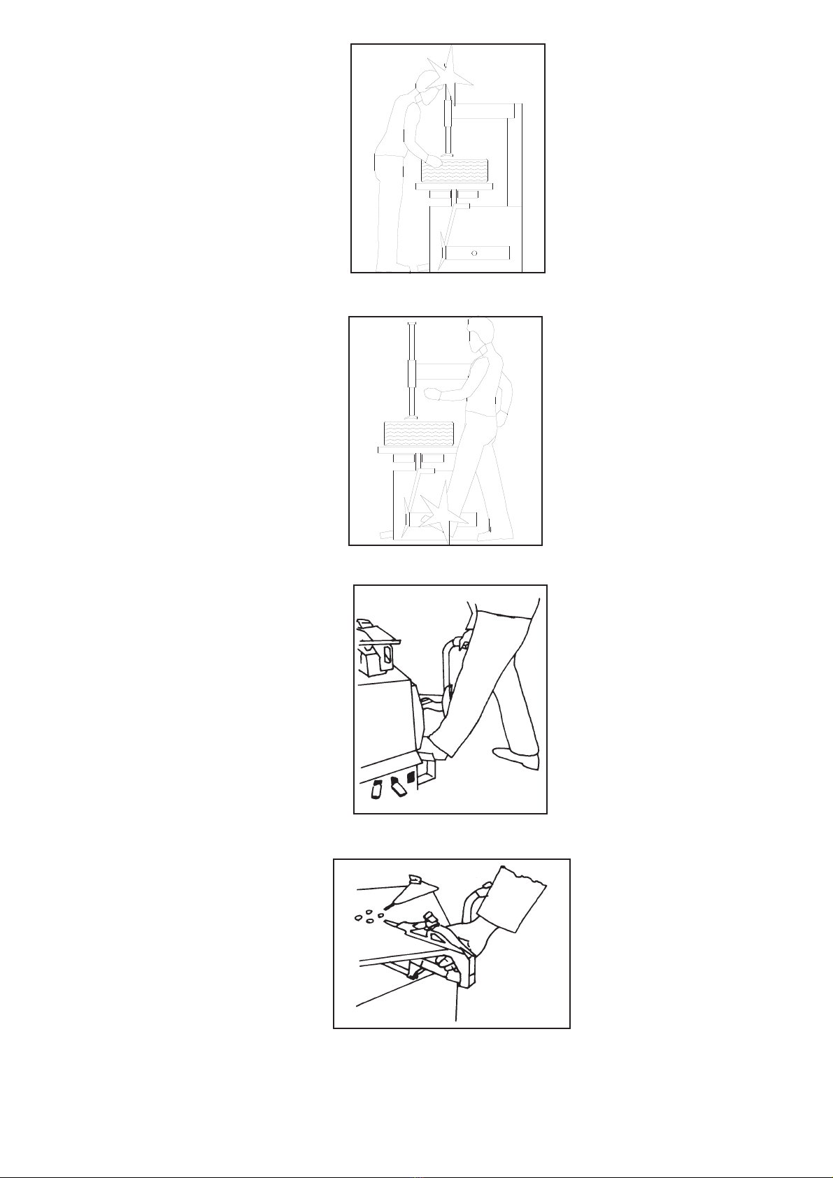
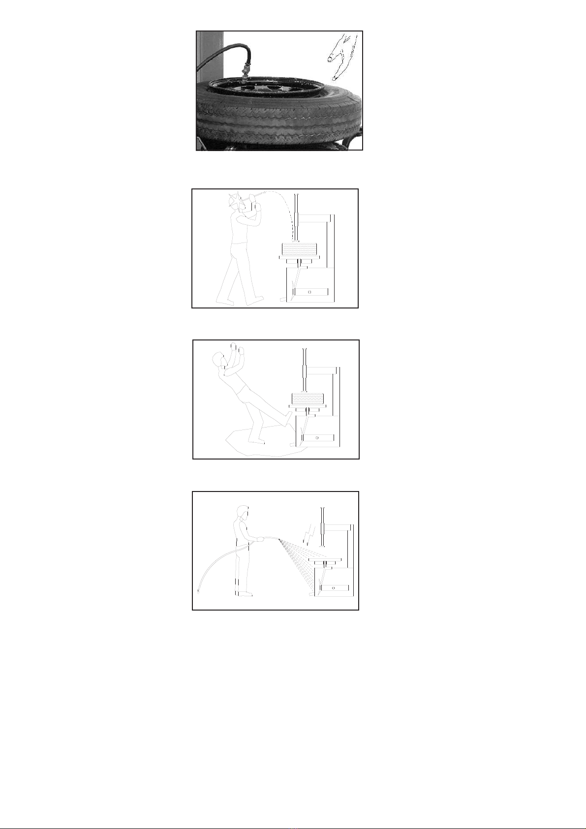
É vietato a chiunque sostare entro la zona di lavo-
ro indicata in fig.11 durante le fasi di lavoro dello
smontagomme.
NON UTILIZZARE LA MACCHINA SENZA LE PRO-
TEZIONI O CON LE PROTEZIONI DISATTIVATE.
IL MANCATO RISPETTO DI QUESTE NORME
PUO’ RECARE GRAVI DANNI ALLE PERSONE E
ALLO SMONTAGOMME.
PRECAUZIONI GENERALI
L’operatore ed il manutentore sono tenuti al rispetto delle prescri-
zioni contenute in leggi e norme antinfortunistiche vigenti nel pae-
se in cui è installato lo smontagomme.
Devono inoltre:
operare sempre dalle postazioni di lavoro previste ed indicate nel
manuale;
non rimuovere nè disattivare i carter e le protezioni meccaniche,
elettriche, o di altra natura;
prestare attenzione agli avvisi di sicurezza riportati nelle targhette
applicate sulla macchina e nel manuale.
Nel testo del manuale gli avvisi di sicurezza saranno evidenziati
nelle forme seguenti:
PERICOLO: Indica un pericolo imminente che può causare danno
alle persone (gravi lesioni o anche la morte).
ATTENZIONE: Indica situazioni e/o comportamenti rischiosi che
possono causare danni alle persone (lesioni più o meno gravi e/o
anche la morte).
CAUTELA: Indica situazioni e/o comportamenti rischiosi che pos-
sono causare danni di minore gravità alle persone e/o danni al
smontagomme, al veicolo o ad altre cose.
RISCHIO DI FOLGORAZIONE: è un particolare avviso di sicurez-
za che viene riportato sul smontagomme, tramite targhetta, in alcu-
ni punti dove è particolarmente elevato il rischio di forti scosse elet-
triche.
CHAPTER 3 SAFETY
It is vital to read this chapter of the manual carefully and from
beginning to end as it contains important information regar-
ding the risks that the operator or maintenance fitter may be
exposed to in case of improper use of the tyre changer.
The following text contains clear explanations regarding some
situations of risk or danger that may arise during the opera-
tion or maintenance of the tyre changer, the safety devices in-
stalled and the correct use of such systems, residual risks
and operative procedures to use (general and specific precau-
tions to eliminate potential hazards).
IWARNING:
Tyre changer is designed and built as a tool to
change tyres on car, motorcycles, or vans wheel
rims. All other uses are unauthorised.
The manufacturer disclaims all liability for injury
to persons or damage to vehicles and other pro-
perty caused by the incorrect and unauthorised
use of the tyre changer.
The operator must remain in the command place
in the respect of all the rules listed below.
The presence of persons inside the danger zone
marked in fig.11 is strictly prohibited during the
tyre changer working operations.
DO NOT USE THE TYRE CHANGER WITHOUT
PROTECTION DEVICES OR WITH THE PROTEC-
TION DEVICES INHIBITED.
FAILURE TO COMPLY WITH THESE REGULA-
TIONS CAN CAUSE SERIOUS INJURY TO PER-
SONS, AND IRREPARABLE DAMAGE TO THE
TYRE CHANGER AND THE VEHICLE BEING LIF-
TED.
GENERAL PRECAUTIONS
The operator and the maintenance fitter are required to observe
the prescriptions of accident prevention legislation in force in the
country of installation of the tyre changer.
Furthermore, the operator and maintenance fitter must:
Always work in the scheduled working area as shown in the ma-
nual.
never remove or deactivate the guards and mechanical, electrical,
or other types of safety devices;
read the safety notices affixed to the machine and the safety infor-
mation in this manual.
In the manual all safety notices are shown as follows:
DANGER: Indicates imminent danger that can result in serious in-
jury or death.
WARNING: Indicates situations and/or types of manoeuvres that
are unsafe and can cause injuries of various degrees or death.
CAUTION: Indicates situations and/or types of manoeuvres that
are unsafe and can cause minor injury to persons and/or damage
the tyre changer, the vehicle or other property.
RISK OF ELECTRIC SHOCK: specific safety notice affixed to the
tyre changer in areas where the risk of electric shock is particularly
high.
6

RISCHI E PROTEZIONI
Vediamo ora quali rischi possono correre gli ope-
ratori o il manutentore nelle fasi d’uso dello smon-
tagomme e quali protezioni sono state adottate dal
costruttore per ridurre al minimo tali rischi:
RISCHIO DI URTO (1)
Con la testa contro al braccio operante. Lavorare
sempre in posizione eretta e facendo attenzione
alle parti sporgenti.
Fig.2 Rischio di urto (1)
RISCHIO DI URTO (2)
Contro alla sporgenza del pistone dello stallonato-
re. Il costruttore ha previsto per il caso, una co-
pertura adeguata. Prestare attenzione comunque
quando si lavora attorno alla macchina.
Fig.3 Rischio di urto (2)
RISCHIO DI SCHIACCIAMENTO DELLA GAMBA
Durante la fase di stallonatura del pneumatico la-
vorare ESCLUSIVAMENTE dalla postazione indi-
cata in fig.4 e soprattutto non infilare la gamba fra
la pala dello stallonatore ed il suo appoggio.
UN USO IMPROPRIO DELLO STAL-
LONATORE PUÒ CAUSARE INCIDEN-
TI GRAVISSIMI.
Fig.4 Rischio di schiacciamento della gamba
RISCHIO DI SCHIACCIAMENTO (2)
Fra i morsetti della tavola autocentrante. Non
infilare mai le mani fra i morsetti della tavola
autocentrante e non azionare mai tali morsetti
senza pneumatico sulla tavola. Durante le fasi
di manutenzione ed ingrassaggio è obbligato-
rio scollegare la macchina da ogni fonte di ali-
mentazione (elettrica e pneumatica).
Fig.5 Rischio di schiacciamento (2)
RISKS AND PROTECTION DEVICES
We shall now examine the risks to which opera-
tors or maintenance fitters may be exposed, toget-
her with the protection devices adopted by the ma-
nufacturer to reduce all such hazards to the mini-
mum:
RISK OF IMPACT (1)
Operator’s head may bump against the operating
arm. Always work keeping an erect position and
paying attention to juts.
Fig.2 Risk of impact (1)
RISK OF IMPACT(2)
Against the juts of the bead-breaker piston. A co-
ver has been projected by the manufacturer, in any
case, the operator has to keep attention while wor-
king.
Fig.3 Risk of impact (2)
RISK OF LEG CRUSHING
During the bead-breaker working phase, the ope-
rator MUST ONLY work from the place marked in
fig.4, above all he must never put his leg between
the bead-breaker and its support.
AN IMPROPER USE OF THE BEAD-
BREAKER MAY CAUSE DEADLY AC-
CIDENTS.
Fig.4 Risk of leg crushing.
RISK OF CRUSHING (1)
Between the self-centring table clamps. Ne-
ver put hands between the clamps and never
set them working without a tyre on the table.
During maintenance and greasing phases
the operator MUST disconnect the machine
from any feeding source (electric or pneuma-
tic).
Fig.5 Risk of crushing (1).
7

RISCHIO DI SCHIACCIAMENTO (2)
Durante l’operazione di gonfiaggio allontana-
re le mani dal tallone del pneumatico.
Fig.6 Rischio di schiacciamento (2)
RISCHIO DI URTO (3)
Prestare molta attenzione nell’uso della leva
alzatallone, in particolare per evitare lo sci-
volamento della stessa nel momento di sfor-
zo e l’eventuale urto contro al viso o altra
parte del corpo.
Fig.7 Rischio di urto (3)
RISCHIO DI SCIVOLAMENTO
Dovuto a zone del pavimento sporche di lu-
brificanti (fig.8).
TENERE PULITA LA ZONA VICINA ALLO
SMONTAGOMME pulendo le MACCHIE
D’OLIO.
Al fine di evitare il rischio di scivolamento
utilizzare i mezzi individuali previsti (scarpe
antinfortunistiche).
Fig.8 Rischio di scivolamento
RISCHIO DI FOLGORAZIONE
Accanto a parti dello smontagomme in cui si
trovano fili elettrici evitate getti d’acqua, di
vapore (da pulitrice a vapore), di solventi o
vernici.
Fig.9 Rischio di folgorazione
RISCHIO DA ILLUMINAZIONE NON IDONEA
L’operatore ed il manutentore devono verificare che tutte le zone
dello smontagomme siano sempre illuminate in maniera uniforme
ed in conformità a quanto previsto dalla normativa vigente nel
luogo di installazione.
RISCHIO DI ANOMALIE DURANTE IL FUNZIONAMENTO
Nel caso in cui l’operatore avvertisse rumori e vibrazioni anomale o
comunque tali da comportare una situazione di pericolo deve im-
mediatamente arrestrare la fase di lavoro, sconnettere lo smonta-
gomme dalla rete elettrica ed avvertire il centro di assistenza auto-
rizzato indicato nel frontespizio
RISK OF CRUSHING (2)
keep hand away from the tyre during blowing
up operation.
Fig.6 Risk of crushing (2).
RISK OF IMPACT(3)
Pay attention to the bead-lifting lever, in particu-
lar to avoid its slipping in the stress moment,
and to avoid its bumping against the operator.
Fig.7 Risk of impact (3).
SLIPPING
This risk may arise due to spillage of lubricants
in the surrounding area (fig.8).
ALWAYS KEEP THE AREA SURROUNDING
THE TYRE CHANGER CLEAN by removing
all OIL SPILLS.
To avoid the risk of slipping, make use of the
recommended personal protection (anti-slip
footwear).
Fig.8 Slipping risk
RISK OF ELECTRIC SHOCK
Risk of electric shock in areas of the tyre chan-
ger housing electrical wiring.
Do not use jets of water, steam (high pressure
wash units), solvents or paint near the tyre
changer.
Fig.9 Risk of electric shock
RISKS RELATED TO INAPPROPRIATE LIGHTING.
The operator and the maintenance fitter must be able to assure
that all the areas of the tyre changer are properly and uniformly illu-
minated in compliance with the laws in force in the place of instal-
lation.
RISK OF ANOMALY DURING OPERATION
If the operator hears unusual noises or vibrations or something that
may be dangerous, he must immediately stop the working phase,
unplug the tyre changer and call the authorised service centre mar-
ked on the frontispiece.
8

RISCHIO DI ROTTURE DI COMPONENTI DURANTE IL
FUNZIONAMENTO
Il costruttore ha utilizzato materiali e procedure progettuali e co-
struttive idonee all’uso previsto e atte a creare un’apparecchiatura
affidabile e sicura ma è necessario rispettare l’uso per cui è stato
progettato lo smontagomme nonchè le frequenze delle ispezioni e
delle manutenzioni consigliate nel capitolo 6 “MANUTENZIONE”.
RISCHI A TERZI
L’operatore deve accertarsi che non vi siano persone vicino allo
smontagomme durante le normali o straordinarie fasi di lavoro e di
manutenzione.
Ogni uso dello smontagomme, diverso da quello per cui è sta-
to progettato può creare incidenti, anche molto gravi, alle per-
sone che stanno lavorando nelle immediate vicinanze.
É pertanto estremamente importante attenersi scrupolosa-
mente a tutte le regole riguardanti l’uso, la manutenzione e la
sicurezza riportate in questo manuale.
AVVISI DI SICUREZZA E TARGHETTE APPLICATI SULLA
MACCHINA.
Fig.10 Avvisi di sicurezza e targhette applicati alla macchina
RISK OF COMPONENT FAILURE DURING OPERATION.
The manufacturer has used appropriate materials and construction
techniques in relation to the specified use of the machine in order
to manufacture a reliable and safe tyre changer. Note however,
that the tyre changer must be used in conformity with manufactu-
rer’s prescriptions and the frequency of inspections and mainte-
nance work recommended in chapter 6 “MAINTENANCE” must be
observed.
RISKS TO OTHER PEOPLE
The operator must check unauthorised persons are not near the
tyre changer during operation and maintenance phases.
All uses of the tyre changer other than the uses for which it
was designed are liable to give rise to serious accidents invol-
ving the persons working in the immediate vicinity of the unit.
It is therefore essential to adhere scrupulously to all regula-
tions regarding use, maintenance and safety contained in this
manual.
SAFETY NOTICES AND DATA PLATES AFFIXED TO THE
MACHINE
Fig.10 Safety notices and data plates affixed to the machine
9

CAP.4 INSTALLAZIONE
QUESTE OPERAZIONI SONO DI COMPETENZA ESCLUSIVA
DEI TECNICI SPECIALIZZATI INCARICATI DAL COSTRUTTO
-
RE O DAI RIVENDITORI AUTORIZZATI .
SE EFFETTUATE DA ALTRE PERSONE POSSONO CREARE
SITUAZIONI DI PERICOLO E CAUSARE GRAVI DANNI ALLE
PERSONE E/O ALLO SMONTAGOMME.
VERIFICA DEI REQUISITI PER L’INSTALLAZIONE
Lo smontagomme è costruito per l’impiego in locali chiusi e ripara-
ti. Il luogo prescelto non deve essere vicino a lavaggi, a posti di
verniciatura, a depositi di solventi o vernici, a locali con lavorazioni
che possono creare atmosfere esplosive.
VERIFICA DI IDONEITÀ DELLE DIMENSIONI DEL LOCALE E
DELLE DISTANZE DI SICUREZZA.
Lo smontagomme deve essere installato rispettando le distanze di
sicurezza da muri,colonne, altre macchine, ecc... come indicate in
fig.11 e secondo le eventuali prescrizioni della legislazione vigente
nel luogo di installazione.
Verificare in particolare che la distanza dai muri permetta un facile
accesso a tutte le parti della macchina, una buona movimentazio-
ne dei pneumatici, una zona di lavoro ottimale ed ampia per l’ope-
ratore, nonchè almeno 500 mm per un’eventuale via di fuga in
caso di emergenza.
Verificare inoltre la possibilità di effettuare l’allacciamento all’im-
pianto elettrico e pneumatico.
Fig.11 Distanze di sicurezza
ILLUMINAZIONE
Tutte le zone della macchina devono essere illuminate in modo
uniforme e sufficiente per garantire le operazioni di regolazione e
manutenzione previste nel manuale, evitando zone d’ombra, rifles-
si, abbagliamento e affaticamento della vista.
L’illuminazione deve essere realizzata in accordo con la normativa
vigente nel luogo di installazione (a cura dell’installatore dell’im-
pianto di illuminazione).
PAVIMENTO
Lo smontagomme deve essere installato su platea orizzontale.
Il pavimento deve inoltre essere piano e ben livellato (10 mm di tol-
leranza sul livellamento) e deve sopportare ampiamente il peso
della macchina.
Nel caso di applicazioni particolari, interpellare il costruttore.
CHAPTER 4 INSTALLATION
THE FOLLOWING OPERATIONS MUST BE PERFORMED EX-
CLUSIVELY BY SPECIALISED TECHNICAL STAFF WITH AUT-
HORISATION FROM THE MANUFACTURER OR LICENSED
DEALER.
IF THESE OPERATIONS ARE PERFORMED BY OTHER PER-
SONS, SERIOUS PERSONAL INJURY AND/OR IRREPARABLE
DAMAGE TO THE TYRE CHANGER UNIT MAY RESULT.
INSTALLATION REQUISITE CHECKLIST
The tyre changer is designed for installation in enclosed areas sui-
tably protected from the weather. The place of installation must be
well clear of areas destined to washing or painting, and away from
solvent or paint storage areas or areas where there is a risk of po-
tentially explosive atmosphere.
SUITABILITY OF THE DIMENSIONS OF THE PLACE OF
INSTALLATION AND SAFETY CLEARANCES.
The tyre changer must be installed in observance of the clearan-
ces between walls, pillars, other machines, etc. indicated in Figure
11 and in compliance with any legislative requirements in the coun-
try of installation.
Check in particular that the distance from walls is enough to permit
an easy access to every part of the machine, a good moving of ty-
res, a good and wide working area for the operator, and at least,
500mm for a possible way of escape in case of danger.
Also check proximity to power supply and pneumatic connection
for trouble-free hook-up.
Fig.11 Safety distances
LIGHTNING
All parts of the machine must be uniformly lit with sufficient light to
assure that the adjustment and maintenance operations specified
in the manual can be performed, and without areas of shadow, re-
flected light, glare and avoiding all situations that could give rise to
eye fatigue.
The lighting must be installed in accordance with the laws in force
in the place of installation (responsibility lies with the lighting
equipment fitter).
FLOOR
The tyre changer must be installed on a horizontal concrete bed.
The floor must also be flat and level (10 mm of tolerance for level-
ling).
Consult the manufacturer with regard to special applications.
10

MONTAGGIO
IATTENZIONE
DURANTE IL MONTAGGIO NON É AMMESSO NESSUN
ESTRANEO AI LAVORI
MONTAGGIO DELLA COLONNA
1) Appoggiare la colonna sul cassone (fig.12).
Fig.12
2) Inserire la spina (1) bloccarla con la piastrina e la vite
TCEI M5x10 posto sulla torretta (fig.12)
3) Ancorare il cilindro (2) alla colonna per mezzo della vite (3)
4) Regolare la vite (4) nella posizione della vite (5) (fig.14)
5) Collegare il tubo (6) al raccordo intermedio (7) (fig.15)
Fig.14
ASSEMBLING
IWARNING
DURING INSTALLATION ONLY AUTHORISED PERSONNEL IS
ALLOWED
POST ASSEMBLY
1 - Lean the post on the tyre changer chassis (fig. 12).
Fig.13
2 - Insert the pin (1) blocking it with the plaque and screw
TCEI M5x10 on the tower (fig.12).
3 - Block the cylinder (2) against the post with the screw (3).
4) - Adjust the headless screw (4) in its place (5)(fig.14)
5) - Connect the pipe (6) to the fitting in the middle (7) (fig.15)
Fig.15
11
1
3
2
4
5
7
6

MONTAGGIO DELL’ALBERO PORTAUTENSILE
1) Svolgere il pacco contenente l’albero portautensi-
le.
2) Con una pinza per seeger togliere il seeger (1)
quindi sfilare il tappo spingimolla (2) e la relativa mol-
la (3).
3) Controllare che sulla parte inferiore dell’albero (4)
sia presente l’ammortizzatore (5).
Fig.16
4) Inserire l’albero (5) nella sede esagonale del braccio operante
facendo attenzione alla posizione corretta dell’utensile come indi-
cato in figura 17.
Fig.17
5) L’albero portautensili fuoriesce dal foro del carter superiore: in-
serire la molla (3, fig.16) nell’albero, il tappo spingimolla sulla mol-
la, quindi tenendolo premuto, fissare con il seeger (1, fig.16) come
da fig.18.
Fig.19
6) Montare il carter anteriore colonna (fig.19) ed il carter copertura
torrette (fig.20)
ASSEMBLING THE TOOL-CARRYING SHAFT
1 - Open the package containing the tool-carrying
shaft.
2 - Take the seeger(1) off with seeger-pincers, then
the spring thrusting cap (2) and the spring (3).
3 - Check the shock absorber (5) is in the lower part of
the tool-carrying shaft(4).
4 - Insert the tool-carrying shaft in its hexagonal place on the ope-
rating arm, minding its correct position as showed in fig. 17.
Fig.18
5 - The tool-carrying shaft comes out from the drill on the upper
guard: insert the spring (3, fig.16) in the tool-carrying shaft, the
spring-thrusting cap on the spring, then, pressing, fix everything
with the seeger (1, fig.16) as shown in fig. 18.
Fig.20
6) Assembly arm upper guard (fig.19) and turret guard (fig.20).
12
4
2
3
1
5

MONTAGGIO DEL BRACCIO STALLONATORE
1) Il braccio stallonatore viene fornito già inserito nelle orecchie po-
ste sul cassone.
2) Infilare il perno nel foro, quindi bloccare il perno con i relativi
seeger (fig.21).
Fig.21 Montaggio del perno sul braccio stallonatore
Fig.21 Assembling the pin on the bead-breaker arm.
3) Inserire la pala dello stallonatore nella relativa sede del braccio
stallonatore (fig.22) quindi inserire la vite di bloccaggio ed avvitare
il dado autobloccante, serrando in modo da lasciare il gioco neces-
sario al movimento della pala ma sufficientemente chiuso da impe-
dirne la caduta spontanea.
4) Inserire lo stelo dello stallonatore nel foro del perno già inserito
nel braccio stallonatore (fig.23).
ATTENZIONE: la parte piana del perno dovrà essere tenuta verso
l’esterno come indicato in fig.24.
Fig.23
5) Avvitare il dado sullo stelo del
perno dello stallonatore facendo at-
tenzione che il dado appoggi sulla
parte piana del perno (fig.24).
6) Agganciare la molla del braccio
stallonatore nell apposito foro predi-
sposto sul cassone (fig.25)
Fig.25 Aggancio della molla
BEAD-BREAKER ARM ASSEMBLING
1 - The bead-breaker arm is given already inserted in the ears on
the chassis.
2 - Insert the pin into the drill, then block it with its seegers (fig.21)
Fig.22 Fissaggio della pala
Fig.22 Scoop fixing
3 - Insert the bead-breaker scoop in its place on the extruding arm
(Fig.22), insert the blocking screw into the self-blocking nut, tighten
it in order to prevent its falling, but leave the necessary play for the
scoop to move.
4) - Insert the bead-breaker rod into the drill of the already inserted
pin (Fig. 23).
ATTENTION: the pin flat side is to be kept towards the outside as
shown in fig. 24.
Fig.24
5 - Tighten the nut on the pin rod;
the nut must lay on the pin flat
side (fig.24
6) Insert the extruding arm pin
into its drill made on the chassis.
(fig.25).
Fig.25 Spring fixing
13

MONTAGGIO DEL TAMPONE STALLONATORE
1) Montare il tampone in plastica (19) posizionandolo sul cassone
in corrispondenza del punto Q facendo attenzione che il dente po-
sto sul tampone stesso sia rivolto verso la pedaliera quindi preme-
re con forza per ottenere l’incastro del tampone sul supporto
(fig.26).
Fig.26 Montaggio del tampone
BLOCCAGGIO DELLA MACCHINA AL SUOLO
É necessario, per un sicuro funzionamento della macchina, che
questa venga fissata al suolo mediante tasselli ad espansione.
1) Usando i fori nelle asole di fissaggio del cassone come dima di
foratura, forare il pavimento con una punta elicoidale adeguata del
diametro di 15 mm. ed una profondità di 70 mm. (fig.27).
Fig.27 Foratura del pavimento
Fig.27 Floor drilling.
2) Spostare lo smontagomme ed inserire i tasselli nei fori quindi ri-
posizionare la macchina dove andrà fissata.
3) Inserire le viti nei tasselli e serrare con una chiave dinamometri-
ca tarata a 25 N/m.
BUFFER BEAD-BREAKER FIXING
1 - Fix the plastic buffer (19) on the chassis in correspondence of
point “Q” paying attention that the tooth on the buffer is directed to-
wards the pedals, push with strength to make the buffer fit in its
support. (fig.26)
Fig.26 Plastic buffer fixing.
MACHINE FIXING ONTO FLOOR
For a good functioning, the machine must be fixed onto the floor
with expansion dowels.
1 - Drill the floor with a helical concrete bit with a diameter of
15mm. to a depth of 70mm., using the holes in the base as a dril-
ling template (fig. 27).
Fig.28 Fissaggio al suolo della macchina
Fig.28 Machine fixing onto floor.
2 - Move the tyre changer and insert anchor bolts into the drills,
then set the machine in the place to be fixed.
3 - Insert into the anchor bolts and use a torque wrench (setting of
25 N/m) to tighten.
14
16
Q

ALLACCIAMENTO IMPIANTO ELETTRICO
IATTENZIONE
Le operazioni sottoelencate devono essere eseguite da perso-
nale qualificato.
1) Prima del collegamento elettrico verificare che :
·l’impianto di alimentazione al smontagomme sia dotato delle
protezioni previste dalle norme vigenti nel paese in cui viene in-
stallato.
·la linea di alimentazione abbia le seguenti caratteristiche :
Tensione smontagomme 400V trifase:minimo 2,5 mm2
·le oscillazioni di tensione rientrino nel campo di tolleranza previ-
sto dalle specifiche.
Eseguire l’allacciamento ad una presa protetta da fusibili e
salvavita differenziale.
ALLACCIAMENTO ALL’IMPIANTO PNEUMATICO
Collegare una sorgente di aria compres-
sa che eroghi una pressione compresa
fra i 9 e i 12 bar, alla presa relativa nel re-
tro dello smontagomme come indicato in
fig.29
Fig.29 Punto di aggancio dell’aria compressa
COLLAUDI E CONTROLLI DA EFFETTUARE PRIMA
DELL’AVVIAMENTO
VERIFICHE MECCANICHE
·Fissaggio e serraggio bulloni, raccordi e connessioni;
·Scorrimento libero delle parti mobili;
·Pulizia delle varie parti della macchina;
·Posizione delle protezioni.
VERIFICHE ELETTRICHE
·Collegamenti corretti secondo gli schemi;
·Messa a terra della macchina;
VERIFICA DEL SENSO DI ROTAZIONE
·della tavola autocentrante: premendo il pedale 5, fig.30, il senso
di rotazione deve essere orario; in caso contrario invertire due
fasi nella connessione elettrica.
VERIFICA DEL SISTEMA DI LUBRIFICAZIONE
·Verificare che dalla spia (fig.29) del lubrificatore cada una goccia
d’olio ogni cinque movimenti circa.
ELECTRIC PLANT CONNECTION
IATTENTION
The operations listed below must be performed by skilled per-
sonnel.
1) Before connecting the electric plant, make sure that:
·the power supply plant to the tyre changer is equipped with the
protection devices by current standards in the country where the
machinery is installed.
·the power supply line has the following characteristics:
tyre changer voltage:400V 3-ph. min. 2,5 mm2
·voltage oscillations are within the tolerance range set forth by
the specification
Connect the tyre changer to a socket with fuses and voltage
difference save-life switch
PNEUMATIC PLANT CONNECTION
Connect a compressed air source with a
pression between 9 and 12 bar to the relati-
ve intake in the back side of the tyre chan-
ger, as shown in fig. 29.
Fig.29: Connecting point for compressed air.
TESTING AND CHECKS TO PERFORM BEFORE START-UP
MECHANICAL TESTS
·Attachment and tightness of bolts, fittings and connections;
·Free sliding of moving parts;
·Clean state of various parts of the machine;
·Position of the protection devices.
ELECTRICAL TESTS
·Connections comply with diagrams;
·Machine earth connection;
DIRECTION OF ROTATION TEST
·of the self-centring table: pushing pedal 5 (fig.30) the table must
rotate in a clockwise direction; on the contrary, switch two power
supply phases.
HYDRAULIC OIL TEST
·Check that from the lubricator spy one oil drop drops every 5
movements.
15

CAP.5 FUNZIONAMENTO ED USO
I comandi dello smontagomme sono i seguenti:
Pedale 1: Premendolo si aziona la pistola di gonfiaggio del pneu-
matico.
Nel caso sia presente l’INFLATOR®, premendo il pedale fino a
metà corsa si aziona la pistola di gonfiaggio, premendo a fondo si
ottiene l’azione combinata della pistola e dell’INFLATOR®
Pedale 2: Azionatore colonna.
Sollevando il pedale la colonna si ribalta.
(La velocità di ribaltamento della colonna varia utilizzando i regola-
tori montati sulla valvola di comando).
Pedale 3: Premendo questo pedale si ottiene l’apertura dei morset-
ti della tavola autocentrante che bloccano il cerchio.
Pedale 3: Questo pedale chiude i morsetti della tavola autocen-
trante quindi libera il cerchio.
Pedale 4: Premendo questo pedale la pressione manda in avvio il
cilindro dello stallonatore con la conseguente stallonatura del
pneumatico. Rilasciando il pedale si ottiene il ritorno dello stelo ed
il conseguente rilascio del pneumatico stallonato.
Pedale 5:Premendolo si ottiene la rotazione oraria della tavola au-
tocentrante (fig.30); Sollevandolo si ottiene la rotazione antioraria
della tavola autocentrante.
Fig.30 Comandi pedaliera
CHAPTER 5 OPERATIONS AND USE
The tyre changer, has the following commands:
Pedal12: this pedal makes the clamps on the self-centring table
open, to tight on to the rim.
Pedal 1: Push this pedal to activate the tyre inflating gun.
With INFLATOR®, if the pedal is pushed up to half stroke the tyre
inflating gun is activated. If the pedal is pushed to the end of its
stroke, the joint action of INFLATOR® and tyre inflating gun is ob-
tained.
Pedal 2: post
when the pedal is lifted, the post will turn over. (Post turning over
speed can be varied using the regulators on the command valve).
Pedal 3: this pedal makes the clamps on the self-centring table
open, to tight on to the rim.
Pedal 3: this pedal makes the clamps on the self-centring table
close, to loosen the rim.
Pedal 4: This pedal makes the pressure and the bead breaker
cylinder begins to work; consequently, the tyre bead is de tachen.
When releasing it, the bead breaker rod comes back and the tyre
released.
Pedal 5: it makes the self-centring table rotate clockwise (fig.30),
when pushed. When lifted, it makes the self-centring table rotate
anticlockwise.
Fig.30 Pedals.
16
23
145

USO
L’uso dello smontagomme è consentito solamente al persona-
le d’officina che sia preparato a tale uso e che conosca bene il
presente manuale in ogni sua parte.
UN USO IMPROPRIO O NON CONSENTITO PUÒ
CAUSARE GRAVI DANNI ALLE PERSONE ED
AGLI OGGETTI.
STALLONATURA
1) Sgonfiare completamente il pneumatico.
2) Posizionare il pneumatico contro il tampone dello stallonatore
quindi accostare la pala al bordo del cerchio e premere il pedale
dello stallonatore (fig.30) fino ad ottenere lo scollamento del tallone
dal cerchio (fig.31).
Fig.31 Stallonatura del pneumatico
IATTENZIONE
l’unica postazione e posizione di lavoro consenti-
ta è quella indicata in figura 31.
OGNI ALTRA POSIZIONE NON È CONSENTITA E PUÒ CAUSA
-
RE LO SCHIACCIAMENTO DELLA GAMBA FRA LO STALLO
-
NATORE E IL TAMPONE CAUSANDO DANNI DI GRAVISSIMA
ENTITÀ ALL’OPERATORE
Per facilitare la stallonatura di pneumatici particolarmente duri si
consiglia di esercitare brevi pressioni su diversi punti del cerchio-
ne, per evitare danneggiamenti al tallone.
Verificare che lo scollamento del pneumatico avvenga su tutta la
circonferenza del cerchione.
Dopo la stallonatura lubrificare i talloni del pneumatico con apposi-
to grasso (tipo XXXX)
USE
Authorised personnel only can use the tyre changer; person-
nel must be instructed and know this handbook perfectly.
AN IMPROPER OR UNAUTHORISED USE MAY
DAMAGE PEOPLE AND THINGS.
BEAD BREAKING
1 - Flatten the tyre completely.
2 - Put the tyre against the bead breaker buffer, approach the
scoop to the tyre edge, push the pedal on the bead breaker handle
(fig.30) until the bead detaches itself from the rim. (fig.31)
Fig. 31 Tyre bead breaking.
IATTENTION
The only permitted operator’s position is the one
shown in fig.31.
ANY OTHER POSITION IS NOT ALLOWED, AS IT MAY CAUSE
THE CRUSHING OF THE OPERATOR’S LEG BETWEEN THE
BEAD BREAKER AND THE BUFFER, AND VERY SERIOUS DA-
MAGES TO THE OPERATOR HIMSELF.
To operate easily with particularly hard tyres, make short pressions
on different bead points, in order to avoid damaging the bead.
Check the tyre detaches from all the rim surface.
After the bead breaking, lubricate the rim beads with the special
grease (type xyxyxy)
17

BLOCCAGGIO CERCHIO
3) Posizionare la ruota sulla tavola autocentrante verificando che i
morsetti della tavola siano chiusi se si vuole agganciare la ruota
all’interno oppure aperti se la ruota deve essere agganciata all’e-
sterno.
Fig.33 Aggancio del cerchione dall’interno
Fig.33 Rim blocked from the inside.
SMONTAGGIO PNEUMATICO
1) Prendere il pneumatico con entrambe le mani e muoverlo alcu-
ne volte verso l’alto per essere certi dello scollamento del tallone.
2) Accostare premendo l’utensile al bordo del cerchione; abbassa-
re il perno dell’utensile fino a che l’utensile si posiziona sulla cir-
conferenza esterna del cerchione (fig.35) quindi, bloccarlo con
l’apposito comando (1 fig.36).
Fig.35
3) Con l’aiuto della leva alzatallone, che andrà posizionata nell’ap-
posita sede dell’utensile (fig.37-38), portare il tallone del pneumati-
co sull’utensile tenendo premuto, con una mano, la parte opposta
del pneumatico.
Fig. 37
RIM BLOCKING
3 - Set the wheel on the self-centring table. The clamps are to be
closed if one wants the wheel to be blocked from the inside, ope-
ned, if one wants the wheel to be blocked from the outside.
Fig.34 Aggancio del cerchione dall’esterno
Fig 34 Rim blocked from the outside.
TYRE DISASSEMBLING
1 - Take the tyre with both hands and move it some times upwards
to make sure of the bead detachment.
2 - While pushing, approach the tool to the rim edge; lower the tool
pin until the tool is on the outside rim circumference (fig.35), then
block the tool with its command (1, fig.36).
Fig.36
3 - Helped by
the bead-lifting lever (set in its fitting place on the tool) (fig.37-38)
make the tyre bead go onto the tool, keeping the tyre opposite side
pushed with a hand.
Fig.38
18
1
Table of contents
Other WERTHER INTERNATIONAL Tyre Changer manuals
Popular Tyre Changer manuals by other brands

ATLAS PLATINUM
ATLAS PLATINUM PTC 500 Use and maintenance instruction manual

Coats
Coats Rim Clamp 9024 installation instructions

Fasep
Fasep RGU588E Installation, use and maintenance guide

Corghi
Corghi ARTIGLIO 50 Operator's manual

Hunter
Hunter TCX56 operating instructions

GIULIANO
GIULIANO S224 Installation, operation and maintenance guide

Fasep
Fasep RGU600E instruction manual

Aston Global
Aston Global ATC-T5 Installation, operation and maintenance

Atlas
Atlas TC289 Installation & operation manual

Corghi
Corghi A 2030 Operator's manual

Dannmar
Dannmar T-100 Installation and operation manual

Ranger
Ranger R30XLT Installation and operation manual