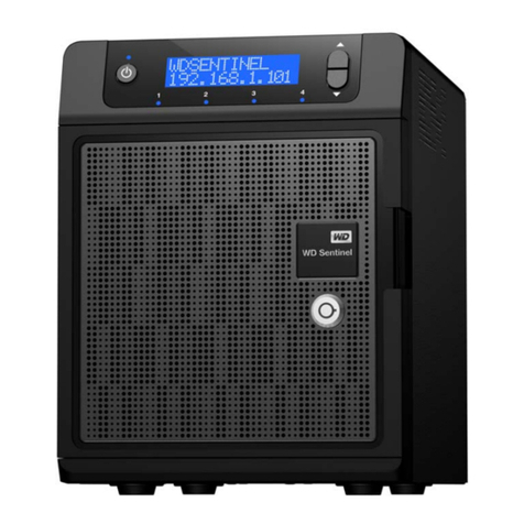
Western Digital HGST Ultrastar Serv24-HA User manual

Contents
Revision History..............................................................................................4
Points of Contact.............................................................................................5
Copyright........................................................................................................6
Chapter 1 Ultrastar Serv24-HA Overview.................................................7
1.1 Ultrastar®Serv24-HA Description......................................................7
1.2 Ultrastar Serv24-HA Specification Summary.....................................8
1.3 System Architecture Overview...........................................................9
1.4 Ultrastar Serv24-HA Layout...............................................................9
1.5 Ultrastar Serv24-HA Rack Requirements........................................10
1.6 List of Replaceable Components.....................................................10
1.7 Supported SKUs..............................................................................11
1.8 List of Compatible Drives.................................................................11
Chapter 2 Safety.......................................................................................12
2.1 Electrostatic Discharge....................................................................12
2.2 Optimizing Location..........................................................................12
2.3 Power Connections..........................................................................12
2.4 Power Cords.....................................................................................13
2.5 Replaceable Batteries......................................................................13
2.6 Rackmountable Systems.................................................................13
2.7 Safety and Service...........................................................................14
2.8 Safety Warnings and Cautions.........................................................14
Chapter 3 Packaging................................................................................15
3.1 Ultrastar Serv24-HA Packaging Overview.......................................15
3.2 Ultrastar Serv24-HA Unpacking Procedure.....................................15
ii
Contents
Installation Guide

Chapter 4 Installation...............................................................................16
4.1 Ultrastar Serv24-HA Installation Overview.......................................16
4.2 Battery Backup Installation..............................................................16
4.3 Ultrastar Serv24-HA Installation Procedure.....................................20
Chapter 5 Initial Bringup..........................................................................26
5.1 Bringing Up the Enclosure...............................................................26
Appendix A System Operations Appendices..............................................30
A.1 ESD.................................................................................................30
A.2 System Cooling................................................................................30
A.3 Power Requirements.......................................................................30
A.4 Host Connectivity.............................................................................31
iii
Contents
Installation Guide

Revision History
CommentRevisionDate
Initial ReleaseRevision 1.0February 2018
• Updated the Ultrastar
Serv24-HA Installation Procedure on page 20
Revision 1.1April 2018
• Added the Battery Backup Installation on page 16 section to the
Installation on page 16
Added the Battery Backup latch. See: Battery Backup Installation
on page 16.
Revision 1.2May 2018
Updated the following: • List of Replaceable Components on page
10
Revision 1.3August 2018
4
Revision History
Installation Guide

Points of Contact
For further assistance with an HGST product, contact Global Service and Support. Please be prepared to
provide the following information: Serial Number (S/N), product name, model number, and a brief description
of the issue.
Email:
Website:
http://support.hgst.com
5
Points of Contact
Installation Guide

Copyright
The following paragraph does not apply to the United Kingdom or any country where such provisions
are inconsistent with local law: HGST a Western Digital company PROVIDES THIS PUBLICATION "AS
IS" WITHOUT WARRANTY OF ANY KIND, EITHER EXPRESS OR IMPLIED, INCLUDING, BUT NOT
LIMITED TO, THE IMPLIED WARRANTIES OF MERCHANTABILITY OR FITNESS FOR A PARTICULAR
PURPOSE. Some states do not allow disclaimer or express or implied warranties in certain transactions,
therefore, this statement may not apply to you.
This publication could include technical inaccuracies or typographical errors. Changes are periodically made
to the information herein; these changes will be incorporated in new editions of the publication. HGST may
make improvements or changes in any products or programs described in this publication at any time.
It is possible that this publication may contain reference to, or information about, HGST products (machines
andprograms),programming, or services that are not announced in yourcountry.Suchreferences or information
must not be construed to mean that HGST intends to announce such HGST products, programming, or
services in your country.
Technical information about this product is available by contacting your local HGST representative or on the
Internet at: support.hgst.com
HGST may have patents or pending patent applications covering subject matter in this document. The furnishing
of this document does not give you any license to these patents.
Copyright ©2017-2018 Western Digital Corporation or its affiliates.
Western Digital
5601 Great Oaks Parkway
San Jose, CA 95119
Long Live Data™is a trademark of HGST, Inc. and its affiliates in the United States and/or other countries.
HGST trademarks are authorized for use in countries and jurisdictions in which HGST has the right to use,
market and advertise the brands.
Other product names are trademarks or registered trademarks of their respective owners.
One MB is equal to one million bytes, one GB is equal to one billion bytes, one TB equals 1,000GB (one trillion
bytes) and one PB equals 1,000TB when referring to storage capacity. Usable capacity will vary from the raw
capacity due to object storage methodologies and other factors.
References in this publication to HGST products, programs or services do not imply that HGST intends to
make these available in all countries in which HGST operates.
Product information is provided for information purposes only and does not constitute a warranty.
Information is true as of the date of publication and is subject to change. Actual results may vary. This publication
is for general guidance only. Photographs may show design models.
6
Copyright
Installation Guide

Chapter
1
1 Ultrastar Serv24-HA Overview
1.1 Ultrastar®Serv24-HA Description
Figure 1: Ultrastar Serv24-HA
The Ultrastar®Serv24-HA is a high availability 2U, 24 bay, dual node storage server. The maximum data
storage capacity of the Ultrastar Serv24-HA is 184.32 TB using HGST Ultrastar®SN200 drives. For a full list
of compatible drives and total storage capacities, see the List of Compatible Drives on page 11. The
enclosure runs on an input voltage of 200-240VAC and consumes ~1800W under typical conditions. It is
designed to fit within a 2U rack space and requires a minimum of See EIA-310 Rack Standard.
• 2U Storage Server
• 24 NVMe drives
• Redundant 1800W PSUs
• Two hot-swappable Compute Canisters (each list item represents the content of one Compute Canister)
• Contains a Intel Purely platform motherboard
• Dual Skylake processor design with Lewisburg PCH
• Supports up to 12 DIMMs per CPU, 24 per Compute Canister
• Five fan modules
• Aspeed AST2500 Board Management Controller (BMC)
• Three PCIe generation 3 slots (one slot open for user expansion)
• Two M.2 boot drives
• Two dual-port 100 GbE NIC cards
• One VGA port
• Two USB 3.0 ports
• Four 10 GbE ports (per Compute Canister)
• One 1 GbE port for system management that can be controlled through IPMI or Web UI
• (optional) TPM Module
• (optional) Battery Back-up Module
7
1 Ultrastar Serv24-HA Overview
Installation Guide 1.1 Ultrastar®Serv24-HA Description

1.2 Ultrastar Serv24-HA Specification Summary
Table 1: Environmental Specification Summary
OperationalNon-OperationalSpecification
5°C to 35°C-40°C to 60°CTemperature
20°C per hour max30°C per hour maxTemperature Gradient
1°C per 300m above 950m1°C per 300m above 12000mTemperature De-rating
8-85% Non-Condensing8-95% Non-CondensingRelative Humidity
30% per hour maximum30% per hour maximumRelative Humidity Gradient
950m to 3048m950m to 12000mAltitude
Table 2: Electrical Specifications
ValueSpecification
~1980W (for one second)Max Power Consumption
~1800WTypical Power Consumption
200-240VACInput Voltage
C14PSU Connector Type
AC line inrush current shall not exceed 30A peak,
for up to one-quarter of the AC cycle, after which,
Inrush Current Maximum (per PSU)
the input current should be no more than the
specified maximum input current.
80 Plus™PlatinumPSU Efficiency
Table 3: Mechanical Specifications
OperationalNon-OperationalSpecification
10G - 5 ms duration; 5 shocks
positive and 5 negative in each of
3 axes, 30 total shocks.
35G - 136 in/sec trapezoid waveShock
0.278G - Random 5-500 Hz 30
minutes per axis, 3 axes (X, Y, Z)
1.04G - 2~200Hz, 15
minutes/faces, six product faces
Vibration
43 kg / 94.8 lbsWeight
48.4 kg / 106.8 lbsWeight w/ Rails
W: 446.4 mm x L:825mmxH: 87.6 mm / W: 17.58in. x L: 32.5in. x
H: 3.4in.
Dimension
482.6 mm / 19 in.Required Rack Width
See EIA-310 Rack StandardRequired Rack Depth
8
1 Ultrastar Serv24-HA Overview
Installation Guide 1.2 Ultrastar Serv24-HA Specification Summary

OperationalNon-OperationalSpecification
2URack Units (U)
Table 4: Data Capacity Specifications
ValueSpecification
24Number of Drive Slots
184.32 TBMax Raw Data Storage Capacity
1.3 System Architecture Overview
TheUltrastarServ24-HA consists of a main chassis that is populated with up to24NVMedrives,twoCompute
Canisters, and redundant 1800W PSUs. Each Compute Canister contains physical connections for dual CPUs,
a platform controller hub (PCH), 24 DIMM sockets, three PCIe generation 3 slots (one slot open for user
expansion), a system BMC, and a removable Trusted Platform Module (TPM). The Ultrastar Serv24-HA
contains four Skylake CPUs (two per Compute Canister) that manage and direct the instructions to the
necessary component in the enclosure. The CPUs supports 1.0 MB Mid-Level Cache (MLC) and Intel
Hyper-Threading Technology per core. The Ultrastar Serv24-HA uses a Lewisburg PCH combined with the
Skylake Server to provide more bandwidth and flexibility in the I/O. It allows for better management of power
within the enclosure and the enclosure components.
The out-of-band management is controlled through Integrated Remote Management Processor system BMC.
Each Compute Canister provides a VGA port, two USB 3.0 ports, 10 GbE ports, and a 1 GbE port using IPMI
and Web UI for BMC management of the enclosure services. The Trusted Platform Module (TPM) provides
system security that communicates with the rest of the system through a device attached to the motherboard.
The TPM is a physical security barrier with a pre-operating system environment that allows for more control
over the software’s security protocol.
1.4 Ultrastar Serv24-HA Layout
Figure 2: Ultrastar Serv24-HA Layout
1
34
4
3
2
Table 5: Ultrastar Serv24-HA Layout
ComponentNumber
Rails1
9
1 Ultrastar Serv24-HA Overview
Installation Guide 1.3 System Architecture Overview

ComponentNumber
Drive Bay2
PSU Bay3
Compute Canister4
1.5 Ultrastar Serv24-HA Rack Requirements
TheUltrastarServ24-HA is designed to be installed into a rackthatmeetsthe EIA-310 standard at a minimum.
SeeEIA-310 Rack Standardofusablespace measured fromfrontrack frame to the rear rackframe.It requires
2U of rackspace, and it should be installed into the rack at the lowest possible U height to keep the load on
the rack balanced.
1.6 List of Replaceable Components
Table 6: List of Replaceable Components
HGST Part NumberComponent
1EX1047L6 Enclosure
• Chassis
• Redundant Compute Canisters
• Redundant PSUs (1800W)
• PIB Canisters
• Rails
• Full set of fan modules
1EX1027AC Power Cord (2.5m)
1EX1134Drive Blank
1EX1042PSU (1800W)
1EX1055Battery Backup
1EX1048Rails
1EX1049Compute Canister
1EX1054PIB Canister
1EX1046Fan module
1EX1026SanDisk®X400 SSD M.2 2280 Boot Drive (256GB)
1EX1679Heat Sink
1EX1151Intel®Xeon CPU, 5118 w/ heat sink
1EX1150Intel®Xeon CPU, 6140 w/ heat sink
1EX1045Mellanox®NIC, CX5, 2x100GbE
1EX1044Samsung®DIMM (16GB DDR4)
10
1 Ultrastar Serv24-HA Overview
Installation Guide 1.5 Ultrastar Serv24-HA Rack Requirements

1.7 Supported SKUs
The following table lists the versions of this HGST product that are supported by this document.
SKUs
1ES10381ES10301ES10371ES1029
1ES10011ES10311ES10391ES1000
1ES10411ES10031ES10401ES1032
1ES10431ES10331ES10421ES0405
1ES10451ES10351ES10441ES1034
1ES10021ES10361ES10461ES0404
1.8 List of Compatible Drives
Table 7: Compatible Drives
Part NumberCapacityDrive
1EX10391.92 TBHGST Ultrastar®SN200
RI-1DW/D SE
1EX10403.84 TBHGST Ultrastar®SN200
RI-1DW/D SE
1EX10417.68 TBHGST Ultrastar®SN200
RI-1DW/D SE
1EX1026256 GBSanDisk®X400 SSD M.2 2280
Boot Drive
11
1 Ultrastar Serv24-HA Overview
Installation Guide 1.7 Supported SKUs

Chapter
2
2 Safety
The following chapter provides safety and regulatory information for the Ultrastar Serv24-HA.
2.1 Electrostatic Discharge
CAUTION
Electrostatic discharge can harm delicate components inside HGST products.
Electrostatic discharge (ESD) is a discharge of stored static electricity that can damage equipment and impair
electrical circuitry. It occurs when electronic components are improperly handled and can result in complete
or intermittent failures.
Wear an ESD wrist strap for installation, service and maintenance to prevent damage to components in the
product. Ensure the antistatic wrist strap is attached to a chassis ground (any unpainted metal surface). If
possible, keep one hand on the frame when you install or remove an ESD-sensitive part.
Before moving ESD-sensitive parts place them in ESD static-protective bags until you are ready to install the
part.
2.2 Optimizing Location
Failure to recognize the importance of optimally locating your product and failure to protect against electrostatic
discharge (ESD) when handling your product can result in lowered system performance or system failure.
Do not position the unit in an environment that has extreme high temperatures or extreme low temperatures.
Be aware of the proximity of the unit to heaters, radiators, and air conditioners.
Position the unit so that there is adequate space around it for proper cooling and ventilation. Consult the
product documentation for spacing information.
Keep the unit away from direct strong magnetic fields, excessive dust, and electronic/electrical equipment
that generate electrical noise.
2.3 Power Connections
Be aware of the ampere limit on any power supply or extension cables being used. The total ampere rating
being pulled on a circuit by all devices combined should not exceed 80% of the maximum limit for the circuit.
CAUTION The power outlet must be easily accessible close to the unit.
Always use properly grounded, unmodified electrical outlets and cables. Ensure all outlets and
cables are rated to supply the proper voltage and current.
This unit has more than one power supply connection; both power cords must be removed from the
power supplies to completely remove power from the unit. There is no switch or other disconnect device.
12
2 Safety
Installation Guide 2.1 Electrostatic Discharge

2.4 Power Cords
Use only tested and approved power cords to connect to properly grounded power outlets or insulated
sockets of the rack's internal power supply.
If an AC power cord was not provided with your product, purchase one that is approved for use in your country
or region.
CAUTION To avoid electrical shock or fire, check the power cord(s) that will be used with the product as
follows:
•The power cord must have an electrical rating that is greater than that of the electrical current rating marked
on the product.
• Do not attempt to modify or use the AC power cord(s) if they are not the exact type required to fit into the
grounded electrical outlets.
• The power supply cord(s) must be plugged into socket-outlet(s) that is /are provided with a suitable earth
ground.
• The power supply cord(s) is / are the main disconnect device to AC power. The socket outlet(s) must be
near the equipment and readily accessible for disconnection.
2.5 Replaceable Batteries
If an equipment is provided with a replaceable battery, and if replacement by an incorrect type could result in
an explosion (for example, with some lithium batteries), the following applies:
• if the battery is placed in an OPERATOR ACCESS AREA, there shall be a marking close to the battery or
a statement in both the operating and servicing instructions;
• if the battery is placed elsewhere in the equipment, there shall be a marking close to the battery or a
statement in the servicing instructions.
This marking or statement shall include the following or similar text:
CAUTION
RISK OF EXPLOSION IF BATTERY IS REPLACED
BY AN INCORRECT TYPE.
DISPOSE OF THE USED BATTERIES ACCORDING
TO THE INSTRUCTIONS
2.6 Rackmountable Systems
CAUTION
Always install rack rails and storage enclosure according to Ultrastar Serv24-HA product documentation.
Follow all cautions, warnings, labels, and instructions provided within the rackmount instructions.
Reliable grounding of rack-mounted equipment should be maintained.
If installed in a closed or multi-unit rack assembly, the operating ambient temperature of the rack environment
may be greater than room ambient. Therefore, consideration should be given to installing the equipment in
an environment compatible with the maximum ambient temperature (Tma) specified by the manufacturer.
Observe the maximum rated ambient temperature, which is specified in the product documentation.
13
2 Safety
Installation Guide 2.4 Power Cords

For safe operation of the equipment, installation of the equipment in a rack should be such that the
amount of air flow is not impeded so that the safe operation of the equipment is not compromised.
2.7 Safety and Service
All maintenance and service actions appropriate to the end-users are described in the product
documentation. All other servicing should be referred to a HGST-authorized service technician.
To avoid shock hazard, turn off power to the unit by unplugging both power cords before
servicing the unit. Use extreme caution around the chassis because potentially harmful voltages are present.
When replacing a hot-plug power supply, unplug the power cord to the power supply being replaced
before removing it from the Ultrastar Serv24-HA.
The power supply in this product contains no user-serviceable parts. Do not open the power supply.
Hazardous voltage, current and energy levels are present inside the power supply. Return to manufacturer
for servicing.
Use caution when accessing part of the product that are labeled as potential shock
hazards, hazardous access to moving parts such as fan blades or caution labels.
2.8 Safety Warnings and Cautions
To avoid personal injury or property damage, before you begin installing the product, read, observe, and
adhere to all of the following safety instructions and information. The following safety symbols may be used
throughout the documentation and may be marked on the product and/or the product packaging.
CAUTION Indicates the presence of a hazard that may cause minor personal injury or property damage
if the CAUTION is ignored.
WARNING Indicates the presence of a hazard that may result in serious personal injury if the WARNING
is ignored.
Indicates potential hazard if indicated information is ignored.
Indicates shock hazards that result in serious injury or death if safety instructions are not followed.
Indicates do not touch fan blades, may result in injury.
Indicates disconnect all power sources before servicing.
14
2 Safety
Installation Guide 2.7 Safety and Service

Chapter
3
3 Packaging
3.1 Ultrastar Serv24-HA Packaging Overview
The main box of the Ultrastar Serv24-HA packaging consists of two layers of packaging: The first layer contains
the Rail Kit and foam protection, and the chassis is on the bottom layer. The rail kit is packed in its own box.
The chassis is packed in foam and ESD safe bag and contains the drives, compute canisters, and PSUs
pre-installed. The power cables are tucked into the foam that protects the chassis.
Table 8: Box Contents
ContentsContainer
2 Rails and a bag of shipping screwsRails Box
Chassis with PSUs and Drives and/or Drive Blanks
preinstalled.
Chassis (in foam cushions)
2 Power CablesPower Cables
3.2 Ultrastar Serv24-HA Unpacking Procedure
1. Cut the plastic wrap that surrounds the outer box with a box cutter.
2. Cut the tape that is holding the box shut with a box cutter.
3. Open the outer box and remove the Rail Kit Box and Accessory Bag. Set them aside.
4. Open the Rail Kit box and remove the rails. Set them aside.
5. Remove the protective foam from the top of the chassis.
6. Remove the chassis from the outer box.
15
3 Packaging
Installation Guide 3.1 Ultrastar Serv24-HA Packaging Overview

Chapter
4
4 Installation
4.1 Ultrastar Serv24-HA Installation Overview
Table 9: Require Equipment
NotesNumber NeededEquipment
The #1 Phillips Screwdriver is
used to install the provided screws
into the rack mounted rails.
1#1 Phillips Screwdriver
Once the entire contents of the system are unpacked and accounted for, the installation process for the
Ultrastar Serv24-HA can begin. Start by installing the rails into the rack, followed by the in installation of the
chassis that contains the PSUs, Compute Canisters, and drives pre-installed. Finally, the power cables,
Ethernet Cable, and QSFP28 cables should be connected to the rear the enclosures rear I/O.
4.2 Battery Backup Installation
Important: The Battery Backup should be installed before the enclosure is installed into the
rack.
1. Uninstall the Compute Canister from the enclosure.
a) From the rear of the enclosure, determine which of the two Compute Canisters is in need of replacement.
b) Unlatch the Compute Canister by pulling both of the handles out of the chassis.
Figure 3: Unlatching the Compute Canister
16
4 Installation
Installation Guide 4.1 Ultrastar Serv24-HA Installation Overview

c) Remove the Compute Canister by grasping the edges of the canister and pulling it clear of the enclosure.
Figure 4: Uninstalling the Compute Canister
2. Uninstall the Compute Canister cover.
a) Unlock the Compute Canister cover by pressing the two lock buttons and slide the cover towards the
rear of the Compute Canister.
b) Remove the cover by lifting the cover off of the Compute Canister.
3. Identify the location of the Battery Backup on the Compute Canister.
4. Install the Battery Backup into the Compute Canister.
a) Rotate the Battery Backup latch up and out until fully open.
Figure 5: Open the Battery Backup Latch
17
4 Installation
Installation Guide 4.2 Battery Backup Installation

b) Line up the keyholes on the bottom of the Battery Backup with the keys on the Compute Canister.
Figure 6: Battery Backup Keyholes
c) Seat the Battery Backup into the Compute Canister and slide the connector on the Battery Backup into
the connector on the Compute Canister.
Figure 7: Installing the Battery Backup
d) Rotate the Battery Backup latch until fully closed.
Figure 8: Close the Battery Backup Latch
5. Install the Compute Canister cover.
a) Align the cover over the Compute Canister and slide towards the front of the Compute Canister.
b) Verify the locks on the cover have engaged and the cover is secure.
6. Install the Compute Canister into the enclosure.
18
4 Installation
Installation Guide 4.2 Battery Backup Installation

a) From the rear of the enclosure, line up the Compute canister with the empty canister slot. Ensure that
the Compute Canister is oriented correctly.
Note: The top Compute Canister is installed with the top cover facing toward the bottom of the
enclosure. The bottom Compute Canister is installed with the top cover facing the top of the
enclosure.
b) Carefully slide the Compute Canister into the slot with both latch handles in the open position until the
latch handles begin to engage.
Figure 9: Installing the Compute Canister
c) Rotate the latch handles into the enclosure until the are fully engaged.
Figure 10: Latching the Compute Canister
19
4 Installation
Installation Guide 4.2 Battery Backup Installation

4.3 Ultrastar Serv24-HA Installation Procedure
Table 10: Installation Procedure Info
# of People RequiredRequired Tools
1#1 Philips screwdriver
1. Install the Rails into the rack.
a) Open the front and rear latches by pulling the tab and rotating the latch open until it is at 90 degrees
or greater.
Figure 11: Rail Unlatched (Right Side)
b) Line up the rail on the bottom 1U of the installation location.
c) Place rear pins of the rail into rear rack post.
d) Secure the rear rail attachment to the rear rack post by rotating the rear latch until it clips over the rear
rack post.
Figure 12: Rail Latched (Right Side)
e) Align the front rail attachment with the same 1U space as the rear rail attachment.
20
4 Installation
Installation Guide 4.3 Ultrastar Serv24-HA Installation Procedure
Table of contents
Other Western Digital Server manuals

Western Digital
Western Digital Ultrastar Data60 User manual

Western Digital
Western Digital OpenFlex F3100 User manual

Western Digital
Western Digital EcoDesign Disclosures Ultrastar Edge User manual

Western Digital
Western Digital Ultrastar Serv60+8 User manual

Western Digital
Western Digital ActiveScale X100 Installation instructions

Western Digital
Western Digital Sentinel DS5100 Operating manual