5. Operation:
Position the Pole Pieces (Feet) on the work piece. The area between the pole pieces
is your target area, which also extends laterally out, approximately 1.5” (38mm), from
either edge of the pole pieces. The Field will expose defects that are transverse to
the centerline between the Pole Pieces. The Pole Pieces should be positioned so
that as much of their contact surfaces as possible, are on the work piece. The Yoke
is then energized, by pressing Push Button Switch, and Magnetic particles are
applied. Dry Method Particles are dusted between the Pole Pieces and over the
target area, while Wet Method Particles are sprayed in a similar manner.
The Target Area is then inspected visually for a collection of Particles around
defects. A Black Light is used to aid visual inspection when Fluorescent Particles are
used. Indications found with Dry Powder will tend to form immediately, and will take
slightly longer with Wet Method Particles. If the typical direction of defects is not
known, rotate the Yoke through 90º and repeat the inspection of the target area.
The WC-6 produces a standard amount of Field Blow as other AC Yokes. Field Blow
is a collection of Inspection Media between the Pole Pieces, transverse to the
centerline between the Pole Pieces, and may case a masking of indications. Field
Blow can be minimized by extending the Pole Pieces farther apart, If work piece
configuration does not permit extending Pole Pieces, reduce the contact area of the
Pole Pieces on the work piece. Follow the Operational Parameters outlined in these
instructions.
6. Maintenance:
After extended use the Yoke should be cleaned with a mild soap solution and
thoroughly dried. The unit should be visually inspected for any damage that could
cause harm to the operator, or the material being inspected. Special attention should
be paid to the Push Button Switch Cover, to ensure it is fully adhered to the body of
the Yoke. Furthermore, the Power Plug, Power Cord, and the End Cap/Cord
Protector should be in a good state of repair. Before performing maintenance,
cleaning, or repositioning the End Cap, the Yoke should be disconnected from any
power source, with safe industrial practices employed. Any potential problems to
these assemblies must be reported to the Distributor or Western Instruments for
instructions on corrective action.
Whether industrial specifications are being observed or not, the Yoke should be
tested periodically, using a certified Pull Test Bar such as the W-Series W-PT®, to
ensure it continues to lift the specified amount of weight. If the unit fails such a test,
first inspect the Pole Pieces to ensure they fully contact the test weight. If the unit
continues to fail, contact the Distributor or Western Instruments for instructions on
corrective action.
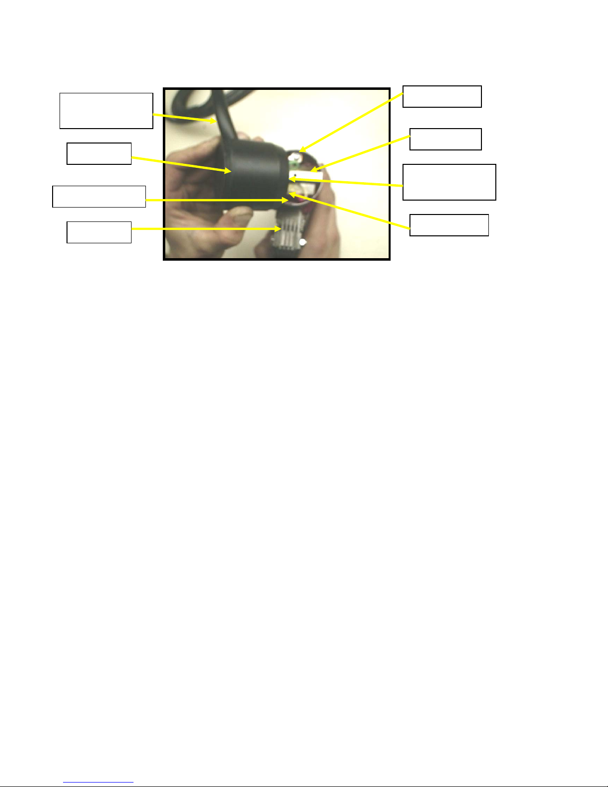
Wiring:
W-Series 230 Volt Models, are designated by a “K” placed after the Serial Number
and the Model number (e.g. WC-6K), are shipped without an AC Power Plug as there
is no international standardization. When installing an AC Power Plug onto the AWG
18-3 Power Cord, the following is the identity of the 3 Color Coded Conductors;
WC-6 Operating Instructions
4