Western Instruments WE-Series User manual

26509 Township Road 543 Phone: (780) 459-6720
Sturgeon County, Alberta Fax: (780) 459-7837
Web: www.westerninstruments.com
Operating Instructions
WE-Series
Standard AC Yokes
WE-Series Operating Instructions
1
WE-3HD
WE-3LT
Established 1965

The WE-Series Products are classified as Standard AC Yokes, which induce a magnetic
field into the ferrous material being tested. These devices should be used within the
parameters set by the operational specifications within this guide.
1. Push Button Switch – The Lycon (#11-304) Micro-Switch is the same style of
switch used in all Standard Yokes (WE-Series and Competitive units). This style of
switch has no grounding provision, so care must be taken by the operator while
performing Wet Method Inspection. The Switch Housings on WE-Series Products
were designed for comfort and safety. While depressed, the switch delivers power
(AC) to the coil encapsulated in the Yoke housing. Review the instructions in this
guide, for switch replacement.
Do not hold the Push Button Switch on when plugging the Yoke into power.
2. Slip-In Switch Cover – The Slip-In Switch Cover is exclusive to WE-Series
Yokes. To remove the cover, simply pinch the cover and pull it out. While the Slip-In
Switch Cover provides superior resistance to moisture ingress than competitive units,
it must be regularly removed to clean the Switch and Housing, during wet method
inspection, in order to avoid operator shocks.
The cover is designed to fit into the cast groove, in only one direction, follow the
Picture below for insertion. Bend the cover longitudinally, and slip the top of the
cover into the grove. Use a small screwdriver to help the bottom of the cover into the
groove after the top is in place.
WE-Series Operating Instructions
2
Switch Housing
Junction Tube
& End Cap
Slip - Switch Cover
Pole Pieces
Target Area
Crack Orientation
Top
Bottom
Wide Side of Switch Cover
Top
Bottom
Helping in Switch Cover
Top Bottom

3. Switch Replacement – Standard Switches (WE-Series or Competitive Units) fail
periodically depending on the Current Draw or Environmental/Service Conditions,
due to an Arc that occurs when the switch is released. These instructions can be
used for all manufactures Products that use a Lycon Series 11 Micro-Switch.
1. Remove the Switch Cover.
2. Using a blunt Chisel or Screwdriver and a hammer, break the plastic switch
housing, and remove the debris.
3. You should be left with the 2 Tabs/Contacts. Using a small pair of pliers, hold the
Tab, and apply heat with your Soldering Iron. The Tab is then easily removed,
and the Core Wires are pre-tined. Take care not to touch the Encapsulant with
your Soldering Iron.
4. Position the new Switch into the Switch Cavity, and press firmly on it. Take care
while soldering the Switch Tabs, not to touch the Encapsulant.
5. Replace the switch cover.
4. Operational Parameters –The Operational Parameters or Duty Cycle for the
operation is set to avoid damage to the internal coil or the Output Module, and must
be observed.
AC Operation: It is recommended that the operator does not keep the Yoke on for
more than 5 minutes at a time, as the Yoke housing may get to warm to hold.
However, the basic design of any Yoke inherently produces heat. Typical operation
is 5 - 15 seconds on, while applying inspection media, followed by 5 - 15 seconds off
for inspection and repositioning the Yoke to the target area.
If the Yoke is used for prolonged periods of time such as 2 to 3 hours of continuous
cycling, as outline above, the Yoke will get warm. If WE-Series Yokes are used in
this manner the operator must provide time for a sufficient cooling period,
DC Operation: When a WE-Series Yoke is connected to a 6 or 12 Volt Battery, for
intermittent use, the operator must be mindful that the Yoke core will produce heat
very quickly. Furthermore, this Battery Power is damaging to the Switch Contacts
and will drastically effect their service life. Under these power conditions, the amount
of time that the Yoke is on should be limited to seconds and not minutes, and the
number of On/Off Cycles should be limited as well. When using DC, Western
WE-Series Operating Instructions
3

Instruments recommends using a 6 Volt DC supply, as the unit will lift 50 Pounds
(over 100 at 12 Volts) and less heat is produced in the Yoke core.
5. Field Characteristics
AC Field – AC Magnetic Fields are sensitive to surface and near surface defects due
to the ‘Skin Effect’ as the magnetic field travels from one Pole Piece to another. The
Inspection Media (Dry Powder or Wet Method Particles) has a tendency to migrate
toward interruptions (or defects) in the magnetic field. The direction and intensity of
an AC Field, by it’s nature, alternates causing high particle mobility, so defects tend
to be revealed immediately when the Media is applied.
DC Field – The Magnetic Field produced with a battery is stronger than an AC Field
and tends to penetrate the work piece more deeply, however DC is still sensitive to
surface defects. Inspection media tends to adhere to the entire target area of the
work piece, due to the lack of particle mobility. Therefore the operator needs to be
careful applying inspection media, and may need to be ‘blown off’ the target area to
fully reveal an indication.
Demagnetization – Small Parts may be demagnetized by positioning the contact
surfaces of the Pole Pieces together, activating an AC Field and pass the part
through the opening formed between the Legs and Yoke Housing. Larger Work
Pieces can be demagnetized by placing the Yoke on the surface, in a similar manner
as used during inspection, activating an AC Field and pull the Yoke off the surface.
The work piece can be tested with a Magnetic Field Indicator, such as the W-Series
W-FI-10®, to ensure it is fully demagnetized.
6. Operation:
Position the Pole Pieces (Feet) on the work piece. The area between the pole pieces
is your target area, which also extends laterally out, approximately 1.5” (38mm), from
either edge of the pole pieces. The Field will expose defects that are transverse to
the centerline between the Pole Pieces. The Pole Pieces should be positioned so
that as much of their contact surfaces as possible, are on the work piece. The Yoke
is then energized, by pressing Push Button Switch, and Magnetic particles are
applied. Dry Method Particles are dusted between the Pole Pieces and over the
target area, while Wet Method Particles are sprayed in a similar manner.
The Target Area is then inspected visually for a collection of Particles around
defects. A Black Light is used to aid visual inspection when Fluorescent Particles are
used. Indications found with Dry Powder will tend to form immediately, and will take
slightly longer with Wet Method Particles. If the typical direction of defects is not
known, rotate the Yoke through 90º and repeat the inspection of the target area.
The WE-Series Yokes produce a standard amount of Field Blow as other AC Yokes.
Field Blow is a collection of Inspection Media between the Pole Pieces, transverse to
the centerline between the Pole Pieces, and may case a masking of indications.
Field Blow can be minimized by extending the Pole Pieces farther apart, If work piece
configuration does not permit extending Pole Pieces, reduce the contact area of the
Pole Pieces on the work piece. Follow the Operational Parameters outlined in these
instructions.
WE-Series Operating Instructions
4

7. Maintenance
After extended use the Yoke should be cleaned with a mild soap solution and
thoroughly dried. The unit should be visually inspected for any damage that could
cause harm to the operator, or the material being inspected. Special attention should
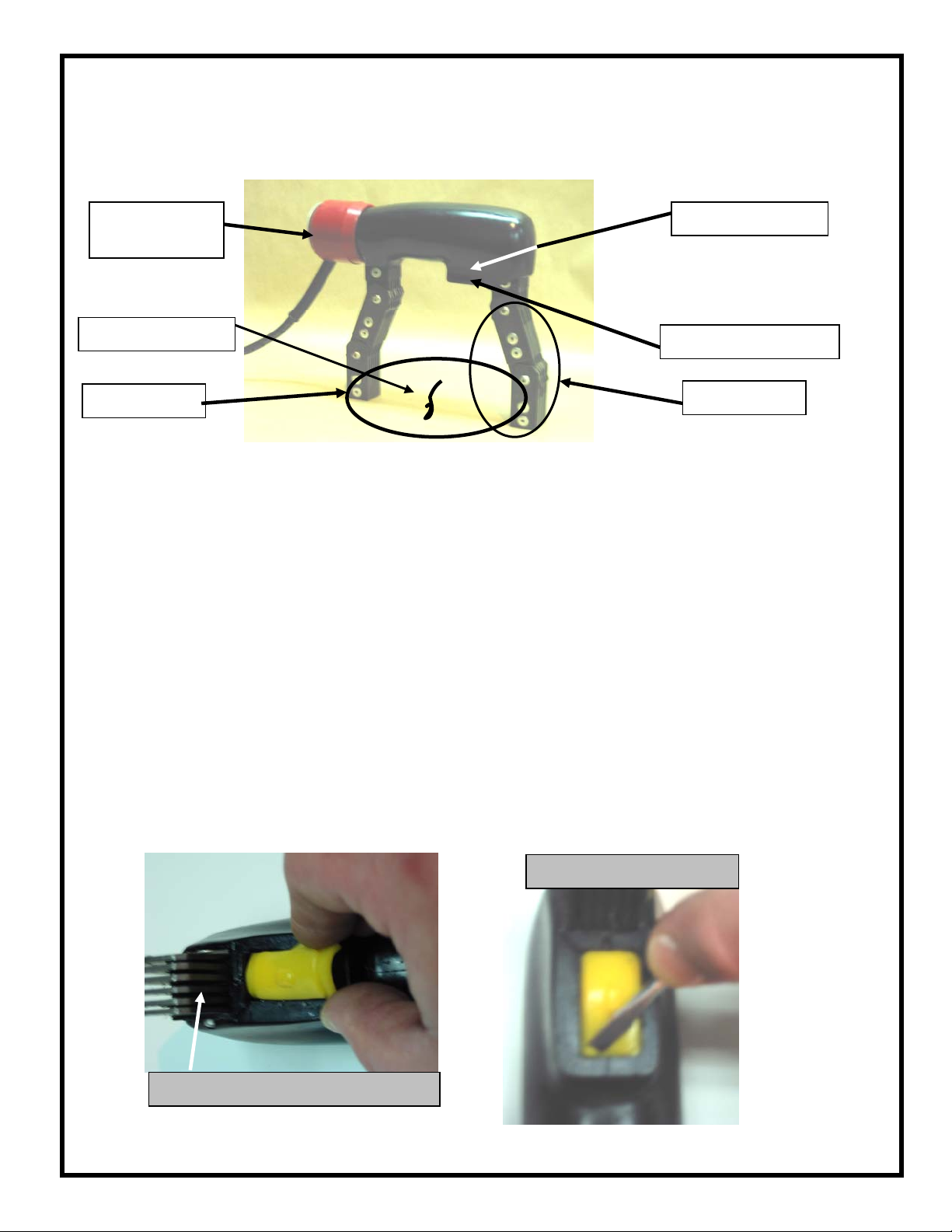
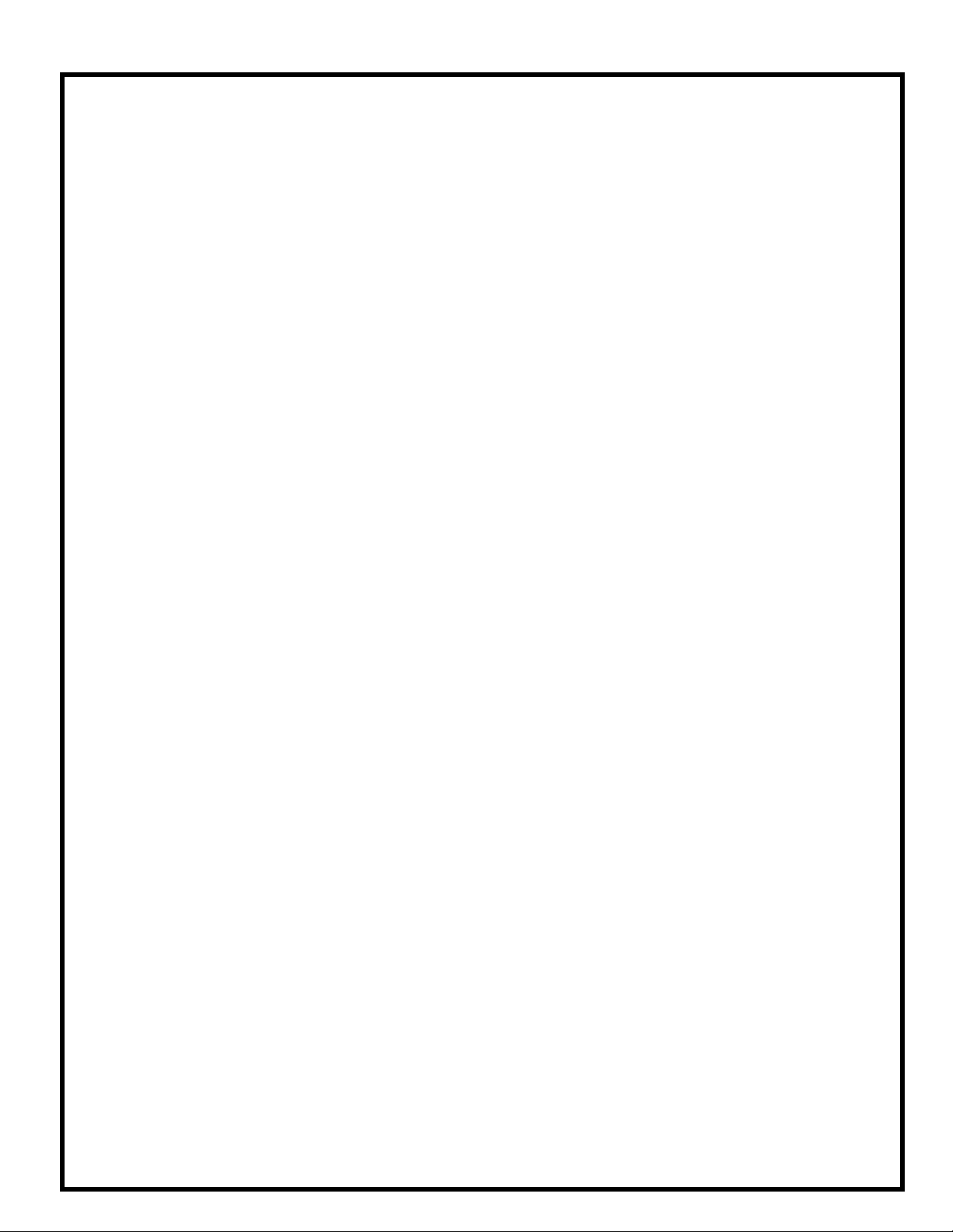
be paid to the Push Button Switch Cover, to ensure it is fully inserted to the groove
cast in the Switch Cavity. The most frequent maintenance issue with any MPI Yoke
is the; Power Plug, Power Cord, and the End Cap/Cord Protector. Attention should
be paid when inspecting these items to ensure they appear in a good state of repair.
Before performing maintenance, cleaning, or repositioning the End Cap. The Yoke
should be disconnected from any power source, with safe industrial practices
employed. Our Web Site has write-up on many of the maintenance issues outlined
above. Any potential problems to these assemblies must be reported to the
Distributor or Western Instruments for instructions on corrective action.
Whether industrial specifications are being observed or not, the Yoke should be
tested periodically, using a certified Pull Test Bar such as the W-Series W-PT®, to
ensure it continues to lift the specified amount of weight. If the unit fails such a test,
first inspect the Pole Pieces to ensure they fully contact the test weight. If the unit
continues to fail, contact the Distributor or Western Instruments for instructions on
corrective action.
Wiring
Western Instruments publishes a Trouble Shooting Guide for WE-Series, and can be
requested by E-Mail upon request. WE-Series Yoke Frames are manufactured in 4
styles; the Standard Frame and the LT Frame, and both frames are available in 115
Volt, and 230 Volt. The Standard frames are black in color, and the LT Frames are
Orange. The only identification distinguishing 115 and 230 Volt frames, is from the
Serial Number; 230 Volt frames have a “K” at the end. As an example, a 230 Volt
frame might have a Serial Number 3490EK, while a 115 Volt unit would be 3490E.
Serial Numbers are indicated on the name plates, but also are stamped onto the
Legs, where they protrude form the casting.
W-Series 230 Volt Models, are designated by a “K” placed after the Serial Number
and the Model number (e.g. WC-6K), are shipped without an AC Power Plug as there
is no international standardization. When installing an AC Power Plug onto the AWG
18-3 Power Cord, the following is the identity of the 3 Color Coded Conductors;
•Green – Ground
•White - Neutral
•Black – Live
Care must be taken to insure the proper installation of an AC Power Plug, and if there
is any question, contact your distributor or Western Instruments. If an AC Plug in not
installed before use, any warranty is void.
8. Pull Test / Calibration
When performing a 10 Pound (4.6Kg) Pull Test, ensure the contact feet are flat as
possible to the Pull Test Bar (W-PT®), which ensures as much magnetic attraction as
possible. While not particularly important on Full Size Yokes (WE-3 & HD units), it is
very necessary on the WE-3LT due to the flexibility of the Pole Pieces. If a Yoke fails
a pull test, it should be sent to an authorized repair facility for Contact Foot Dressing.
WE-Series Operating Instructions
5

Warranty
Western Instruments warrants its products, against defects in materials and workmanship for
a period of 1year from receipt by the end user. If Western Instruments receives notice of such
defects during the warranty period, Western Instruments will either, at it’s option, repair,
replace, or condemn products that prove to be defective. Consumable items, such as
Batteries are warranted for 30 days, from receipt by the end user.
Any warranty is void if the unit has been modified in any way, or if it has been repaired by an
unauthorized agency. The end user agrees that any equipment’s disposition, when returned
for warranty work, is at the full discretion of Western Instruments as to whether a claim is
under warranty, or due to misuse. Western Instruments warranty shall overlook normal wear,
however does not include operation outside the environmental specification of the product. All
warranty work is FOB Western Instruments, and any returned units shall include a written
description, by the end user, of the fault.
Western Instruments makes no other warranty, either expressed or implied, with respect to
this product. Western Instruments specifically disclaims any liability arising form the use of
this equipment. For the correct use of the product, refer to the Operating Instructions,
furthermore we recommend instructional training to CGSB, ASNT, or other regulatory
authority qualifications. Western Instruments highly recommends the end user exercise all
possible safety precautions, including use of protective equipment, while operating this or
other industrial equipment.
Specifications:
Model: WE-3 or WE-3K
WE-3HD or WE-3HDK
WE-3LT or WE-3LTK
Voltage: 115VAC or 230VAC / 6 or 12 VDC Intermittent.
Frequency: 50 or 60 Hz
Current: 4.0 Amps @115 Volts x 60 Hz
2.0 Amps @230 Volts x 50 Hz (K Designation)
Capacity: <10 Pounds (4.6 Kg) in AC
<50 Pounds (23 Kg) at 6 Volts DC
Pole Spacing: 0 – 11” (0 – 280mm)
Weight: 6.5 Pounds (3.0 Kg) / WE-3LT: 5 Pounds (2.3Kg)
Phone: (780) 459-6720
Fax: (780) 459-7837
WE-Series Operating Instructions
6
E-mail: Info@westerninstruments.com Web: www.westerninstruments.com
This manual suits for next models
2
Table of contents
Other Western Instruments Test Equipment manuals
Popular Test Equipment manuals by other brands

GESTRA
GESTRA VKP 42 Ex Original Installation Instructions

Pasco Scientific
Pasco Scientific ME-8950 Instruction manual and experiment guide

JDS Uniphase
JDS Uniphase IP Video Test Option HST-3000 Testing Guide

Tektronix
Tektronix TDS1001B Security instructions

Elma Instruments
Elma Instruments ELMA 46 manual

Pittway
Pittway S300PTU user guide