2
TABLE OF CONTENTS CONDITIONAL WARRANTY
Western Shelter Systems warrants all
products against defects in materials or
workmanship for a period of one (1) year
from date of manufacture. Component
manufacturers’ warranties may exceed that
of Western Shelter.
No warranty is made or implied regarding
the intended use of the product. Warranty
does not cover damage caused by abuse,
misuse, neglect or improper care by the end
user in the application of the Western Shelter
Systems product.
Western Shelter Systems will repair or
replace any component deemed to be faulty
from manufacture in the most ecient and
timely means available to Western Shelter
Systems.
Western Shelter Systems must authorize all
claims prior to any action taken by the end
user.
For immediate attention regarding any
defective product, please phone Customer
Support at 1-800-971-7201, 7am-330pm PST.
Shipping: 815 Conger St. Eugene, OR 97402
PO Box 2729 Eugene, OR 97402 USA
Phone 1-541-344-7267
Toll Free 1-800-971-7201
Fax 1-541-284-2820
www.WesternShelter.com
A. Warnings 3
B. Shelter Specications 4
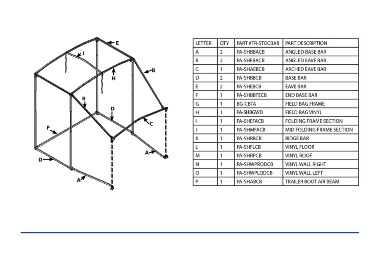
C. Component List 4
D. Erecting the Shelter 5
1. Unpacking the Shelter 6
2. End Frame Assembly 6
3. Center Frame Assembly 6
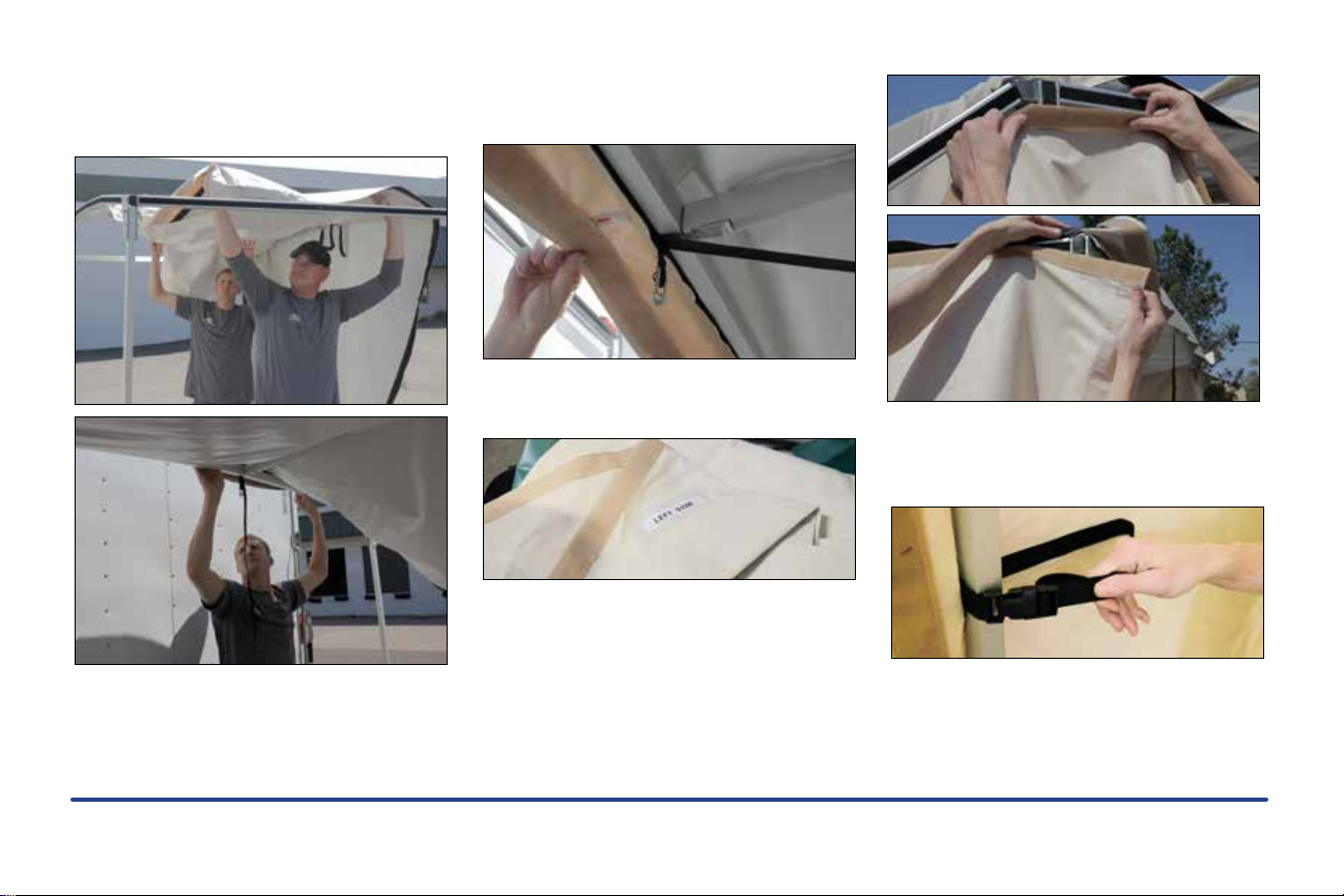
4. Roof Assembly 7
5. Raising the Frame 8
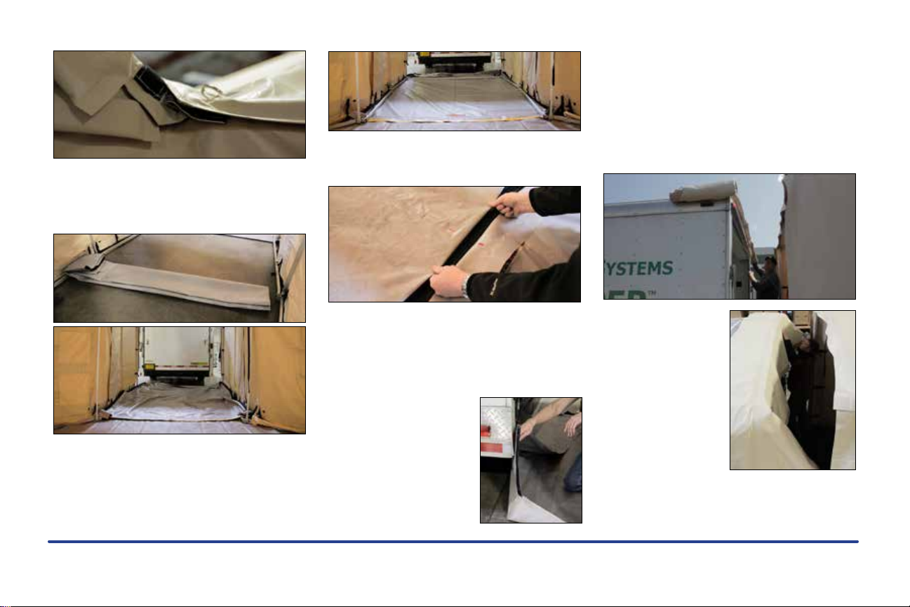
6. Floor and Basebars 8
7. Hanging the Doors 9
8. Hanging Shelter Walls 9
9. High Wind Tiedowns 10
10. Finishing the Shelter 11
E. Striking the Shelter 12
1. Removing Wall Panels 12
2. Folding Wall Panels 12
3. Folding Floor Panels 13
4. Lowering the Frame 14
5. Removing Vent Caps 14
6. Folding Roof Panels 14
7. Striking the Frame 16
F. Troubleshooting 17
1. Frame Connections 17
2. Wall Panels 17
3. Roof Panels 17
4. Torn or Worn Vinyl 17
5. Parts will not t in case 17
G. Tips, Care, and Repair 18
1. Vinyl Panels 18
2. Insulation Panels 18
3. Mainframe and Bars 18
4. Hinges and Pull-Pins 18
5. Cases and Lids 18
6. Vinyl Repair 19
7. Replacement Parts 19