VEHICLE RECOVERY ELECTRIC WINCH FITTING INSTRUCTIONS
T-MAX
UTV SERIES
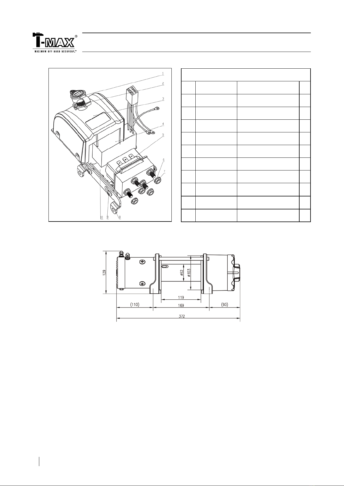
EXPLODED VIEW OF ATW4500
Item Part No. Description Qty
1 GB/T70 M6×120 Bolt M6 X 120 2
2 7241100.1.3-2 Motor End Cover 1
3 7241100.1.1.3.1 Carbon Assy 1
4 7241100.1.1 Stator 1
5 7241100.1.2 Rotor 1
6 GB/T-85 M6×18 Bolt M6X18 4
7 7241100.1-1 Motor Frame Cover 1
8 7241100.3-1 Drum Base 2
9 7241100.8 Torque Limiter 1
10 GB/T276-1994 Bearing 2
11 7241100.2 Drum 1
12 7241100.0-1 Tie Rod 2
13 7241100.3-9 Sun Gear 1
14 7241100.0-3 Spring 1
15 7241100.8-7 Washer 1
16 7241100.3-3 Inner Gear- Output 1
17 7241100.5 Braking System 1
18 7241100.3.1-4 Gear Spindle 3
19 7241100.3.1-1 Gear Carrier 2
20 GB/T276-1994 61812 Bearing 2
21 7241100.3.1-3 Planetary Gear 3
22 7241100.3-4 Anti-friction Gasket 1
23 7241100.3-5 Inner Gear 1
24 7241100.3-8 Clutch Yoke 1
25 7241100.3-7 Inner Lock washer 1
26 7241100.3-2 Gear Box Tube 1
27 GB/T3452.1 23.6×1.80 O Ring 1
28 7241100.3-6 Clutch Cover 1
29 7241100.0-2 Mounting Plate 1
30 GB/T5782-2000 M8×20 Bolt M8 X20 2
31 7241100.4 Roller Fairlead 1
32 7241100.7 Wire Rope 1
33 RU104206 Clevis Hook 1
34 7309200.7-2 Aluminum Fairlead 1
35 9163151 Synthetic Rope 1
36 7241100.6-1 Short Black Cable (10mm2 x 5cm) (wrapped by Black
Thermoplastics Pipes) 1
37 7241100.6-2 Short Black Cable (10mm2 x 10cm) (wrapped by Red
Thermoplastics Pipes) 1
38 7241100.6-3 Short Black Cable (10mm2 x 12cm) (wrapped by Yellow
Thermoplastics Pipes) 1
39 7241100.6.2 (W) Control for ATV Use (match to Wire Rope) 1
7241100.6.2 (S) Control for ATV Use (match to Synthetic Rope) 1
40 7241100.6.4 Socket Assy 1
41 7241100.6-4 Long Cable (10mm2 x 180cm) 1
42
7241100.6.3 (W) Remote Handle Control for UTV & Utility Use (match to Wire
Rope) 1
7241100.6.3 (S) Remote Handle Control for UTV & Utility Use (match to
Synthetic Rope) 1
43 7241100.6.4 (W) Control Box Assy(match to Wire Rope) 1
7241100.6.4 (S) Control Box Assy (match to Synthetic Rope) 1
44 7241100.6.1 ISM 1
3