Wexxar BEL 290 Installation and operating instructions

OPERATION &SERVICE MANUAL 65-35-1 Effective February 26, 2010
BEL 290
FULLYAUTOMATIC TOPAND BOTTOM
CASE TAPE SEALER
Wexxar Packaging Inc.
Phone (604) 930-9300 • Fax (604) 930-9368
Rev 1.1

BEL 290 FULLY AUTOMATIC CASE TAPE SEALER 2
SAFETY CAUTION
Ensure that the machine is disconnected from air and power supplies before undertaking
any maintenance or service procedures.
The machine must be operated by qualified personnel only.
0
2
9
Standard Specifications:
Length Width Height
Case Size Range Minimum 6” / 152 mm 5” / 127 mm 5” / 127 mm
Maximum 22” / 559 mm 18” / 457 mm 19” / 483 mm
Machine Dimensions 79” / 2008 mm 39” / 987 mm 62” / 1575 mm
In/Outfeed Height Frame 22.3” / 563 mm
With adjustable leg extensions
[foot pad] Minimum
Maximum
24.5" / 622 mm
32” / 813 mm
Speed Up to 32 cases / min.
Shipping Weight Approx. 950 lbs. / 430 kg.
For further detail, see Layout Drawing 75-776
65-35-1 02/26/10

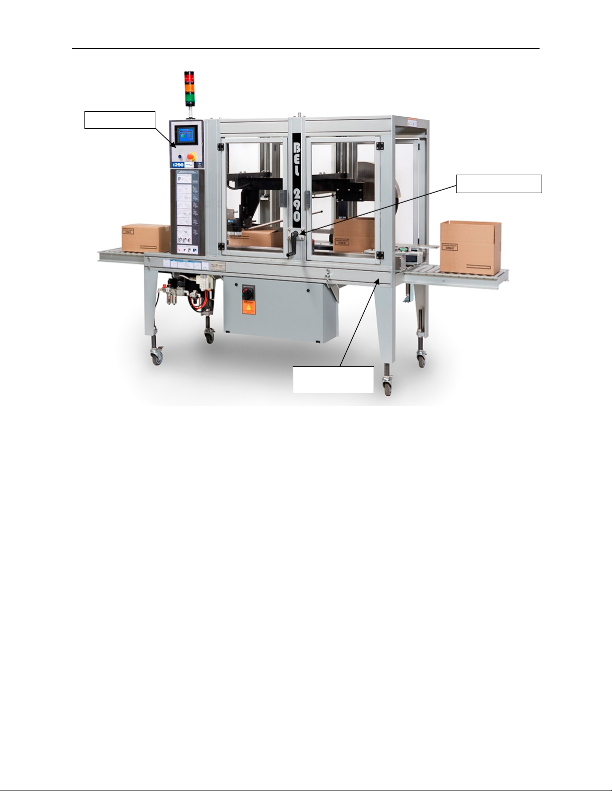
BEL 290 FULLY AUTOMATIC CASE TAPE SEALER 3
TABLE OF CONTENTS
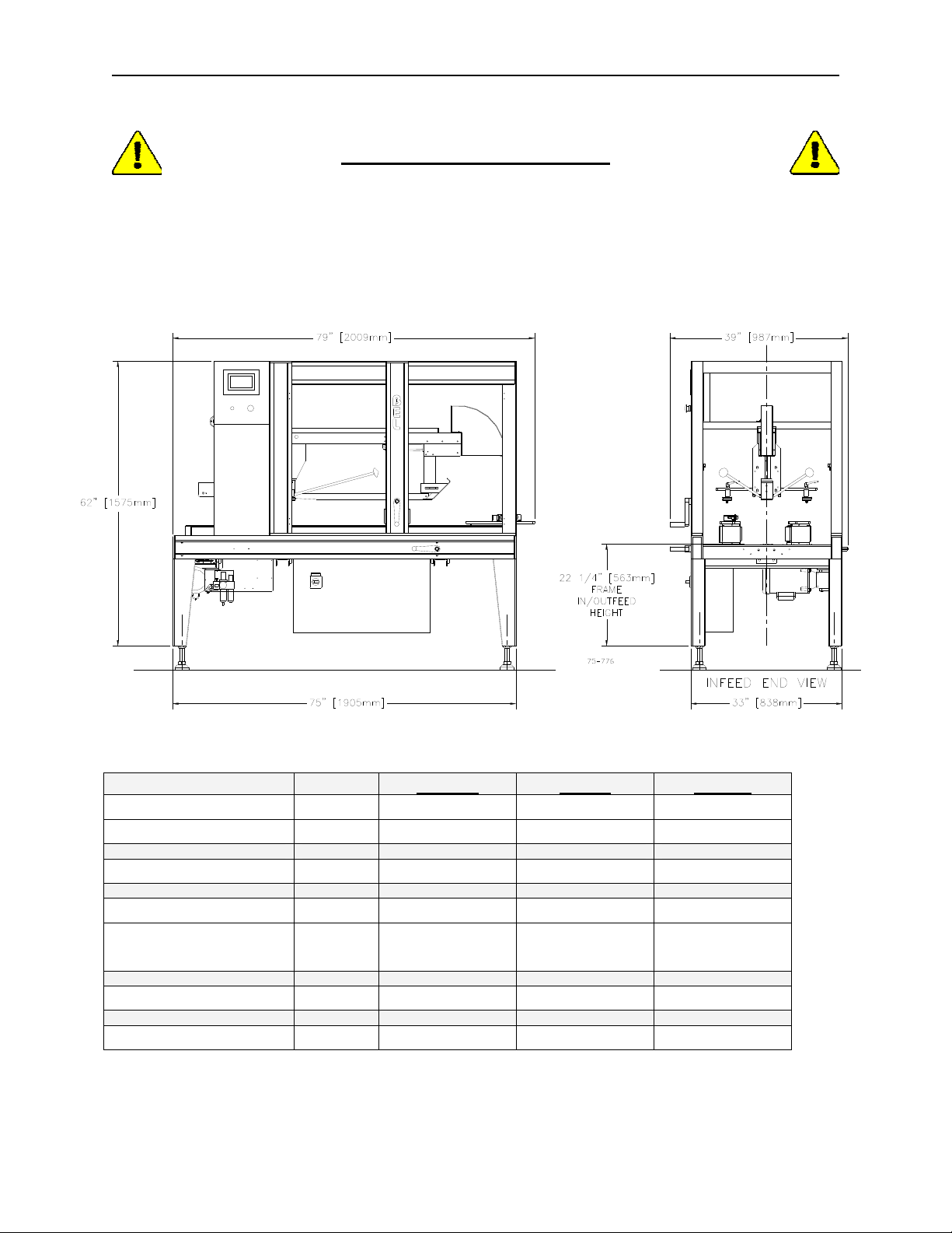
INSTALLING THE BEL 290.....................................................................................................................................4
LEVELING THE MACHINE...........................................................................................................................................4
INSTALLING THE TAPE HEADS ..................................................................................................................................5
POWER CONNECTIONS.............................................................................................................................................5
Electric ................................................................................................................................................................5
Compressed Air.................................................................................................................................................5
MACHINE ADJUSTMENTS......................................................................................................................................6
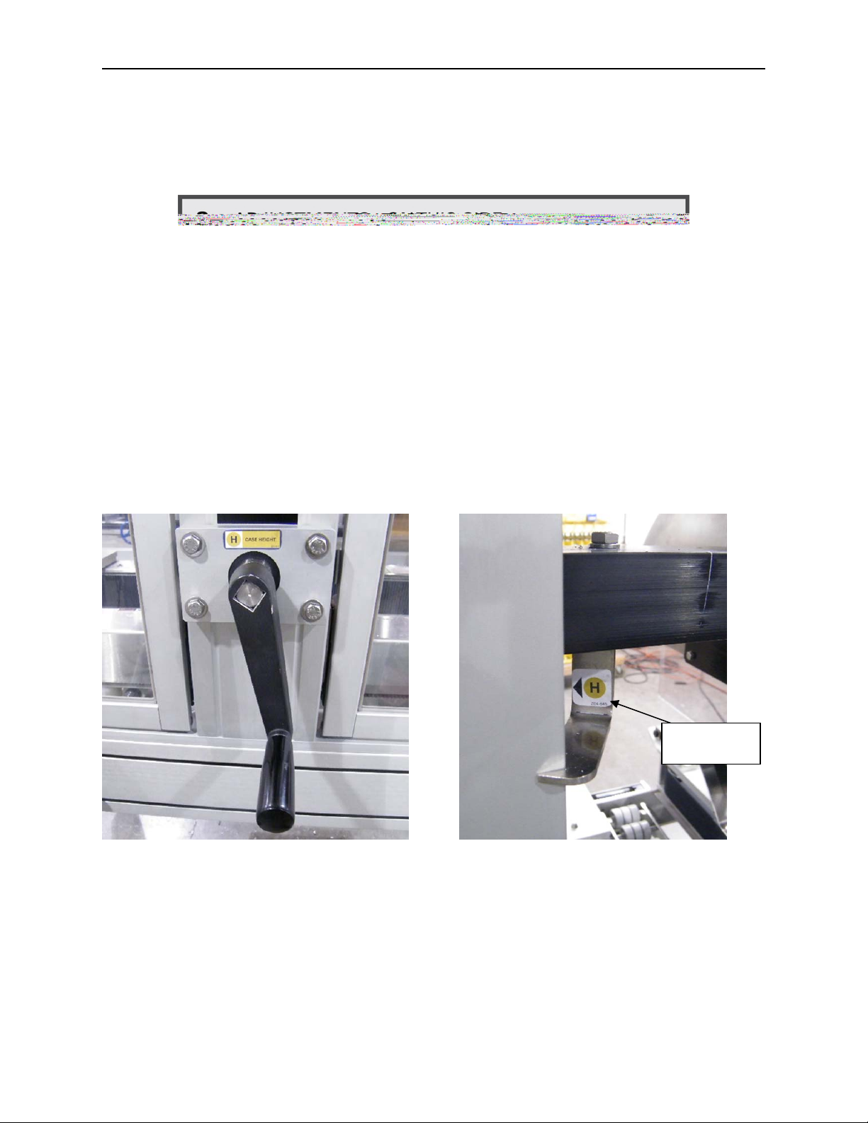
CASE HEIGHT ADJUSTMENT.....................................................................................................................................7
Case Dimension ‘H’ Adjustment......................................................................................................................7
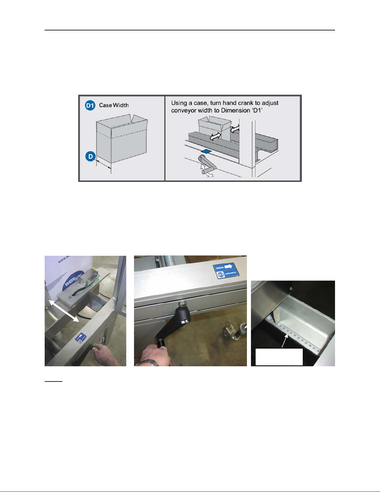
CASE WIDTH ADJUSTMENT ......................................................................................................................................8
Case Dimension ‘D1’ (Conveyor Adjustment)...............................................................................................8
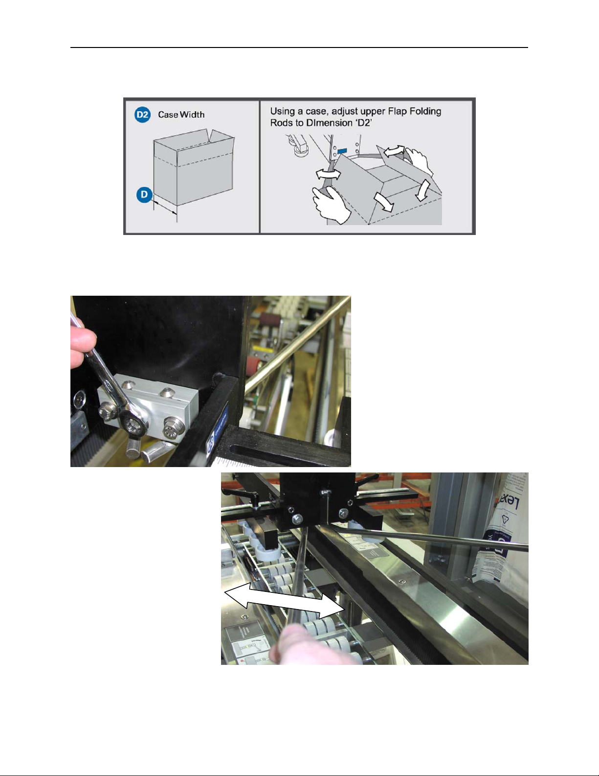
Case Dimension ‘D2’ (Major Flap-folding Rods) ..........................................................................................9
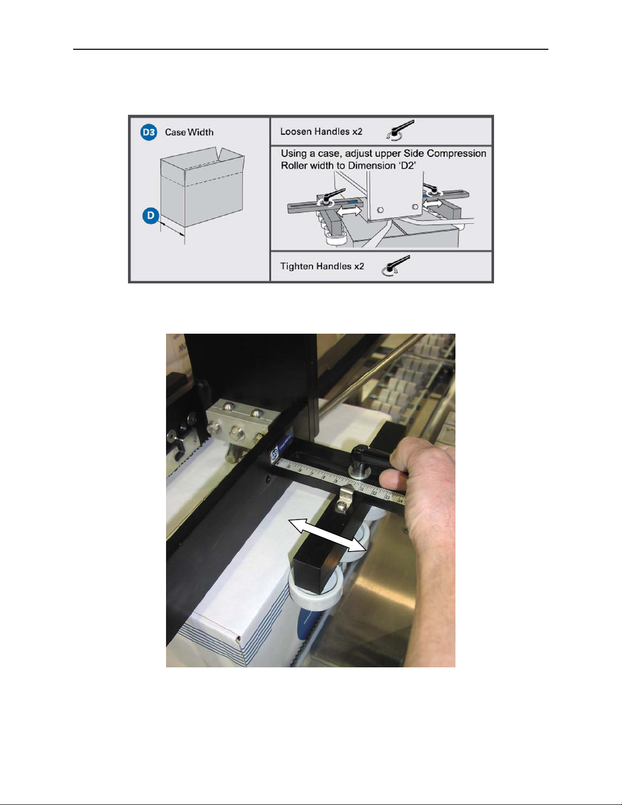
Case Dimension ‘D3’ (Case Side Compression)........................................................................................10
TOP SKI FLAP WIDTH ADJUSTMENT ‘G’.................................................................................................................11
STARTING THE MACHINE....................................................................................................................................12
COMPRESSED AIR ..................................................................................................................................................12
ELECTRICAL SWITCHING ........................................................................................................................................13
CONTROLS...............................................................................................................................................................14
CONTROLS OVERVIEW ...........................................................................................................................................14
CONTROLS DESCRIPTION.......................................................................................................................................15
FEEDING CASES INTO THE MACHINE.............................................................................................................26
STOP GATE (OPTION).............................................................................................................................................26
SERVICE AND MAINTENANCE PROCEDURES..............................................................................................27
EQUIPMENT SAFETY...............................................................................................................................................27
PREVENTIVE MAINTENANCE...................................................................................................................................28
Weekly Inspection...........................................................................................................................................30
Monthly Inspection..........................................................................................................................................30
SIDE-BELT CONVEYOR SYSTEM.............................................................................................................................31
Chain Drive Tension .......................................................................................................................................32
Gear Reducer...................................................................................................................................................32
Side-belt Replacement...................................................................................................................................33
TROUBLESHOOTING GUIDE...............................................................................................................................36
SECTION 1-CORRUGATED CASE QUALITY &SPECIFICATIONS............................................................................36
SECTION 2-CONVEYOR BELT SYSTEM.................................................................................................................37
SECTION 3-GENERAL TAPING CONDITIONS.........................................................................................................39
SECTION 4-CASE INFEED .....................................................................................................................................40
MACHINE CONTROLS..............................................................................................................................................41
65-35-1 02/26/10

BEL 290 FULLY AUTOMATIC CASE TAPE SEALER 4
Control Panel
Case Height Crank
Note: Position of HMI
panel and control
panel may vary
according to order
specifications
Case Width Crank
(not shown here)
BEL 290 fully automatic top and bottom taper
Installing the BEL 290
1. Remove the through-bolts that secure the machine to the shipping base.
2. If possible, use a forklift to move machine off its base, with wooden blocks between the forks
and the frame.
3. While machine is elevated, install the footpad extensions or castor extensions to the bottom
of each leg and adjust them for the desired operating height.
4. Position the machine where it is to be used.
LEVELING THE MACHINE
The machine should be installed in a level position to avoid frame stress and ensure optimum
performance. An adjustable height footpad kit is included as standard equipment and can be
used to level the machine on an uneven floor.
The machine should be anchored to adjoining equipment or the floor to prevent any movement
of the machine by reactive forces that may occur as sealed cases are being driven through the
machine outfeed.
65-35-1 02/26/10

BEL 290 FULLY AUTOMATIC CASE TAPE SEALER 5
INSTALLING THE TAPE HEADS
Tape dispensing heads are mounted using the pins on their sides. These pins fit into
corresponding slots in the upper and lower tape head mounting brackets. Machines are usually
shipped with the tape heads secured in their brackets. To reinstall the tape heads, lower them into the
brackets to align the pins on their sides with the slots in the brackets. Follow these steps:
1. On the bottom tape head, slide the rear pins on the head down and back into the ‘key’-
shaped slots. The front pins will then drop into vertical slots of the bracket. The head is
held in place by its own weight.
2. On the top tape head, both the front and rear pin heads engage the key-shaped slots in the
tape head mount. Push the top head back in its holder to secure it between spring-loaded
retainers so that it will not move out of position.
Please consult the tape head manual for instructions on the mounting of tape rolls and the
proper threading of tape through the applicator head.
POWER CONNECTIONS
Electric
The BEL 290 is equipped with single phase 110-120 VAC electrics to and manufactured NEMA
12 specifications. A 1/2 horsepower TEFC motor that draws eight amps powers the drive
system. A minimum AWG 14 gauge power extension cord with standard three-pin connection
must be used to connect the machine to the power source.
If any electrical connections are needed to install the machine, they must be handled by a
qualified electrician in your jurisdiction.
Compressed Air
The BEL 290 requires an air supply, which must be clean and dry, with a PSI between 80 and
120 and an optimal pressure of 90 PSI. The kicker regulator must always be set at 70 PSI. The
volume of air required for the BEL 290 is rated at 0.1 C.F./cycle at 90 PSI. (6 Bar). The
incoming air supply line must be of sufficient diameter to provide an adequate amount of air
without pressure drops when the machine is cycling. A 1/2” air line size is recommended.
One of the most common causes of inconsistent machine performance is inadequate air supply.
Therefore, meeting machine air requirements is important to assure satisfactory operation.
The BEL 290 is equipped with an electric air ‘ON/OFF’ valve, an air filter/regulator and second
coalescing filter which should be checked periodically to ensure that the air pressure is
regulated to the proper setting, and that the filters are not contaminated.
PLEASE NOTE:
Best performance with BEL machines will occur when the machine is adjusted, operated and
maintained in accordance with the instructions in this manual. We cannot be responsible for
unauthorized changes to the machine or methods of its operation.
The following information is a reference guide for our standard machines. We strive to provide
up-to-date manuals with machines but we are continually improving our products, and the details
in the manual provided might not exactly match the machine at the time it is shipped. Many
machines are modified in response to customer requests or as required by the case samples
supplied at the time the machine is built, so the manual may not provide a complete reference to
the changes or modifications. If there are any questions about your machine not covered by the
manual, please contact us and we will do our best to provide the additional information you
need.
65-35-1 02/26/10

BEL 290 FULLY AUTOMATIC CASE TAPE SEALER 6
Machine Adjustments
Safety:Disconnect machine electrics and compressed
air before making any machine adjustments.
There are only two main, quick adjustments required in setting up the BEL 290 to run a
particular case size:
1. Case width adjustment ‘D’- Use the hand crank on the side of the bottom frame
to move side-belt conveyors in and out to fit the width of the case.
2. Case height adjustment ‘H’- Use the side hand crank on the top guarding frame
to vertically adjust the machine head with the top flap folders and tape head to match
the height of the closed case.
D D
E
120-093
H
In practice, it is best to first open up the adjustments first to fully clear the height and width of
case.
65-35-1 02/26/10

BEL 290 FULLY AUTOMATIC CASE TAPE SEALER 7
CASE HEIGHT ADJUSTMENT
Case Dimension ‘H’ Adjustment
Use the case height crank and scale on the side of the arch to adjust the case height to
Dimension ‘H’.
CASE HEIGHT
SCALE ‘H’
65-35-1 02/26/10

BEL 290 FULLY AUTOMATIC CASE TAPE SEALER 8
CASE WIDTH ADJUSTMENT
Case Dimension ‘D1’ (Conveyor Adjustment)
Use the case width crank and the scale at the front of the conveyor to set Dimension ‘D1’. The
case width crank can be connected to the case width leadscrew on either side of the machine
frame.
An alternative method to using the width scale is first to move the conveyor belts apart until they
are wider than the case to be run. Then, adjust the conveyor belts back in until they lightly
contact the case sides. Remove the case through the machine infeed and wind the belts in by a
further one-half turn. This usually moves the conveyor to the correct position for a good grip on
the case.
CASE WIDTH
SCALE
Note: Depending on case fill, weight, dimensional variations, and conveyor belt wear, it may be
necessary to make minor adjustments to the settings to ensure best performance.
65-35-1 02/26/10

BEL 290 FULLY AUTOMATIC CASE TAPE SEALER 9
Case Dimension ‘D2’ (Major Flap-folding Rods)
If necessary, loosen the bolts that lock the top major flap folding rods in position and adjust their
position so that they capture the top case flaps and fold them down ahead of the top tape head
as the case passes under them. The rods will need to be moved inward toward each other for
narrow cases and outward for wide ones.
65-35-1 02/26/10

BEL 290 FULLY AUTOMATIC CASE TAPE SEALER 10
Case Dimension ‘D3’ (Case Side Compression)
Adjust the side-compression rollers to control the tendency of the upper sides of the case to
expand due to incorrect top flap folding and perhaps case overfilling. The side-compression
rollers should minimize the gap between the top major flaps while they are being taped.
65-35-1 02/26/10

BEL 290 FULLY AUTOMATIC CASE TAPE SEALER 11
TOP SKI FLAP WIDTH ADJUSTMENT ‘G’
The top ski, used to fold down the front minor flap, is mounted on a slotted bracket that permits
the ski to be adjusted towards or away from the machine infeed. Unless there is a wide
variation in the width of cases or the size of case minor flaps, it should not require frequent re-
adjustment.
Ski position must allow rear minor flap to fold down without hitting the
ski, but once folded, also hold the flap down and not let it re-open.
The flap width is
usually 1/2 of the
case width.
The size of the case minor flap, which, with RSC cases, usually is a function of case width,
determines the adjustment. When running cases that are close to the machines minimum and
maximum width limits, or cases with different flap lengths (i.e. Flap-cut cases) it may be
necessary to adjust the position of the ski to keep control of the minor flaps.
•To run most case widths close to the machine’s average width capabilities, the ski
should be set at the midpoint on its mounting slot.
•With cases that are close to the maximum machine width capability, or with larger than
normal minor flaps, the ski should be adjusted back, away from the machine infeed so
that the rear minor flap does not hit the ski before it is fully folded down.
•With cases that are near the machine minimum width capability, or with narrower than
normal minor flaps, the ski should be adjusted forward, towards the machine infeed, so
that the rear minor flap is guided underneath the ski and does not spring open before it
reaches the ski.
65-35-1 02/26/10

BEL 290 FULLY AUTOMATIC CASE TAPE SEALER 12
Starting the Machine
COMPRESSED AIR
There is a manual air ‘ON/OFF’ valve located where the air supply is connected to the machine
at the filter-regulator unit and it must be in the ON position to supply air to the machine circuit.
In addition, there is an air supply solenoid valve operated by the electrical machine controls.
Manual ‘ON-OFF’ Lockout valve
shown in the OFF position with
the padlock mounting holes
ali
g
ned.
Air Supply
Solenoid Valve
Manual ‘ON/OFF’ air
su
pp
l
y
valve
Kicker
Regulator
65-35-1 02/26/10

BEL 290 FULLY AUTOMATIC CASE TAPE SEALER 13
Ensure that the machine's main air solenoid valve is shut OFF before attempting to clear jams
or make minor adjustments which require you to get close to the moving parts of the machine.
This air valve shuts off when the ‘EMERGENCY STOP’ button is activated, guard doors are
opened or when the main power is switched OFF.
To carry out service or repair work safely on the machine, the manual air ‘ON/OFF’ valve is
located on all WEXXAR machines upstream of the filter-regulator unit. Padlock this valve in the
OFF position for absolute safety during service work. Always follow local lock-out/tag-out
regulations.
Always exercise caution when switching the compressed air back ON. Stay well clear of all
moving parts, as they may move quickly when the pressure is reapplied. Make sure that no
other people are in a dangerous position when switching the compressed air ON. When the
valve is turned to the OFF position, air pressure in the machine circuit is exhausted.
Electrical Switching
A ‘MAIN DISCONNECT’ switch is located on the lower control panel Switch on the electrical
supply to power the machine programmable logic controller [PLC] and control screen [HMI].
They with then go through their startup cycles and be ready for machine operation.
The lockable ‘MAIN DISCONNECT’ switch should be OFF and locked before service work is
attempted outside of the control enclosure. Before performing service work inside of the control
enclosure, disconnect all electrical power to the machine (either by unplugging the supply cord
or switching OFF a separate customer-supplied disconnect).
The main supply voltage is typically 120V 60Hz single phase, but alternate voltages are available
to meet specific customer requests.
65-35-1 02/26/10

BEL 290 FULLY AUTOMATIC CASE TAPE SEALER 14
Controls
Control Panel with
Touchscreen Interface
CONTROLS OVERVIEW
The control system consists of a touchscreen interface and a Programmable Logic Controller
(PLC), which interact with each other and make the machine operate. The machine controls
manage all machine operations. The screen interface provides operator control of the machine
through software ‘pushbuttons’ displayed on the screen. It also provides instructions related to
machine operation.
This section lists the standard controls on a BEL 290. Actual control functions may vary
depending on options installed on your machine. Pay special attention to the location of the
‘EMERGENCY STOP’ button, the ‘RESET’ button, the ‘MAIN DISCONNECT’ and pneumatic
‘ON/OFF’ valves.
65-35-1 02/26/10

BEL 290 FULLY AUTOMATIC CASE TAPE SEALER 24
28) ‘PLC INPUTS’ Button
In the center-left side of the ‘Troubleshooting’ screen is the
‘PLC INPUTS’ button. Touch this button to access the ‘PLC
Inputs’ screen.
‘PLC INPUTS’
Button
29) ‘PLC Inputs’ Screen
The ‘PLC Inputs’ screen displays 24 function indicators, for 24
machine functions. If one of the 24 machine components is not
functioning, the corresponding indicator will be flashing on and
off. Note that the function indicators are not buttons. They are
not touch-sensitive. Touch the ‘PREVIOUS’ button in the
bottom right-hand corner of the screen to return to the
‘Troubleshooting’ screen, or touch the ‘MAIN CONTROL’
button in the bottom left-hand corner of the screen to bring up
the ‘Main Control’ screen.
‘PLC INPUTS’
Status Indicator
‘PLC Inputs’ Screen
65-35-1 02/26/10

BEL 290 FULLY AUTOMATIC CASE TAPE SEALER 25
30) ‘PLC OUTPUTS’ Button
In the center-right side of the ‘Troubleshooting’ screen is the ‘PLC
OUTPUTS’ button. Touch this button to access the ‘PLC Outputs’
screen.
‘PLC OUTPUTS’
Button
‘PLC Outputs’ Screen
31) ‘PLC Outputs’ Screen
The ‘PLC Outputs’ screen displays sixteen buttons. Each of these
output buttons controls a PLC output directly. To test these functions,
stop the machine and remove any unformed cases from the magazine.
Then touch each button. When a button is touched, it will illuminate and
that machine component will function. If it does not function, inspect and
repair the component. Touch the ‘PREVIOUS’ button in the bottom right-
hand corner of the ‘PLC Outputs’ screen to return to the
‘Troubleshooting’ screen. Touch the ‘MAIN CONTROL’ button in the
bottom left-hand corner of the screen to bring up the ‘Main Control’
screen.
‘PLC OUTPUTS’
Status Indicator
65-35-1 02/26/10

BEL 290 FULLY AUTOMATIC CASE TAPE SEALER 26
Feeding Cases into the Machine
A powered infeed conveyor belt is the preferred method of feeding cases to the BEL 250
although gravity or manual feed may also be used. For powered conveyor infeed, a speed of 60
FPM or less is recommended.
STOP GATE (OPTION)
Stop gate shown in the up
or closed position
The BEL 290 can be equipped with an optional timed stop gate that separates the cases as they
enter into the machine.
65-35-1 02/26/10

BEL 290 FULLY AUTOMATIC CASE TAPE SEALER 27
Service and Maintenance Procedures
EQUIPMENT SAFETY
The BEL 290 has safety features to prevent you from injury while maintenance is in progress.
Sliding and bi-folding guard doors, equipped with interlock switches, are in place to prevent you
from entering the work cell while the case forming is in progress; the machine will not run if
these doors are open. The access door of the control enclosure also has to be closed for the
machine to operate.
The perimeter guarding system surrounds the area known as the restrictive envelope and
covers the entire range of possible machine motion. For your safety, you should never try to
bypass the perimeter guarding system or enter the restrictive envelope while the machine is in
operation.
The ‘EMERGENCY STOP’ button immediately halts all machine operation by cutting off air
supply and electrical power. This button should be pushed IN to stop the machine in case of an
emergency.
Precautions
•Do not use flammable or toxic fluids such as gasoline, benzene, or ether to clean the
equipment.
•Do not use liquids other than those listed when performing maintenance on the machine.
•Use the appropriate lubricants when lubricating the machine.
Applicable Laws
•Before adjusting, maintaining, or cleaning this machine, disconnect the power and lock
out according to local regulations.
The BEL 290 Case Sealer is equipped with safety interlocks. Do
not attempt to disable or bypass the safety interlocks or any other
safety features when operating the machine.
Always follow the specified procedure when making machine adjustments.
65-35-1 02/26/10

BEL 290 FULLY AUTOMATIC CASE TAPE SEALER 28
PREVENTIVE MAINTENANCE
A regular program of preventative maintenance will help to avoid unnecessary downtime due to
premature component failures.
Daily Inspection
A careful daily inspection of the machine will often catch problems when they are minor and easily
corrected and prevent costly breakage of parts. On a daily basis, the operators should inspect:
1. Pneumatic system: With the machine air OFF, inspect all pneumatic motions for smooth
action without excessive bearing wear. If all is okay, switch the machine ON and observe
carefully as it processes a case, listening for signs of air leakage or other abnormal noises.
All mechanical actions should be smooth and free of shock at the end of the motion.
2. Conveyor belts: Carefully observe the conveyor belts, and watch for signs of uneven wear
(edge fraying) which can occur if a belt is not tracking centrally. Correct any such uneven
tracking by tightening the tensioner on the side which the belt moves towards. Watch for
signs of improper belt tensioning, such as the belts slipping when transporting a heavy
case.
3. Gear reducers: Observe the gear reducers for signs of oil leakage. If oil leakage occurs,
check the oil level by removing the oil level plug to ensure that the correct oil quantity is
present. Top up if necessary.
4. Filter bowl: Regularly check the pneumatic filter bowl and filter for water and debris;
replace the filter at suitable intervals, depending on the cleanliness level of the incoming air
supply. A drain is fitted to vent water automatically from the filter bowl. If necessary, clean
the filter bowl with soapy water.
5. Fasteners: Inspect the machine’s fasteners. Tighten any which have become loose. It is
advisable to apply blue colour Loctite 242 (blue) thread locker to the screw threads to
prevent loosening.
6. Kicker: Inspect for correct bolt tightness. Listen for banging sounds during operation.
7. Stop gate: Inspect for correct bolt tightness. Listen for banging sounds during operation.
8. Noise: Listen for any irregular noises or signs of machine wear. All mechanical actions
should be smooth and free of shock at the end of the motion.
65-35-1 02/26/10

BEL 290 FULLY AUTOMATIC CASE TAPE SEALER 29
Daily Inspection
Inspect all pneumatic motions for smooth action and belt wear.
As the machine processes a case, listen for air leakage or other abnormal noises.
Maintain the pneumatic system lubricator oil to the proper level.
Ensure that the rate of the lubricator oil is about one drop per 25 cycles.
Inspect the conveyor belts for uneven wear and tighten the tensioner if necessary.
With the machine running, watch for belt slippage during the case movement.
Inspect the gear reducers for signs of oil leakage. Maintain the oil at the proper level.
Inspect the pneumatic filter bowl for debris. Clean the bowl if necessary.
Drain the water overflow bottle.
Inspect and tighten all machine fasteners.
Inspect the kicker for bolt tightness; listen for banging sounds.
Inspect the stop gate for bolt tightness; listen for banging sounds.
Inspect for machine wear; listen for any irregular noise.
Cleaning
The machine inspection should be combined with a daily clean-up, including removal of any
deposits which may have accumulated (e.g. Adhesive tape fragments, corrugate fragments). A
daily cleaning of the drivebelts of dust and corrugated fragment deposits, using low-pressure
compressed air is recommended.
Tools and Materials
•Soapy water
•Rag or paper towel
•Filter replacements (if necessary)
CAUTION!
DO NOT use solvents for cleaning.
65-35-1 02/26/10
Table of contents
Other Wexxar Food Saver manuals