8
AUTO DETECT
This product includes the exclusive “Auto-detect” feature for the charging of batteries. With this
new technology, the power converter will evaluate the charging cycle of a battery, determine the
type of battery being used, and then choose the appropriate charging program(prole) to
provide for the best performance and maintenance of that battery.
Because of the differences of Lead Acid, AGM and Lithium type batteries, a system that provides
a charge to the battery or batteries must be able to accommodate the different charging
requirements. With the use of the “Auto-detect” product, the charging requirement is able to be
“detected” and is then automatically set for the type of battery being used. For standard Lead
Acid and AGM batteries, WFCO power converters still use the Three-Stage Smart Charging to
effectively maximize battery life by monitoring through the different phases of the charge cycle.
On the other hand, Lithium batteries will prefer the use of only two stages when charging, and
therefore the power converter will charge using the WFCO Two-Stage Smart Charging system.
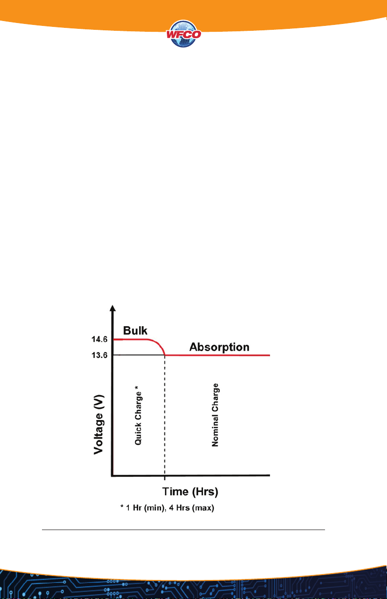
LEAD ACID & AGM THREE-STAGE SMART CHARGING
The three-stage “smart” charger continuously measures the battery voltage output and regulates
the amount of charge using three modes of operation: Absorption, Bulk, and Float.
3-STAGE CHARGING
WFCO converters of every style have become the favored brand for power conversion and
electric distribution in the RV industry. They provide RV owners wth an efcient and cost-effective
method to use an AC power source and provide power to DC components inside the RV, while
charging accessory batteries at the same time.
SMART ENGINEERING: THREE STAGE CHARGING IS BETTER
WFCO’s automatic three-stage converters handle every charging need for the RV while extending
the battery’s life. Well-maintained batteries should never need more than two-stage (Normal and
Trickle) charging. Our third stage (Bulk) is provided for the rare times a battery needs extra power
for charging.
RVs are frequently sold with at least one 12 VDC accessory battery installed. This battery is
normally a deep-cycle battery that could sustain a slower drain of power. RV owners nd this
useful when powering loads such as lights, radios, and refrigerators without being
connected to AC power or running the motorhome engine. As soon as the RV is connected to
AC power, the converter begins charging the battery as needed, while, at the same time, provid-
ing 12 VDC power to loads such as lights, radios, and refrigerators.
When the RV is connected to AC power, users frequently use the lights, refrigerators, fans, and
other electronics as they would in their home. RV users also expect the battery to be fully charged
when they want to disconnect from power and move the RV, or when they are dry camping and
turn off their generator.
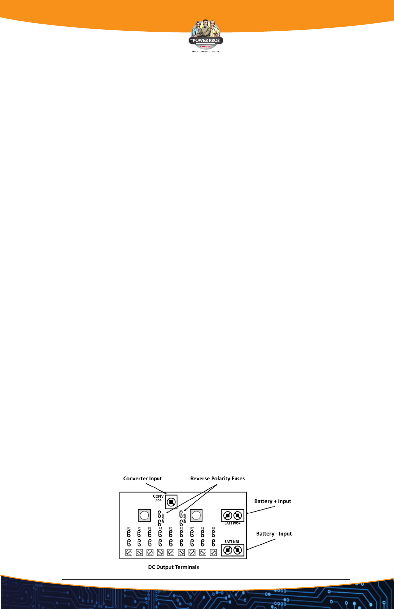
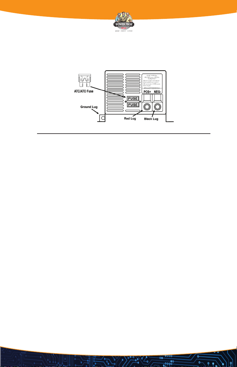
OPERATIONAL FEATURES