manuals.online logo
Brands
  1. Home
  2. •
  3. Brands
  4. •
  5. Wfly
  6. •
  7. Transmitter
  8. •
  9. Wfly ET08 User manual

Wfly ET08 User manual

Scan to add WFLY official Wechat
Enter "ET08 manual" to download the detailed specification!
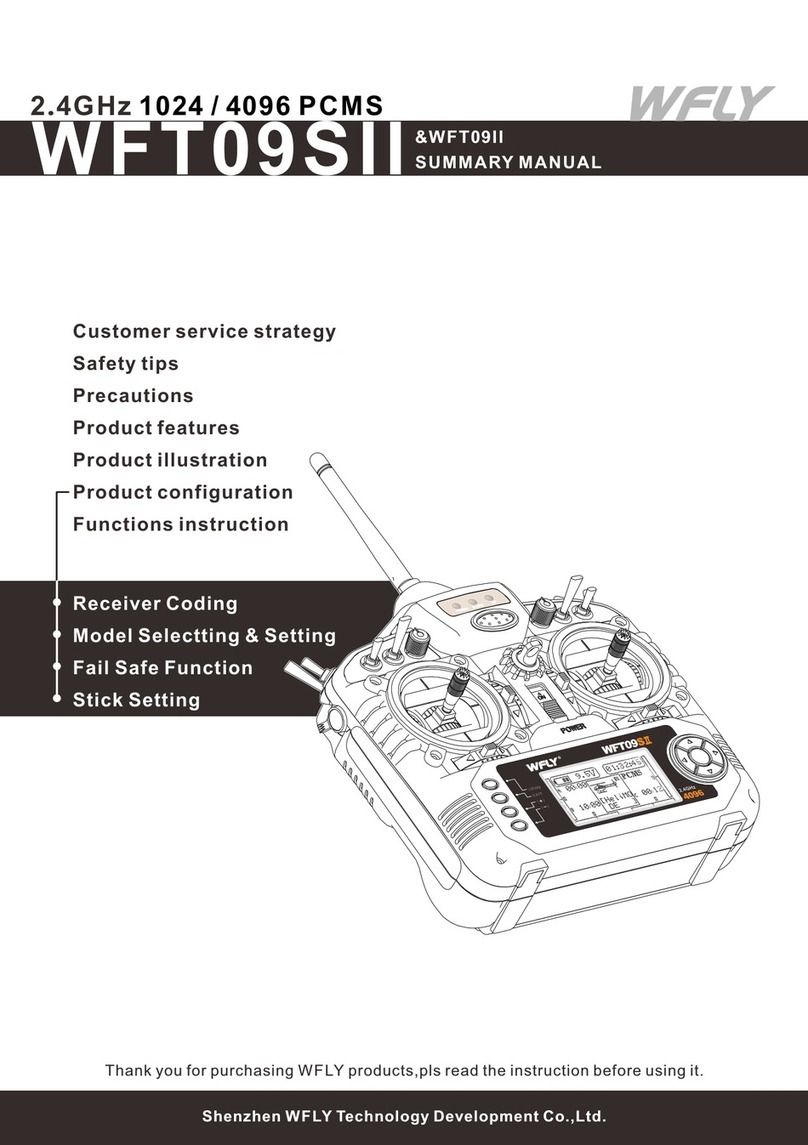
ET08 Summary Manual
WFLY
Shenzhen WFLY Technology Development Co.,Ltd No fly when user is in poor health condition such as fatigue and drunkenness.
No fly near high voltage wires, communication base stations, government secret zone
or public places where crowds gathered.
No fly in airports and other places where fly is forbidden.
Before flying, test the equipment, check whether the transceiver system and the
aircraft are normal;
When flying, make the interface of transmitter in the standby interface in case of the
parameters changed by mistake;
After flying, turn off the receiver primarily before the transmitter turn off to protect
people from rotary of engine or motor caused by fail-safe function
Beginners should pay particular attention to the following safety precautions! Please
read carefully!
The sequence of power on and off of transmitter and receiver!
No fly in bad weather day such as rain, strong wind or at night, etc.
Please take care of the product!
The electronic product should be dry, use alcohol and special cleaner to clean.
*Power off:
No under sunshine or in high temperature, wet or dusty place.
The screen is vulnerable, do not press hard or scrape with sharp things.
*Power on:
Firstly turn on the transmitter (ensuring the minimum position of throttle stick
),Secondly Turn on the receiver
Firstly turn off the receiver, Secondly turn off the transmitter.
Use guaranteed and special charger to charge the battery;
Preserve the battery with special case for safety.
Do not force the vulnerable antenna, or it may cause destroy.
ET08 is with LiFe 3.7V-6V. RF206S working voltage is 3.8V-6.5V.Charge with others
kinds of batteries would damage the transmitter.
Charge and attentions:
Upgrade: USB upgrade
Wireless copy: Model data
Type: RF206S
Transmitter
Channel: 8 channels
Current: 150mA
HFSS:64points,3.6ms
Display: 3.5 inches, 128x64 dot matrix screen
Applications: Helicopters/airplanes/muti-copters/robots/cars/boats
Relay Flight: Support
Resolution: Full channel 4096
Program: 5 program mix
Language: Chinese, English
Model: ET08
Voltage: 3.7V-6V (1S lithium battery)
Band: 2.4GHz(bidirectional)
Storage: 16 groups
180°/270° servo: Support
Receiver
Band: 2.4GHz
Frequency: FHSS 4096
W.BUS: Compatible S.BUS
Two-way transmission: Support
Fail-safe: Support
180/270° servo: Support
PWM: 6 channels
Receiver Port Setting: Support
Dimention: 36x20x12mm
PPM: Support
Voltage: 3.8V-6.5V
Current: 80mA
External Voltage Detection: DC 0~36V
Safety Items Technical Parameters
11-21.Timer 2
4-5-7-8.Trim monitor, display active
trimming status
19.Return data(Receiver voltage)
15.Receiver signal strength
23."Home interface2",“Confirm
Key”"Return Key" or"Home Key" switch
back to "Home Interface 1"
3.Return data(External battery)
1-20.Timer 1
6."Home2" key, click to enter Home
Interface 2
12.User name, click into user defined
name
9.Model name: Click to enter model
select interface
13.Transmitter battery voltage
18.Fly mode, current fly mode
14.Lock(Click EXIT/LOCK 2s to enter
lock status)
16.Student (S), Trainer(T), 8channel
simulator(8)mode status
22.Return data(External battery
voltage)
2.Return data(Receiver voltage)
10.Model type: Click to enter current
model type interface
17.Throttle hold ( ) and throttle cut
( )status
MAIN INTERFACE INTRODUCTION
LD/RD: Rotary Knob(User-defined)
T1-T4:Trim,(User-defined)
SA: 2 positions; alternate; Short lever
Power LED: Left, Red
Power Button: Click the power key for 3 seconds to Startup & Shutdown.
SC: 3 positions; alternate; Long lever
RF LED: Right, Blue
SD: 2 positions; alternate; Short lever
TRAINER:Trainer port
5-way button: Move the cursor button up and down or left and right,
middle button for confirmation(Long press to reset).
HOME/MON.: Home/Monitor key, slightly click home, press and hold
monitor.
EXIT/LOCK: Exit/Lock key, slightly click to exist, press and hold to
lock the screen.
SB: 3 positions; alternate; Long lever
Home2 23
20
21
18
19 22
Home1
56 7
8
9
10
11
12
13
14
15
1617
1
2
3
4
18
For after-sale service,
please visit WFLY official website at www.wflysz.com
PARTS NAME AND FUNCTION INTRODUCTION
EXIT/LOCK
Carry Handle
SB Switch Block
SA Switch Block
HOME/MON.
Trim 3
Trim 4
LD Rotary Knob
Display Screen
Power Button
Power LED
Stick
J3
J4
J2
J1
Stick
Trim 1
Trim 2
Antenna
RD Rotary Knob
SC Switch Block
SD Switch Block
RF LED
5-way Button
Hook
TRAINER USB upgrading port
3.There is no other WFLY 2.4 GHz systems linking nearby.
Setting method:
2.Linking cannot be operated when transmitter is in Simulator, Student mode (System
Setting→Trainer);
5.Connection and validation must be done after linking.
1.Charge the receiver , press and hold "SET" key for 3 second, the orange light flash.
Cautions:
When Linking, do not connect the power equipment or dismantle the propeller.
Caution!
4.When linking, press 'cancel' or return button to quit if necessary.
3.When successfully linking, the RF light of transmitter is on, the green light of
receiver is on (W.BUS mode), or the blue light in on (PPM mode),or the purple light is on
(PWM mode).
1.The distance between transmitter and receiver must be near (less than 1 meter).
2.For transmitter, press "start" button to link: [LINKAGE SETTING] → [LINK] →
press"start"
6.Only when the telemetry works during linking status, can the telemetry information
be obtained, and shutdown protection is enabled at the same time.
Validation: Connect the servo and operate the remote control,if the corresponding
servo has synchronous action output, the link is successful
Provides 4 operating modes, customized operating mode at the [FUNCTION]
additionally.
Custom operating mode: You need to modify the definition in [FUNCTION]. After the
modification, the [Stick mode] interface mode changes to "User-defined".
([FUNCTION] 1-4 channel stick settings)
Setting method: [SYSTEM SETTING] →[STICK MODE]
Changing the stick mode involves setting the contents of [function] in [GENERAL
MENU].
Note:
Select (1, 2, 3, 4) mode, there will be a safety prompt for each operation, select "Yes"
to save directly.
Save:
1.Low voltage warning
*Low voltage alarm of transmitter: when the power is lower than the self-defined
voltage, the buzzer will ring
*Warning interface pop-up prompt, press "CONTINUE" or put the throttle stick to the
lowest position, then continue to power on normally!
*When the throttle stick is not at the lowest position, the buzzer will alarm until the
throttle stick is at the lowest position.
*When low power is encountered during use, the buzzer will alarm, and the voltage
value at the upper right corner of the display screen (transmitter low voltage) or at the
lower left corner (receiver low voltage or external low voltage) will flash
When starting, the switch position is not in the default position, the interface will
appear (display the corresponding alarm switch), and all switches in the default position
will disappear.
2.Throttle stick position alarm when power on
4. Shutdown alarm interface
After the telemetry function is turned on, the transmitter will detect whether the
receiver communicates or not, and the communication will pop up a warning interface and
need to be confirmed before shutdown.
3.Switch position alarm
When trimming at the midpoint or endpoint, the buzzer will go off.
5.Linking
6.Warning of trim
Once finished link, the buzzer alarms once. When linking times out, the buzzer alarms
once and link status exits automatically.
Save:Switch the "model type", set the "wing type" and "tail type". Select the "OK"
button to save the data, the screen returns to the standby interface. The current (standby
interface) model type picture has changed to the modified model.
Setting method:[SYSTEM SETTING]→[MODEL TYPE]
*The selection of the "flywin" model is as follows:
[MODEL TYPE] - [PLANE] - [FLYWIN] - [NORMAL]
The parameter suggested
F/S, receiver outputs the set value after fail safe (preset action)
(Only for suggestion, other settings are based on actual situation)
Reduce the rate of body injury,UAV crash, lost or explosion when the aircraft lost
control.
Advice: Before each debugging or preparation flying, in order to avoid very dangerous
conditions such as falling when the throttle is fully open, the fail safe data should be set
before other operations.
2.For airplane/glider,throttle set to lowest or idle down, other channels set as smooth
or hovering, because airplane/glider can slip down without power
Set fail-safe data firstly before calibration or flight .
HOLD: Hold mode, the receiver outputs the F/S value after fail safe(hold action)
1.[LINKAGE SETTING ]→ [FAIL SAFE], to enter the F/S interface.
OFF: Shut down the current channel output (only for some special models or some
flight-control panel detection ports)
3.Set fail-safe value: F/S value can only be set under F/S mode, click numeric frame
for current channel value.
Attention:
The importance of Fail-safe:
2.Set mode:
For safety, you can refer to following suggestion or consult after-sales service.
Steps:
1.For helicopter, throttle set to lowest value, other channels set as smooth flight mode
3.For multicopter,please refer to FC(flight Control) manual.
LINK
STICK MODE
Interface And Buzzer Warning
Model Type
Transmitter LED Status
Receiver LED Status List
FAIL-SAFE
Working Mode Action
Work
Purple Never PWM normal work mode
Green Never W.BUS normal work mode
Blue Never PPM normal work mode
Red Never No signal
Red Slowly flash Low voltag e
Orange Slowly flash Link
LED Status
Power LED on Power on
Power LED off Power off
RF LED off Power off Student or Simulator mode
RF LED on Normal Linkage Trainer or Normal mode
RF LED flash Enter link status
、
、
Aileron 1
(channel 1)
Aileron 2
(channel 2)
Travel: Aileron 1, aileron 2
*Path: [GENERAL MENU] - [END POINT]
*Setting path:[GENERAL MENU] -
[SERVO REVERSE]
Reverse Setting:Aileron 1, aileron 2 (if the
steering angle is in the wrong direction, check
the steering gear connection is correct, then
proceed to the positive and negative settings)
Shut down and charg e
Power lig ht is on Charging
Power lig ht off Full charg e

Other Wfly Transmitter manuals

Wfly WFT09SII User manual

Wfly

Wfly WFT09SII User manual

Wfly RF206S User manual

Wfly

Wfly RF206S User manual

Wfly X4 User manual

Wfly

Wfly X4 User manual

Popular Transmitter manuals by other brands

Rf-t Help Alert quick reference

Rf-t

Rf-t Help Alert quick reference

AVPro Edge AC-CXWP-HDMO-T quick start guide

AVPro Edge

AVPro Edge AC-CXWP-HDMO-T quick start guide

AVProConnect AC-EX100TT-UHD-T user manual

AVProConnect

AVProConnect AC-EX100TT-UHD-T user manual

Dini Argeo DGT1P user manual

Dini Argeo

Dini Argeo DGT1P user manual

JUMO dTRANS T04 operating instructions

JUMO

JUMO dTRANS T04 operating instructions

Burkert SE58 L operating instructions

Burkert

Burkert SE58 L operating instructions

Ebyte E104-BT30-TB1 user manual

Ebyte

Ebyte E104-BT30-TB1 user manual

NIVELCO EasyTREK SP-500 Pro Installation and programming manual

NIVELCO

NIVELCO EasyTREK SP-500 Pro Installation and programming manual

Dwyer Instruments AVLV Series Specifications-installation and operating instructions

Dwyer Instruments

Dwyer Instruments AVLV Series Specifications-installation and operating instructions

Absolute Process Instruments Cecomp F16DR Series instructions

Absolute Process Instruments

Absolute Process Instruments Cecomp F16DR Series instructions

Steren MP3-053 user manual

Steren

Steren MP3-053 user manual

ACM TX-PLUS manual

ACM

ACM TX-PLUS manual

Duon System Co., Ltd AUTROL APT3700N Series Operation manual

Duon System Co., Ltd

Duon System Co., Ltd AUTROL APT3700N Series Operation manual

Shure AXIENT DIGITAL ADX2FD user guide

Shure

Shure AXIENT DIGITAL ADX2FD user guide

EBS WX2NB Installation and programming manual

EBS

EBS WX2NB Installation and programming manual

Emerson Rosemount CX1100 Reference manual

Emerson

Emerson Rosemount CX1100 Reference manual

FlowLine EchoSpan LU80-5101 quick start

FlowLine

FlowLine EchoSpan LU80-5101 quick start

Procare EF6237 quick start guide

Procare

Procare EF6237 quick start guide

manuals.online logo
manuals.online logoBrands
  • About & Mission
  • Contact us
  • Privacy Policy
  • Terms and Conditions

Copyright 2025 Manuals.Online. All Rights Reserved.