Wfly RF206S User manual

01
WFLY
Shenzhen WFLY Technology Development Co., Ltd
(ET Series)8-channel Digital Propor tional R/C System
ET08 INSTRUCTION MANUAL
WFLY Wechat

Thank you for using WFLY products!
● Please read this product manual carefully before using this product!
——Shenzhen WFLY Technology Development Co., Ltd
● Please use this product correctly!
The model is not a toy, for safety, please don't fly at crowded places!
02

CATALOGUE
03
A
06
06
07
08
08
B
09
09
10
11
11
C
12
13
13
14
15
16
17
18
D
19
20-21
Safety Precautions
Symbols Definition
Flying Precautions
Battery
Trainer Port
USB Port
Before Use
Product Features
Basic Configuration
Each Parts Name Of Transmitter
Switch Configuration and Model Types
The Travel of Antenna Direction Adjustment
Basic Operation
Home Interface Introduction
Indicator Light of Transmitter
Stick Adjustment
Left and Right Hand Mode Replacement Method
Receiver Instructions
Receiver and servo connection example:
-Airplane
-Helicopter
-Multicopter
Basic Setting Sequence of Models
-Airplane
-Helicopter

CATALOGUE
04
E
22
23
24
25
26
27
28
29
30
31
32
33
34
F
35
36
37
38
39
40
41
42
43
44
G
45
46
47
48
49
50
51
52
53
54
55
56
System Setting
Model Select
Model Type
Trainer
Display
User Name
Low Battery
Sound
Language
Stick Mode
Calibration
Data Reset
Information
Screen Lock Set
Linkage Setting
Link
Telemetry
PPM/W.BUS
Receiver Output
Fail Safe
Relay Flight
Servo Frequency
BUS Servo Setting
180/270° Servo
Range Check
General Menu
Monitor
Function
Servo Reverse
Dual Rate
End Point
Timer
Trim Setting
Sub-Trim
Channel Delay
Program Mixes
Flight Mode
Double Engine

CATALOGUE
05
H
57
58
59
60
61
62
63
64
I
65
66
67
68
69
70
71
72
73
74
75
76
J
77
78
79
80
81
82
Model Menu\Helicopter
Condition
Throttle Curve
Pitch Curve
Throttle Hold
Throttle Cut
Gyro
Governor
Swash
Model Menu\Airplane
Condition
AIL Differential
Throttle Curve
Throttle Hold
Throttle Cut
Gyro
Airbrake
ELE to Camber
Winglet
Elevator
V-Tail
Flywin
Model Menu\Multicopter
Condition
Throttle Curve
Throttle Hold
Throttle Cut
Stick Alarm
Gyro

Safety Precautions
Flying Precautions
Symbols Definition
WARNING
DANGER
NOTICE
Prohibitions Mandatory
Disclaimer & Warning
User should be responsible for any consequences caused by using the product. WFLY shall not be liable
for any directly or indirectly damage, injury and any legal liability, User shall comply with all guidelines
including but not limited to this document.
Please follow the local laws and regulations for regular flight activities. Do not use this product to carry
out personal safety, property safety or other bad flight behaviors.
To ensure the safety of yourself and others, please observe the following precautions:
Beginners should pay particular attention to the following safety precautions! Please read carefully!
No fly in bad weather day such as rain, strong wind or at night, etc.
Be careful when flying near electric wires, high-rise buildings or communication facilities, as there may
be radio interference around.
No fly in airports and other places where fly is forbidden.
Charge the batteries! Check transmitter and receiver battery level and always recharge the batteries
before each flying session. A low battery will soon die potentially, causing loss of control and a crash. When
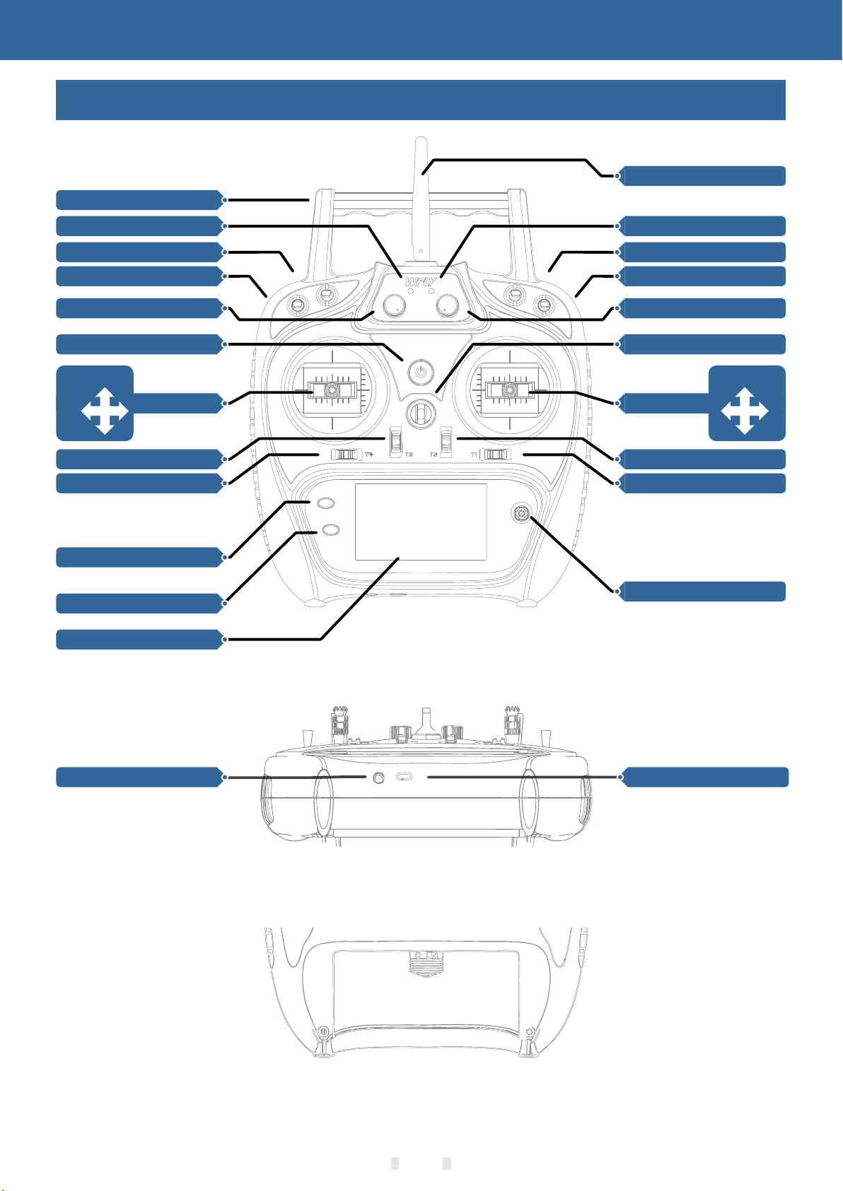
you begin your flying session, reset your ET08 built-in timer, and during the session, reset your ET08 built-
in timer, and during the session pay attention to the duration of usage.
Before flying, inspect the aircraft carefully, inspect whether the aircraft and transceiver system it's
normal. When flying, make the transmitter display to the initial interface, in case of mistaken parameter
change. After flight, turn off the receiver power before turn off the transmitter power, in case of any injury
caused by fail safe works.
Firstly turn off the receiver, Secondly turn off the transmitter.
More debugging, more testing, less loss, less damage!
Power on:
Transmitter and receiver low voltage may cause fail-safe danger!
Power off:
Note: The transmitter will display the warning interface, please pay attention to the transmitter
prompt! Improperly operation may cause accident injury to user.
No fly near high voltage wires, communication base stations, government secret zone or public places
where crowds gathered.
Firstly turn on the transmitter (ensuring the minimum throttle position), Secondly Turn on the receiver.
No fly when user is in poor health condition such as fatigue and drunkenness.
Power on and off sequency of transmitter and receiver!
Mandatory
Mandatory
06
Pay special attention to the safety information of the following symbols!
If without a proper operation,it may cause dangerous accident or seriously injury or
may even cause death.
If without a proper operation,it may cause dangerous accident or seriously injury or
may even cause death,and it may cause slight hurt or probability cause bodily injure!
If without a proper operation,it may cause less possibility to serious hurt,but it may
cause hurt or bodily injure.
WARNING
DANGER
NOTICE

Safety Precautions
Battery
3.Always provide adequate ventilation around LiFe batteries during charge, discharge, while in use, and
during storage.
4.Do not leave a LiFe battery unattended at any time while being charged or discharged.
Lithium polymer battery(Short for LiFe battery),please use the WFLY special charger only.It is important
to understand the operating characteristics of Li-Fe batteries.
1.Do not attempt to disassemble LiFe packs or cells.
2.Do not allow LiFe cells to come in contact with moisture or water at any time.
Long term storage (more than 3 months),storage temperature≤45°C general storage voltage 3.7-3.9v.
Failure to follow the proceeding precautions can quickly result in severe, permanent damage to the
batteries and possibly result in a fire!
12.Do not store batteries near an open flame or heater
13.Do not discharge LiFe batteries at currents which exceed the discharge current rating of the battery.
6.Always charge LiFe batteries in a fireproof location. Do not charge or discharge LiFe batteries on
carpet, a cluttered workbench, near paper, plastic, vinyl, leather or wood, or inside an R/C model or full-
sized automobile! Monitor the charge area with a smoke or fire alarm.
14.Always store LiFe cells/packs in a secure location away from children.
11.Do not use a LiFe battery if you suspect physical damage has occurred to the pack. Carefully inspect
the battery for even the smallest of dents, cracks, splits, punctures or damage to the wiring and
connectors.DO NOT allow the battery’s internal electrolyte to get into eyes or on skin—wash.affected areas
immediately if they come in contact with the electrolyte. If in doubt, place the battery in a fire-proof location
for at least 30 minutes.
7.Do not charge LiFe batteries at currents greater than the “1C” rating of the battery (“C” equals the rated
capacity of the battery).
10.It is normal for the batteries to become warm during charging, but if the charger or battery becomes
excessively hot disconnect the battery from the charger immediately!! Always inspect a battery which has
previously overheated for potential damage, and do not re-use if you suspect it has been damaged in any
way.
ET08 adopts the power supply mode of lithium battery, and the working voltage adapts to the range of
3.7-6V. Using a power supply that exceeds the operating voltage stroke may burn the machine!
The USB interface of ET08 can be used to charge the common mobile phone charger (5V)!
8.Do not allow LiFe cells to overheat at any time! Cells which reach greater than 140 degrees Fahrenheit
(60°C) should be placed in a fireproof location.
Receiver (RF206S):
Transmitter (ET08):
The receiver's operating voltage adapts to the range 3.8V-6.5V, with anti-reverse protection slot (power
input pole, positive and negative reverse protection). With a power supply that exceeds the operating
voltage stroke, the receiver will burn out!
5.Do not attempt to charge LiFe batteries with a charger that is NOT designed for LiFe batteries, as
permanent damage to the battery and charger could result.
9.LiFe cells will not charge fully when too cold or show full charge.
07
NOTICE
NOTICE
DANGER

USB Port
Warning: This port is only used as upgrading
data transmission, it is forbidden to insert the
power supply (high voltage) terminal to the USB
port to avoid damage for the transmitter
ET08 adopt standard USB port for upgrading
function!
Transmitter USB port:
Mandatory
Safety Precautions
Trainer Port
The trainer port is with 3.5mm audio port output
mode. This suite is without the trainer data line. If
you want to use the trainer function, you need to
purchase the trainer data line separately!
Transmitter trainer port:
Warning: This port is only used for trainer data
transmission. It is forbidden to insert the power
supply (high voltage) terminal to the port to avoid
damage for the transmitter.
Mandatory
Trainer/Simulator port
USB port
08

Before Use
Transmitter
Model: ET08
Channel: 8 channels
Voltage: 3.7V-6V (1S lithium battery)
Current: 150mA
Applications: helicopters/airplanes/multicopters/robots/cars/ boats
Resolution: full channel 4096
Band: 2.4GHz(bidirectional)
HFSS:64points,3.6ms
Storage: 8 groups
Program: 5 program mix
Language: Chinese, English
Upgrade: USB upgrade
Display: 3.5 inches, 128x64 dot matrix screen
Relay flight: support
180/270° servo: support
Wireless copy: model data
Receiver
Type: RF206S
Band: 2.4GHz
Voltage: 3.8V-6.5V
Current: 80mA
Applications: helicopters/airplanes/multicopters/robots/cars/ boats
Frequency: FHSS 4096
PWM: 6 channels
PPM: support
W.BUS: compatible S.BUS
Two-way transmission: support
Fail-safe: support
180/270° servo: support
Receiver port setting: support
External voltage detection: DC 0~36V
Dimention: 36x20x12mm
Product Features
Basic Configuration
Transmitter Receiver Summary Manual
09
RF206S receiver x1(include external power detection line x1)
ET08 transmitter x1
Summary manual x1

EXIT/LOCK
Carry handle
SB Switch Block
SA Switch Block
HOME/MON.
Trim3
Trim4
LD Rotary Knob
Display Screen
Power Key
Power LED
Stick
J3
J4
Trim1
Trim2
Antenna.
RD Rotary Knob
SC Switch Block
SD Switch Block
RF LED
5-way Button
Hook
Stick
J2
J1
Before Use
Each Parts Name Of Transmitter
TRAINER
Battery cover
USB Upgrade Port
10

Switch configuration and model types
The Travel Of Antenna Direction Adjustment
SA: Short lever 2 positions (user-defined)
Power LED: Left, power indicator light, red
RF LED: Right, RF indicator light, blue.
POWER: Click and hold for 3 seconds to open/shut down;
SB: Long lever 3 positions (user-defined)
SD: Short lever 2 positions (user-defined)
SC: Long lever 3 positions (user-defined)
LD/RD: Rotary Knob(User-defined)
TRAINER: Trainer port
5-way button: Move the cursor button up and down or left and right, middle button for confirmation(Long
press to reset).
T1-T4:Trim,(User-defined)
EXIT/LOCK: Exit/Lock key, slightly click to exist, press and hold to lock the screen.
HOME/MON.: Home/Monitor key, slightly click home, press and hold monitor.
Mandatory
Before Use
Transmitter faces upside
As the picture shows
Receiver faces upside
As the picture shows
Strong
signal acquisition
Weak
signal acquisition
11
Avoid metal objects covering the handle position when in use.
The following is the "antenna position indication image" and "signal strength and position
relationship diagram":
90°

Basic Operation
Home Interface Introduction
Home Interface 1
1
2
3
4
56 7
8
9
10
11
12
13
14
15
16
23
Home Interface 2
20
21
22
18
19
17
18
12
Introduction and operation
1-20.Timer 1
2.Return data(Receiver voltage)
3.Return data(External battery)
4-5-7-8.Trim monitor, display active trimming status
6."Home2" key, click to enter Home Interface 2
9.Model name: Click to enter model select interface
10.Model type: Click to enter current model type interface
11-21.Timer 2
12.User name, click into user defined name
13.Transmitter battery voltage
14.Lock(Click EXIT/LOCK 2s to enter lock status)
15.Receiver signal strength
16.Student (S), Trainer(T), 8channel simulator(8)mode status
17.Throttle hold ( ) and throttle cut ( )status
18.Fly mode, current fly mode
19.Return data(Receiver voltage)
22.Return data(External battery voltage)
23."Home interface2",“Confirm Key”"Return Key" or"Home Key" switch back to "Home Interface 1"

Basic Operation
Indicator Light of Transmitter
Stick Adjustment
Stick head height adjustment:
2. Then twist the lower head to adjust the height
3. Twist the upper head clockwise to lock it
1. Loosen the upper section head counterclockwise
LED
Status
Power LED on
Power on
Power LED off
Power off
RF LED off
Power off , Student or Simulator mode
RF LED on
Normal Linkage, Trainer or Normal mode
RF LED flash
Enter link status
Power LED
Red
RF LED
Blue
13

Basic Operation
Left and right stick mode replacement method
It is not recommended to replace the left and right sticks by yourself, otherwise the transmitter may be
damaged.
1 Loosen the bearing housing screws (the screws do not need to be fully retracted), then remove the
spring, bracket 7 and bracket 5 and tighten the screws; then remove the removed spring, bracket 7 and
bracket 5 in another assembly corresponding position (remove the bearing housing screw before
assembly),The tightness of the stick can be changed by adjusting the height of screw 3.
Required tools: 3 mm cross screwdriver, 1.5 mm hex driver
Firstly open the transmitter housing and then follow the instructions shown below:
2 Remove the screw of the throttle reed, the throttle reed and the throttle sleeve, and install them in the
corresponding position of the other assembly. According to your own habits, select the type of throttle
sliding (toothed and smooth) and adjust the screw (screw 1 or The height of the screw 2) makes the
damping of the throttle conform to your own habits.
Screw 2
Throttle reed Throttle sleeve
After the throttle structure is modified, turn on the machine, enter [system setting] → [stick mode], select
the corresponding operation mode, and then adjust the stick after replacing the left and right modes! If you
need components such as bracket 5 (such as the parts needed for assembling double circuit structure!), you
can e-mail to WFLY overseas seller to order the spare parts at sales@wflysz.com.
Bracket 5 Bracket 7
Spring
Throttle sleeve
Screw 1
①
Screw 3
Screw 3
Bearing
housing screw
14

Basic Operation
Receiver Instructions
Receiver LED STATUS LIST
PPM/W.BUS/PWM port modes select: Enter the
interface [LINKAGE SETTING] - [RECEIVER
OUTPUT], switch the working status of the last port
of the receiver (default 6 channels), and return to
the previous interface to save the settings.
Link: Charge the receiver then press and hold
'SET' button for 3 seconds,wait for the link
instruction after the orange light slowly
flashes(LINKAGE SETTING)→(LINK).
Mode
LED
Action
Status
Work
Purple
Never
PWM normal work mode
Green
Never
W.BUS normal work
Blue
Never
PPM normal work mode
Red
Never
No signal
Red
Slowly flash
Low voltage
Orange
Slowly flash
Linking
1.If there is a metal conductor around the receiver antenna,the signal performance would be affected.
In this case, the antenna should be bypassed by the conductor, placed on both sides of the fuselage, and
it is better to make the antenna leak outside the model casing ! In this way, good signal reception can be
maintained regardless of the flight attitude.
2. When the antenna is installed. The unshielded end of the antenna should be as far away as possible
from the conductor materials such as metal and carbon fiber. The antenna cable avoids bending at large
angles. And the end core should be as straight as possible.
3. If the model body is covered with a conductive material such as carbon fiber or metal, the antenna
portion must be extended beyond the body. At the same time, do not stick too close to the conductive body
after the antenna is extended. In addition, the antenna should also be kept away from the fuel tank.
The receiver has an external battery detection interface, which can be used to view voltage information
such as ESC, battery, etc., and the transmitter can separately set alarm voltages for the receiver voltage
and external voltage. Pay attention to the positive and negative polarity when using the detection wire!
Mandatory
90°
Keep the
antenna
straight
Signal
Positive
Negative
W.BUS/PPM/PWM
External voltage detection
port polarity signs
Ext.voltage
The resistance is connected
to the negative pole
The red is connected to the
positive pole
1Ω
15
Notice: pay attention to the positive and negative
polarity when connecting the power supply. Do not
use the power supply that exceeds the working
voltage of the receiver. Otherwise, the receiver will
be damaged!
Receiver connection and installation
The working voltage of the receiver is 3.8-6.5V.
Each port can be used as the power input terminal.
The RF206S is the newest series of high
performance receiver with 6 PWM channels, the last
channel port is PWM/PPM/W.BUS channel (User
defined).
In order to obtain optimal signal retrieval
performance, the two antennas are preferably
processed 90° to each other when installed, as
shown in the right diagram.

Basic Operation
Receiver and servo connection example - Airplane
The figure below shows an example of airplane connection. Please use the actual wing type and tail type
for servo connection.
Servo connection position (Airplane,refer to stick mode "Mode 1")
The table below shows examples of the servo connection positions for the different wing types and
tail types(system default settings)
16
CH1/Aileron
CH2/Elevator
CH3/Throttle
CH4/Rudder
CH5/Gear
CH6/Aux1
Type Wing Delta wing Tail CH1 CH2 CH3 CH4 CH5 CH6 CH7 CH8
Channel AIL ELE THR RUD Gear AUX1 AUX2 AUX3
Control J1 J3 J2 J4 SD -- -- --
Trim T1 T3 T2 T4 -- -- -- --
Channel AIL ELE THR RUD Gear AUX1 AUX2 AUX3
Control J1 J3 J2 J4 SD -- -- --
Trim T1 T3 T2 T4 -- -- -- --
Channel AIL ELE THR RUD Gear 升降2 AUX2 AUX3
Control J1 J3 J2 J4 SD -- -- --
Trim T1 T3 T2 T4 -- -- -- --
Channel AIL ELE THR RUD Gear AIL2 AUX2 AUX3
Control J1 J3 J2 J4 SD -- -- --
Trim T1 T3 T2 T4 -- -- -- --
Channel AIL ELE THR RUD Gear AIL2 AUX2 AUX3
Control J1 J3 J2 J4 SD -- -- --
Trim T1 T3 T2 T4 -- -- -- --
Channel AIL ELE THR RUD ELE2 AIL2 AUX2 AUX3
Control J1 J3 J2 J4 -- -- --
Trim T1 T3 T2 T4 -- -- -- --
Channel AIL AIL2 THR RUD Gear ELE AUX2 AUX3
Control J1 -- J2 J4 SD J3 -- --
Trim T1 -- T2 T4 -- T3 -- --
Channel AIL AIL2 THR RUD RUD2 ELE AUX2 AUX3
Control J1 -- J2 J4 -- J3 -- --
Trim T1 -- T2 T4 -- T3 -- --
Airplane
1 AIL Normal
2 AIL Normal
1 AIL V-Tail
1 AIL Ailevator
2 AIL V-Tail
2 AIL Ailevator
2AIL Normal
2AIL Winglet

Basic Operation
Receiver and servo connection example - Helicopter
The figure below shows an example of helicopter connection. Please use the swash type that is actually
used for the servo connection.
Swash Types
H-1
Normal
HR3(120°)
PIT AIL
ELE
17
Servo connection position (Helicopter,refer to stick mode "mode 1")
The table below shows examples of the servo connection positions for different swashes.
GRO
CH1/Aileron
CH2/Elevator
CH3/Throttle
CH4/Rudder
CH5/Gyro
CH6/Pitch
Type Swash CH1 CH2 CH3 CH4 CH5 CH6 CH7 CH8
Channel AIL ELE THR RUD Gyro PIT AUX2 AUX3
Control J1 J3 J2 J4 -- J2 -- --
Trim T1 T3 T2 T4 -- -- -- --
Channel AIL ELE THR RUD Gyro PIT AUX2 AUX3
Control J1 J3 J2 J4 -- J2 -- --
Trim
T1 T3 T2 T4 -- -- -- --
Helicopter
H-1
HR3

Receiver and servo connection example - Multicopter
This figure is for illustrative purposes only. Link amplification also changes depending on the multicopter
collective and the flight controller. Please connect according to the instruction manual of the multicopter kit
to be used.
Servo connection position (Multicopter,refer to stick mode"Mode 1")
The figure below shows the four-rotor multicopter. Please refer to the model manual for specific
applications. Motor,electronic speed controller, flight controller, battery, etc. are sold separately.
Use 5CH-6CH when using accessories such
as camera shutters. Use a W.BUS interface or
dual receiver when the channel is insufficient.
Battery
Motor、ESC
(buy seperately)
CH1 Aileron
CH2 Elevator
CH3 Throttle
CH4 Rudder
CH5
Multicopter
flight controller
18
Basic Operation
Type CH1 CH2 CH3 CH4 CH5 CH6 CH7 CH8
Channel AIL ELE THR RUD Flight mode AUX1 AUX2 AUX3
Control J1 J2 J3 J4 -- -- -- --
Trim T1 T2 T3 T4 -- -- -- --
Multicopter

Basic Operation
Basic setting sequence of airplane
1. Call of the model
The Rename feature makes it easy to make a
selection call to a model whose name has already
been set.
The name of the model currently in use is
displayed on the home page. Before flying and
changing the parameter settings, be sure to
determine if the correct model is selected.
The ET08 transmitter has 16 built-in models from
the factory, and you can use the [MODEL SELECT]
under [SYSTEM SETTING] to call up the existing
model.
When a new model is added, please select
[MODEL TYPE] under [SYSTEM SETTING]
according to the model used. If a new receiver is
used, the receiver's link operation is also
required[LINKAGE SETTING]-[LINK].
2. Model type selection
Use the [MODEL TYPE] function under [SYSTEM
SETTING] to select the model type, wing type, and
tail type that match the model airplane.
For example, the left and right azimuth servos
can be selected from the main wing type by
selecting "2 ailerons" and adjusting the two servos
in [SUB-TRIM] and [END POINT] respectively.
● If the direction of the actual connection is
opposite to the direction you want, you can use
[SERVO REVERSE] under [GENERAL MENU] to
adjust the direction.
Install the ailerons, elevators, throttles, rudders,
etc. as required by the model aircraft product
specification. For the connection method, refer to
the "Receiver and Servo Connection Example -
Airplane" (P16).
[AIR BRAKE] function is used when landing, etc.,
when the sliding angle is large but the speed is no
need to be increased. This function can only be
used on models with [SYSTEM SETTING] - [MODEL
TYPE] and "2 Ailerons" on the wing.
7. Flight conditions
After the flight condition setting is completed, the
switch needs to be operated, and the condition
name displayed on the interface is confirmed.
*Normally, the left and right ailerons are
simultaneously set to the upward movement, and
the pitch of the nose can be corrected by the
elevator mixing when the function is started.
● Use the [END POINT] under [GENERAL MENU]
to adjust the end point and rotation angle of each
rudder surface, and use the [SUB-TRIM] function
and the [END POINT] function to make fine
adjustments. In order to protect the connecting rod,
the stroke limit position can be set in the [END
POINT] function item. [END POINT] function item
can adjust the up and down or left and right
movement amount of each rudder surface And limit.
Please use the [THROTTLE CUT] function option
under [MODEL MENU] to set. After the flame out
function is activated and the corresponding switch
is selected, the throttle position will be adjusted
until the carburetor is fully closed. For safety
reasons, the activation position of the throttle lever
position corresponding to the throttle stop function
can be set separately.
4. Throttle Cut Setting (Airplane)
● Install the throttle section to ensure that the
carburetor/electronic governor can be fully open or
fully closed.
[DUAL RATE] function is to match the feeling of
control and adjust the rudder angle, which makes
the control more convenient. The basic operating
range of the steering gear is set in the [END POINT]
function under [GENERAL MENU], and the steering
feel is adjusted by the [DUAL RATE] ratio function of
the [GENERAL MENU]. In addition, after setting the
rudder angle ratio, it can also be switched by the
switch or flight condition, and the flight action can be
used to call up the set rudder angle.
* When the [THROTTLE CUT] function is
activated, the engine flame out position will be fixed.
If the throttle cut switch is not required, use the [
IDLE DOWN] setting function below.
The factory default setting assigns only one flight
condition per model. Only one flight condition can
support basic flight without barriers, but if you are in
a competitive situation such as a game, you need
more detailed settings. Through the [CONDITION]
function in [MODEL MENU], you can select the
required flight conditions more effectively. It can
also be set for the switch of the condition switch and
the name of the condition.
Note: ET08 transmitters have different channel
assignments depending on the model type, so
please pay special attention (in the [FUNCTION]
option under [GENERAL MENU], you can check the
allocation of each channel).
The [THROTTLE CUT] function allows us to turn
off the engine by only one switch without affecting
the throttle trim position (after idle adjustment).
6.Air brake
3. The fuselage control part connect
5.Dual Rate Setting
19

Basic Operation
Basic setting sequence of the helicopter
There are 3 conditions that have been set.
● Idle
*This switch is not set in the default settings
If you have already set up a model, use the
[MODEL TYPE] selection interface to select the
helicopter in [SYSTEM SETTING], and then select
the helicopter "TYPE"and "SWASH TYPE"
according to the model.
2. Model type and swash plate type selection
3. Flight conditions setting
1. Model addition and invocation
The default setting contains the common mode
(default naming) conditions.
Please refer to the first part of the previous
section "Basic Operation - Basic Settings of
Airplane and Glider”
● Normal
● Hold
● Idle: usually used when stall turn, somersault
and other Idles.
The priority of these operation conditions is
3,Normal
Examples of common flight conditions settings:
4. Body control connecting rod installation
● Hold: usually used in the spin state
● Normal: (for default settings, switch off)
usually used when starting or hovering.
2,Idle
1,Throttle Hold
Install the throttle, tail rotor, aileron, elevator,
pitch, etc. as required by the model helicopter
product specification. The connection method can
be referred to the "Receiver and Servo Link
* In the [FUNCTION] option under [GENERAL
MENU], you can check the allocation of each
channel.
● If the direction of the actual connection is
opposite to the direction you want, you can use
[SERVO REVERSE] under [GENERAL MENU] to
adjust the direction. In addition to the H-1 mode,
you can also change the direction using the
[SWASH] function
● Set the direction of the gyroscope (this is the
"Gyro" function)
● The throttle section should be installed to
ensure that the carburetor can be completely closed
when trim is fully closed.
● Use the [END POINT] under [GENERAL
MENU] to adjust the ravel amount and rotation
angle of each rudder surface, and use the [SUB-
TRIM] function and the [END POINT] function to
make fine adjustments. In order to protect the
connecting rod, the travel limit position can be set in
the [END POINT] function item.
The [END POINT] function item can adjust the up
and down or left and right movement amount and
limit of each rudder surface.
The swash calibration (except H-1 mode) can
calibrate the swash motion by the correction mixing
control of the [swash] function. This function is
required when the pitch, aileron, and elevator
operations cause the swash to deviate from the
correct elbow.
Example - Helicopter" (P17) section.
The pitch curve of the idle is usually used for
flying through the air, and is generally set to-7°~+9°.
In the throttle lock and spin drop conditions, the
pitch should be set to the maximum in both the
●Pitch curve (Idle)
Use the flight condition selection switch to bring
up the throttle curve for each flight condition.
* Stable hovering is also related to throttle curve
setting. It is easier to achieve stable hover by using
throttle curve adjustment and pitch curve
adjustment.
● Throttle curve (Normal)
The pitch curve can be called up under each
condition using the flight condition selection switch.
● Throttle curve (Hold)
<Setting example>
Throttle curve setting example is as follows:
In the pitch curve, the hover pitch is usually set to
approximately +5°~+6°. Under normal
circumstances, the throttle stick is hovered at 50%
position as the standard.
The normal curve uses a normal line type, and the
basic pitch curve is set near the hover point (50% of
the stick). This curve is usually adjusted with the
pitch to ensure that the engine speed is uniform and
the up/down action is easy to handle.
This setting is to maintain stick rotate when the
throttle lever is in the low position.
Bring up [THROTTLE CURVE] or [PITCH
CURVE] from the [MODEL MENU] and set the curve
for various flight conditions.
In addition, the pitch of the link at the low point
and the high point can also be calibrated, which is
used to ensure the horizontal state of the swash in
the full stroke range.
● Throttle curve (Idle)
Note: throttle hold curve is used for spin landing.
Make sure the ratio of the lowest position (0%) of
the throttle control lever is 0% (this is the initial
setting).
5. Throttle Curve, Pitch Curve setting
Examples of pitch curve settings are as follows:
●Pitch curve (Normal)
●Pitch curve (HOLD)
20
This manual suits for next models
1
Table of contents
Other Wfly Transmitter manuals
Popular Transmitter manuals by other brands

Evikon
Evikon PluraSens E2670-PID user manual

Woxcon
Woxcon TPHD463 user manual

Pfeiffer Vacuum
Pfeiffer Vacuum RPT 100 operating instructions

Superior Broadcast
Superior Broadcast SBFM1000SS user manual

Inovonics
Inovonics EE1216 Installation instructions manual

Armstrong
Armstrong AMC-210 Series instructions