Whale Heat Air SL5511Ux Administrator Guide

Munster Simms Engineering Ltd., 2 Enterprise Road, Bangor, Co Down, BT19 7TA, U.K. –Northern Ireland
tel.: +44 (0)2891 270 531 fax.: +44 (0)2891 466 421 info@whalepumps.com www.whalepumps.com
Page |1 of 34
Heat Air Room Heater
This data is confidential to Brunswick
Whale Heat Air Room Heater
– How To Guide
This document is solely for guidance purposes and must only be used for reference by Whale®
Approved Service Engineers when servicing or repairing Whale® Heat Air Room Heaters.
Note: Images shown are for illustration purposes only.

Munster Simms Engineering Ltd., 2 Enterprise Road, Bangor, Co Down, BT19 7TA, U.K. –Northern Ireland
tel.: +44 (0)2891 270 531 fax.: +44 (0)2891 466 421 info@whalepumps.com www.whalepumps.com
Page |2 of 34
Heat Air Room Heater
This data is confidential to Brunswick
Contents
Contents..................................................................................................................................................2
1.0 General..............................................................................................................................................3
1.1 Application....................................................................................................................................3
1.2 Warnings ................................................................................................................................3
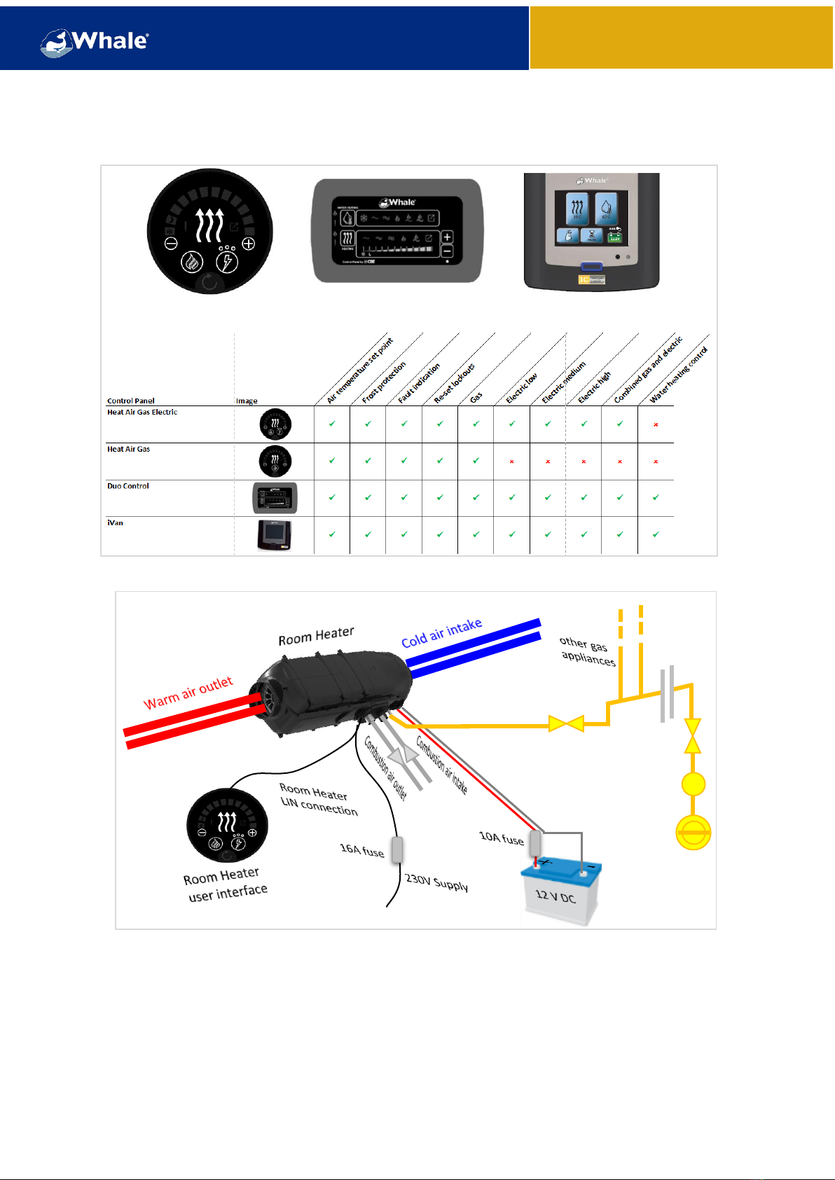
2.1 Product Description ......................................................................................................................5
2.2 Product Operation ........................................................................................................................5
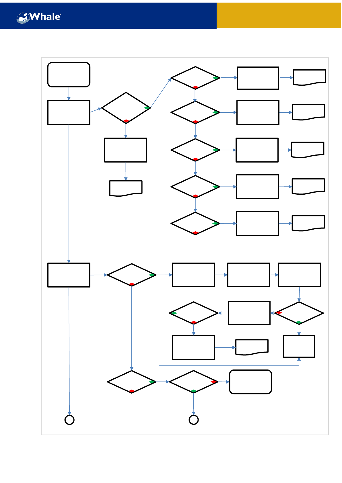
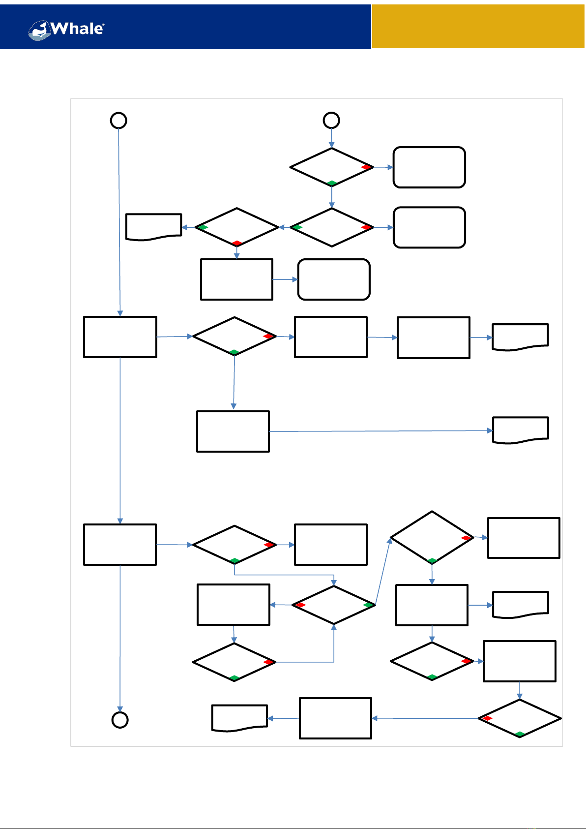
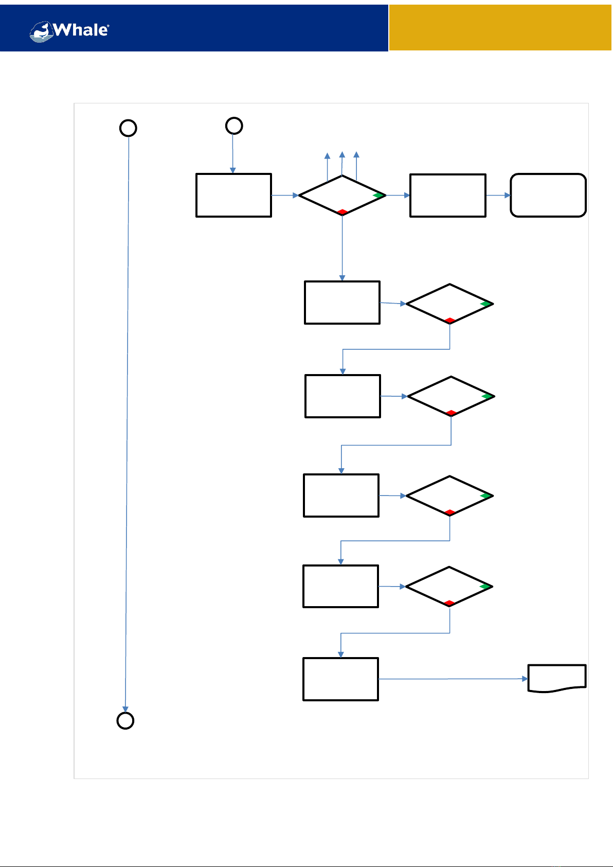
3.0 Fault Trees.........................................................................................................................................6
4.0 Troubleshooting..............................................................................................................................11
4.1 Lock outs/Fault codes .................................................................................................................11
4.1.1 Clear lockout procedure Heat and Duo Control Panel.........................................................11
4.1.1.1 –1 Bar: No flame detected...............................................................................................11
4.1.1.2 –2 Bars: Overheat.............................................................................................................12
4.1.1.3 –3 Bars: Low/High supply voltage....................................................................................12
4.1.1.4 –4 Bars: Combustion air fault...........................................................................................13
4.1.1.5 –5 Bars: Room Heater issues............................................................................................13
4.1.1.6 –All Bars: Multiple faults..................................................................................................13
4.1.2 Clear lockout procedure iVan Control Panel........................................................................14
4.2 Whale returns procedure............................................................................................................15
4.3 Initial steps required before replacing internal parts.................................................................17
4.4 Replacement of Blown Air Fan - AK1834 ....................................................................................17
4.5 Replacement of Gas Control PCB –AK1845, AK1846, AK1847...................................................18
4.6 Replacement of Electric Control PCB –AK1849..........................................................................19
4.7 Gas Component Replacement ....................................................................................................20
4.7.1 Replacement of Solenoid Coils –AK1842, AK1843, AK1844....................................................20
4.7.2 Replacement of Motor Units ...................................................................................................21
4.7.3 Replacement of Burner Assembly 4.0KW –AK1839/ Electrode AK1841.................................22
4.7.4 Replacement of Gas Heat Exchanger –AK1840.......................................................................23
4.8 Gas Overheat (O/H) Thermostat check and replacement - AK1854...........................................23
4.9 Temperature Sensor Gas–AK1852, Gas & Electric AK1853 check and replacement.................24
4.10 Assessment and replacement of Electric Element AK1850 ......................................................25
5.0 Spare parts......................................................................................................................................26
6.0 Contact details ................................................................................................................................29

Munster Simms Engineering Ltd., 2 Enterprise Road, Bangor, Co Down, BT19 7TA, U.K. –Northern Ireland
tel.: +44 (0)2891 270 531 fax.: +44 (0)2891 466 421 info@whalepumps.com www.whalepumps.com
Page |3 of 34
Heat Air Room Heater
This data is confidential to Brunswick
1.0 General
For over 60 years Whale® has led the way in the design and manufacture of freshwater and waste
systems including: plumbing, taps, showers and pumps for low voltage applications. Now providing
water and Room heating systems for recreational vehicles, the company and its products have built a
reputation for quality, reliability and innovation backed up by excellent customer service.
For information on our full product range visit: www.whalepumps.com
1.1 Application
These components have been designed for use only with Whale® Heat Air Room Heaters listed as
compatible. The Whale® Heat Air Room Heaters these instructions are applicable to are:
Figure 1 –Product range covered in this How to Guide
Heat Air part number
Description
SL5511Ux
Air 4KW Gas Uf Lin
SL6511Ux
Air 5KW Gas Uf Lin
SL5512Ux
Air 5KW Gas Elec Uf Lin
SL7512Ux
Air 6KW Gas Elec Uf Lin
SL5501Ox
Air 4KW Gas Ob Lin
SL6501Ox
Air 5KW Gas Ob Lin
SL5502Ox
Air 5KW Gas Elec Ob Lin
SL7502Ox
Air 6KW Gas Elec Ob Lin
- x denotes packaging/shipping variations.
1.2 Warnings
This document is solely for guidance purposes and must only be used for reference by Whale®
Approved Service Engineers when servicing or repairing Whale® Heat Air Room Heaters.
Observe all warnings.
In the unlikely event of leaks in the gas system, or if there is a smell of gas:
- Extinguish all naked flames
- Switch off all appliances and do not operate any electrical switches
- Open windows and doors for ventilation
- Do not smoke
- Shut off gas connection
Immediately ensure that the system is thoroughly checked by a Whale® Engineer, a Whale® Approved
Service Centre or a by a member of the Whale® Approved Service Engineer Network.
This appliance is not intended for use by persons (including children) with reduced physical, sensory
or mental capabilities, or lack of experience and knowledge, unless they have been given supervision
or instruction concerning its use by a person responsible for their safety. Children must not play with
the appliance or its components.

Munster Simms Engineering Ltd., 2 Enterprise Road, Bangor, Co Down, BT19 7TA, U.K. –Northern Ireland
tel.: +44 (0)2891 270 531 fax.: +44 (0)2891 466 421 info@whalepumps.com www.whalepumps.com
Page |4 of 34
Heat Air Room Heater
This data is confidential to Brunswick
Any alteration to the appliance or its components or use of non-Whale® spare parts/accessories and
non-observation of the installation and operation instructions shall lead to cancellation of the
warranty and exclusion of liability claims and may result in it becoming illegal to use the appliance and
the vehicle.
To install and repair this Whale product you must have completed an official Whale training course
and have the appropriate technical documentation, tools and equipment. ALWAYS carefully follow
this Whale Technical How To Guide for this product and heed all warnings. Whale rejects liability for
problems and damage caused by the system being installed by untrained or incompetent personnel.
For Gas Products
Installation, servicing and repair under warranty of this appliance must only be carried out by
competent persons registered with the Gas Safe Register (GB) or the relevant national organisation
(e.g. STGW or ACoPs), in accordance with the relevant regulatory and safety requirements. Improper
installation or repair of Whale heating systems can cause fire or the leakage of deadly carbon
monoxide which can lead to serious injury or death.
Please note: The appliance must be installed in accordance with any relevant regulations in the
country where the appliance is installed. For this appliance in Europe the standard is BS EN
1949:2011 “Specification for the installation of LPG systems for habitation purposes in leisure
accommodation vehicles and in other road vehicles.”
For Electrical Products
Electrical –230V mains: ALWAYS carefully follow the Whale Technical How To Guide for this product
and heed all warnings. Whale rejects liability for problems and damage caused by the system being
installed by untrained or incompetent personnel.
Observe ESD regulations! Electrostatic charging can destroy the electronics. Ensure that potential
compensation is present before touching the electronics.
Please note: For the remainder of the document where reference is made to actions to be carried out
by service engineer, or by acompetent / willing person only, this isin accordance with the stipulations/
warnings above.
Before installation ensure the components have been supplied in good condition and if damaged do
not install. Contact Whale® Support +44 (0)345 9090 911, info@whalepumps.com
All Whale gas products must be installed and serviced by a Whale trained Qualified
Gas Engineer in accordance with the installation instructions and BS EN 1949-2011.
All work must be carried out by a competent person as defined by
BS7671 PART 2.
All work must be carried out by a competent person as defined by
BS7671 PART 2.
Please note if incorrectly installed a risk of electrocution exists.

Munster Simms Engineering Ltd., 2 Enterprise Road, Bangor, Co Down, BT19 7TA, U.K. –Northern Ireland
tel.: +44 (0)2891 270 531 fax.: +44 (0)2891 466 421 info@whalepumps.com www.whalepumps.com
Page |5 of 34
Heat Air Room Heater
This data is confidential to Brunswick
2.1 Product Description
The Whale® Heat Air can be run on electric, gas or using both combined to provide blown hot air for
mobile applications. It is suitable for the installation in a caravan or motorhome which is not in
permanent use. Any maintenance work must be carried out by suitably qualified personnel and the
product must be left fully tested and operational when returning it to the user. Figure 3 summarises
the technical data of the Whale® range of Heat Air Room Heaters.
Figure 3 –Heat Air Room Heater technical data
Product
-type [-]
SL5511/ SL5501
SL6511/ SL6501
SL5512/ SL5502
SL7512/ SL7502
-weight (dry) [kg]
5.5
5.9
8.7
-L x W x H [mm]
469 x 200 x 165
559 x 200 x 165
-blown air duct ID Ø [mm]
90
-flue gas duct ID Ø [mm]
24
-ingress protection rating
IP45
Gas
-type [-]
Butane / Propane
-pressure [mbar]
30 –CAT I 3B/P (30)
-connection [mm]
8mm compression fitting
-consumption [g/h]
342
436
342
436
-heat input [kW]
4.7
6.0
4.7
6.0
DC power
-voltage [V]
10.1 ≤ 12.0 ≤ 15.9
-current operation [A]
standby [A]
Approx. 7.9
0.005 -> 0.03
AC power
-voltage [V]
N/A
230
-power [kW]
N/A
0.75/1.50/3.00
-max. current [A]
N/A
13
User Instructions
hm_ap_181.351_v1_0119
hm_ap_181.353_v1_0119
2.2 Product Operation
The Whale® Heat Air Room Heaters are operated from the user interface. Whale® offer a range of user
interfaces as shown in Figure 4. No user interaction is required at the Heat Air Room Heater itself. For
a full description of the operation of the product please refer to the “User Instructions”as referenced
in Figure 3.
Frost protection is set to 5 degC and will function automatically when selected.

Munster Simms Engineering Ltd., 2 Enterprise Road, Bangor, Co Down, BT19 7TA, U.K. –Northern Ireland
tel.: +44 (0)2891 270 531 fax.: +44 (0)2891 466 421 info@whalepumps.com www.whalepumps.com
Page |6 of 34
Heat Air Room Heater
This data is confidential to Brunswick
Figure 4 –User interfaces Whale®Heat Air Room Heaters
Figure 5 –Typical installation Whale®Heat Air Room Heater
3.0 Fault Trees
The fault trees over the following pages show the various fault modes that the Heat Air Room Heater
might encounter. At the end of each possible issue the chapter reference is given to help locate the
relevant corrective action or a brief description of how to rectify the fault.
Whale Heat
Control Panel
Whale iVan
Control Panel
Whale Duo
Control Panel
R

Munster Simms Engineering Ltd., 2 Enterprise Road, Bangor, Co Down, BT19 7TA, U.K. –Northern Ireland
tel.: +44 (0)2891 270 531 fax.: +44 (0)2891 466 421 info@whalepumps.com www.whalepumps.com
Page |7 of 34
Heat Air Room Heater
This data is confidential to Brunswick
Heat Air
Fault Tree
Lock out fault codes
indicated by “!”
2 Bars
Chapter 4.1.1.2
Overheat
3 Bars
Chapter 4.1.1.3
Low/ high supply
voltage
4 Bars
Chapter 4.1.1.4
Flue blockage
5 Bars
Chapter 4.1.1.5
Other/internal fault
Gas related issues
Smell of gas
Gas leak at Heater
Tighten nut and
olive
OK?
Replace nut and
olive
OK?
Return Heater to
Whale
Chapter 4.2
Heater not
working
Gas bottle
open/full
Open valve/
replace gas bottle
Engage Whale
Approved Service
Engineer
Gas
soundness
test
iVan Panel
Chapter 4.1.2
1 Bar
Chapter 4.1.1.1
Inadequate Gas
Supply
Heat/
Duo Control

Munster Simms Engineering Ltd., 2 Enterprise Road, Bangor, Co Down, BT19 7TA, U.K. –Northern Ireland
tel.: +44 (0)2891 270 531 fax.: +44 (0)2891 466 421 info@whalepumps.com www.whalepumps.com
Page |8 of 34
Heat Air Room Heater
This data is confidential to Brunswick
Isolating
valves open
Open isolating
valves
Lockout “!”
Chapter 4.1
DC power related
issues
10.1≤V≤15.9
Correct supply
voltage issue
Return Heater to
Whale
Chapter 4.2
Correct gas type?
<5°C use Propane
Change gas bottle
to Propane
Correct gas
pressure
Adjust/maintain/
replace regulator
AC power related
issues
230V
available?
Chapter 4.10
Check mains
supply/fuse
230V at Room
Heater?
Check Electronic/DC
issues
Chapter 4.2
Check/replace
electric element
Check mains
supply/fuse to
Heater
Heater
operating
Heater
operating
Heater
operating
Return Heater to
Whale
Chapter 4.1.1.3
Is a Solar Panel
fitted?
Are relays
switching
correctly
Replace PCB
Chapter 4.6

Munster Simms Engineering Ltd., 2 Enterprise Road, Bangor, Co Down, BT19 7TA, U.K. –Northern Ireland
tel.: +44 (0)2891 270 531 fax.: +44 (0)2891 466 421 info@whalepumps.com www.whalepumps.com
Page |9 of 34
Heat Air Room Heater
This data is confidential to Brunswick
Air flow related
issues
Check all intake and
outlet vents are open
and clear of
obstructions
Heater
working
Check that ducting is
fitted securely to top
of heater
Heater
working
Check ducting is
fitted to all
Y/T/straight pieces
Combustion air
issues
Chapter 4.1.1.4
Heater
working
Check ducting is not
crushed in places
Heater
working
Assess/replace
motor assembly
Chapter 4.7.2
Electronic/
component related
issues
Heater
working
Heater not operating
on gas or electric
Turn room
temperature
thermostat to
maximum
See lockout, gas and
electrical supply
issues
Heating air
issues
Fan motor running slow
/ rough

Munster Simms Engineering Ltd., 2 Enterprise Road, Bangor, Co Down, BT19 7TA, U.K. –Northern Ireland
tel.: +44 (0)2891 270 531 fax.: +44 (0)2891 466 421 info@whalepumps.com www.whalepumps.com
Page |10 of 34
Heat Air Room Heater
This data is confidential to Brunswick
Click/ click
tick sound
See “Lockout fault
codes” above
Heater switch = ON,
12 V DC ok
After repeats Heater
locks out –“!”
Check O/H stat
Chapter 4.8
Heater
working
Check Thermistor
Chapter 4.9
Heater
working
Check Electrode
Chapter 4.7.2
Heater
working
Return Heater to
Whale
Chapter 4.2
Electrode
Relay
Solenoid
Replace PCB
Chapter 4.5
Heater
working

Munster Simms Engineering Ltd., 2 Enterprise Road, Bangor, Co Down, BT19 7TA, U.K. –Northern Ireland
tel.: +44 (0)2891 270 531 fax.: +44 (0)2891 466 421 info@whalepumps.com www.whalepumps.com
Page |11 of 34
Heat Air Room Heater
This data is confidential to Brunswick
4.0 Troubleshooting
4.1 Lock outs/Fault codes
4.1.1 Clear lockout procedure Heat and Duo Control Panel
The Whale® Heat Air Room Heaters are equipped with an electronic diagnostic system which will
detect fault conditions ranging from poor gas or DC supply to internal Room Heater malfunctions. In
the unlikely event of failure, follow the steps below to identify and resolve the issue.
The Heater must not have just completed a heat up cycle with the air still at its maximum temperature
when attempting to clear the lockout –should this be the case, please allow to cool before operating
the Heater again.
For guidance on how to identify and clear a lockout on the Heat and Duo Control Panels please see
Figure 6a.
Figure 6a –Clear lockout procedure Heat/ Duo Control Panel
4.1.1.1 –1 Bar: No flame detected
Process
Actions
•Note: the system should attempt 5 x ignition cycles before going
into lockout.
•Try clear lockout (see 4.1.1)
This should cure most simple
problems.
•Check Gas Supply –
oAre other gas appliances working?
oCan the gas supply pressure be checked? Should be
between 27 –34 mbar
oType of gas- Butane not suitable in cold weather
oGas Level in Bottle
oGas valve open on bottle
oRegulator Reset Button (If required)
oGas Manifolds open
oIsolation Gas Taps open (possibly near appliance)
Try to operate the Heater again on
gas. If this has not solved the issue
proceed to next stage.
Connect a regulated supply directly to
the heater to check if system fault
exists.
•Check the Flue/ Air Inlet Ducting –if competent / willing
Clear obstructions or water if
present.
1“!” will light red to indicate fault.
2Press Room Heater button –bars will light up to indicate
fault code (example shows fault 3).
3Resolve issue (see relevant table below) and then press
and at the same time and hold for 2s to clear lockout.
1“!” will light red to indicate fault.
2Press “
!
” –bars will light up to indicate fault code (example
shows fault 4).
3Resolve issue (see relevant table below) and then press
to clear lockout.
❶
❸
Heat
Duo Control
❶
❷,❸
❷
❸
❷

Munster Simms Engineering Ltd., 2 Enterprise Road, Bangor, Co Down, BT19 7TA, U.K. –Northern Ireland
tel.: +44 (0)2891 270 531 fax.: +44 (0)2891 466 421 info@whalepumps.com www.whalepumps.com
Page |12 of 34
Heat Air Room Heater
This data is confidential to Brunswick
oFrom the heater, ensure there is a gradual fall/ decline
with no rises
oAir Intake flue:
▪Obstructions/ blockages
▪Torn, ripped, crushed or dislodged
oFlue Checks:
▪Obstructions/ blockages
▪Water Build up (Condensate)
▪Tight pipe bend radius
Try to operate the Heater again on gas
after the flue is re-assembled.
•Listen for solenoid opening. Should be a click noise
See page 10 Electronic/ component related issues for detail of
ignition cycle
If not heard, then replace solenoid coil
–Service Engineer only.
•Listen for ticking sound from Spark generator
If not heard, replace PCB
4.1.1.2 –2 Bars: Overheat
Process
Actions
•Wait 5-10mins before trying to clear the lockout (see 4.1.1). This is
to allow the overheat stat to reset.
This should cure most simple
problems.
•Check for any obstructed inlets or outlets.
•Are there any fixed / open outlets in the ducting system?
Minimum of 1 open is required.
Open all vents, check for any
objects in or in front of the vents,
crushed ducting etc.
•Electric element issues:
oResistance check
oRelays check
If elements fail resistance
check/current draw replace
elements (Service Engineer only).
Should the elements remain
energised from the PCB, the relays
on the PCB are faulty. The PCB
requires replacement.
•Check temperature sensor
•Check over-heat stat –should be normally closed circuit
Check cables have continuity. If
damaged, re-crimp or replace.
4.1.1.3 –3 Bars: Low/High supply voltage
Process
Actions
•Try to clear lockout (see 4.1.1)
This should cure most simple
problems.
•Check battery voltage on Control Panel and supply at the Heater
•Check battery terminals are tight and have a sound connection
•Check output from PSU and the wire gauge is correct
•Have either a generator/ motor mover been in use?
•Where two batteries are fitted, ensure they are correctly wired in
parallel, not in series as this will increase the voltage
•Solar panel - check supplies to the system from the charge
controller/ switch. Ensure no more than 15 volts is supplied during
periods of high levels of sunshine
•Panel may need to be removed from system to check Heater
If the voltage is below or around
10.4V charge the battery.
If the voltage is above 14.5V then
there is a power supply issue.
Check alternator/ external battery
charging/ solar over charge.

Munster Simms Engineering Ltd., 2 Enterprise Road, Bangor, Co Down, BT19 7TA, U.K. –Northern Ireland
tel.: +44 (0)2891 270 531 fax.: +44 (0)2891 466 421 info@whalepumps.com www.whalepumps.com
Page |13 of 34
Heat Air Room Heater
This data is confidential to Brunswick
4.1.1.4 –4 Bars: Combustion air fault
Process
Actions
•Try to clear lockout (see 4.1.1)
This should cure most simple
problems.
•Check external corrugated flues for:
oConstant downhill slope on flues
oDamage
oLow points/kinks where condensate can gather
oObstructions in the flues
Clear obstructions or water build-
up if present.
•Internal Heater checks (Service Engineer Only)
oCheck fan wheels and combustion circuit are free from
debris
oCheck fan runs when heating is turned on
oCheck if the current draw is constant when lit/running –
aiming for approx. 7.9 Amps
If the fan does not run when
heating is demanded, the fan
motor may be jammed, and need
replaced –Service engineer only.
4.1.1.5 –5 Bars: Room Heater issues
Process
Actions
•Try to clear lockout (see 4.1.1)
This should cure most simple
problems.
NOTE:
- Check all Flues.
- Check Thermistor is fully engaged in PCB connection.
Carry out continuity test by
Service Engineer.
•Replace PCB
Change the PCB by Service
Engineer.
4.1.1.6 –All Bars: Multiple faults
Process
Actions
•Try to clear lockout (see 4.1.1)
This should cure most simple
problems.
NOTE:
- Can also occur when 2 or more lockout clearing attempts have been
unsuccessful
Allow 5-10mins for unit to cool
and follow reset procedure.
•Replace PCB
Change the PCB by Service
Engineer.
Heat Control Panel only: All bars are lit except for the last bar.
•Try to clear lockout (see 4.1.1)
This should cure most simple
problems.
Replace panel if persists

Munster Simms Engineering Ltd., 2 Enterprise Road, Bangor, Co Down, BT19 7TA, U.K. –Northern Ireland
tel.: +44 (0)2891 270 531 fax.: +44 (0)2891 466 421 info@whalepumps.com www.whalepumps.com
Page |14 of 34
Heat Air Room Heater
This data is confidential to Brunswick
4.1.2 Clear lockout procedure iVan Control Panel
iVan is equipped with an electronic diagnostic system which will detect fault conditions ranging from
poor gas or d.c. supply to internal Heat Air Room Heater malfunctions. In the unlikely event of a fault,
this will be indicated by a red ‘!’ on the Room Heater icon on the Home Screen.
Figure 6b –Room Heater fault indicator
The Room Heater will not operate when a fault is indicated on the home screen. A pop-up screen will
appear when you attempt to operate the Room Heater. The pop-up screen identifies the fault. As soon
as you have completed the suggested actions on the fault screens below, you must clear the fault
code by following the instructions on screen, where applicable pressing the RED Reset Button on the
Expanse Water Heater for 1 second (see Figure 6c) and pressing OK.
NB. Attempt to resolve the indicated issue before clearing the lockout.
Figure 6c –Reset Buttons on Water Heater Interface
When the lockout has been cleared successfully, the Room Heater will default to ‘Off’. The user must
select the desired power operation to operate the Room Heater.
Figure 6d –Fault display iVan Control Panel
Fault
iVan display
Action
Check gas supply (1)
Ensure that there is gas in the gas bottle and
that there is no blockage in the gas line. At
temperatures below 5°C, use Propane gas
rather than Butane.
Please refer to chapter 4.1.1.1 for additional
recommended checks.

Munster Simms Engineering Ltd., 2 Enterprise Road, Bangor, Co Down, BT19 7TA, U.K. –Northern Ireland
tel.: +44 (0)2891 270 531 fax.: +44 (0)2891 466 421 info@whalepumps.com www.whalepumps.com
Page |15 of 34
Heat Air Room Heater
This data is confidential to Brunswick
Gas overheat fault (2)
OR
Electric overheat fault
(3)
The Room Heater has overheated due to a
restriction in the airflow –this could be due to
the vents being either closed or blocked.
Remove the blockage and open any closed
vents. Leave the Room Heater for 10 minutes to
cool down, then try again.
Please refer to chapter 4.1.1.2 for additional
recommended checks.
Check voltage supply
(4)
Minimum operating voltage is 10.1V,
maximum is 14.9V, when measured at the Heat
Air Room Heater. Check battery voltage. If
between 10.1V and 14.9V, check
connections between the Heat Air Room Heater
and the battery.
Please refer to chapter 4.1.1.3 for additional
recommended checks.
Air pressure fault (5)
The Heat Air Room Heater is not getting enough
air through the flues - check the flue ends
(outside the vehicle) and clear any
obstructions away from them. When the check
is complete, clear lockout by turning the
Master Switch ‘off’ then ‘on’, then press OK on
the iVan® Control Panel.
Internal faults
Thermistor (6)
Flame simulation (7)
Relay sense (8)
Start-up (9)
An internal fault has occurred, clear
lockout by turning the Master Switch ‘off’
then ‘on’, then press OK on the iVan®
Control Panel.
Fault on Heat Air
Room Heater (15)
Two faults have occurred at the same time
OR at least five or more lockout clearing
attempts have been unsuccessful.
4.2 Whale returns procedure
Should this fault-finding procedure identify the product to be faulty, please return to Whale
accompanied by a completed copy of the form shown in Figure 7. Before returning the Heat Air Room
Heater to Whale please contact our customer service team, to ensure the warranty process is adhered
to.
Figure 7 –Whale returns form (see next page –please copy to use)

Munster Simms Engineering Ltd., 2 Enterprise Road, Bangor, Co Down, BT19 7TA, U.K. –Northern Ireland
tel.: +44 (0)2891 270 531 fax.: +44 (0)2891 466 421 info@whalepumps.com www.whalepumps.com
Page |16 of 34
Heat Air Room Heater
This data is confidential to Brunswick
1 Please return this form to the Quality Department at Munster Simms Engineering Limited.
2 Where applicable, replacement goods will be sent to the form initiator as listed below.
Initiator details
Name, Initial(s)
Address
Telephone/Mobile
Fax
e-mail
1
Date of Claim
(dd/mm/yy)
CLAIM 1
CLAIM 2
CLAIM 3
2
End user details
Name, Initial(s)
Address
3
Installation type
Domestic
Marine
RV
Make & model (1)
4
Year of model
5
Product
(incl. part no.)
6
Date of purchase
(dd/mm/yy)
7
Quality assurance no.
(on silver sticker)
8
Description of fault
(“faulty” is not a
description)
9
Distributor’s action
10
Details of action taken
by retailer or Whale
11
Repair kit issued
Product issued
Labour cost
sold/foc(2)
sold/foc(2)
sold/foc(2)
12
For Whale use only
Complaint no.
(1) Marine and RV only.
(2) Delete as appropriate.

Munster Simms Engineering Ltd., 2 Enterprise Road, Bangor, Co Down, BT19 7TA, U.K. –Northern Ireland
tel.: +44 (0)2891 270 531 fax.: +44 (0)2891 466 421 info@whalepumps.com www.whalepumps.com
Page |17 of 34
Heat Air Room Heater
This data is confidential to Brunswick
4.3 Initial steps required before replacing internal parts
4.4 Replacement of Blown Air Fan - AK1834
Prior to replacing an internal part, the mains 230V supply must be isolated, the gas supply must be closed
and disconnected. The air inlet/ exhaust flue and the access cover must be removed.
If a flue bracket needs to be removed to grant access be wary of sharp edges.
- remove the 5 screws as highlighted. Prise cover facing the
way of the screw heads off first, using a flat head screwdriver.
Pay careful attention not to damage any locating tabs
Opposite cover can then also be removed if required.
2
- remove the rubber seal grommet from
the air intake and the exhaust flue.
1
- Regardless of Control Panel, the operation of the Room Heater will be carried out via a LIN Ethernet RJ11 cable.
This and any other RJ11 cable within the system can be end-to-end tested by a Remote Network Cable Tester to
ensure any issue is not being caused by crossed, shorted or unconnected wires.
The DC loom and AC loom (gas & electric only) connections can also be removed.
- carefully unclip RJ11 cable (circled).
DC loom connected via multi plug.
- use long nose pliers to remove AC loom
from PCB spade connectors and earth tab.
4
3
- carefully place circlip pliers along
flat edge of motor shaft.
- prise the fan assembly apart by a few mm, just
enough to remove the fan from the motor shaft.
Simply push replacement on and click into place.
2
1

Munster Simms Engineering Ltd., 2 Enterprise Road, Bangor, Co Down, BT19 7TA, U.K. –Northern Ireland
tel.: +44 (0)2891 270 531 fax.: +44 (0)2891 466 421 info@whalepumps.com www.whalepumps.com
Page |18 of 34
Heat Air Room Heater
This data is confidential to Brunswick
4.5 Replacement of Gas Control PCB –AK1845, AK1846, AK1847
Before you start:
! Close gas supply/ isolate 230V supply.
- before starting work a photo of the existing
connections can be taken to refer to.
- remove RJ11 cable (1), DC multiplug (2),
HT return (3), GAS O/H stat (4) and
electrode (5).
1
2
3
4
- PCB will still have connections
to remove on opposite face.
1
2
3
4
5
- firmly detach PCB from solenoid lugs. Grip the
board close to the lugs, avoiding the use of
sharp objects such as pliers to prevent the
PCB from becoming damaged.

Munster Simms Engineering Ltd., 2 Enterprise Road, Bangor, Co Down, BT19 7TA, U.K. –Northern Ireland
tel.: +44 (0)2891 270 531 fax.: +44 (0)2891 466 421 info@whalepumps.com www.whalepumps.com
Page |19 of 34
Heat Air Room Heater
This data is confidential to Brunswick
4.6 Replacement of Electric Control PCB –AK1849
5
6
- remove ribbon cable (1), thermistor (2)
and motor harness(es) (3), dual motor
assembly pictured here.
- re-assemble connections on the back, then
replace PCB by firmly pushing into place on
solenoid, again holding close to the lugs, and
ensuring side of the PCB is behind the locating
tab. Note –it does not sit flush against the
motor fan unit. Replace connections on the
front to complete.
1
2
3
- firmly detach PCB from solenoid lugs. Grip the
board close to the lugs, avoiding the use of
sharp objects such as pliers to prevent the
PCB from becoming damaged.
3
4
- be aware that ribbon cable to the Gas
PCB will be on opposite face.
-replace PCB by firmly pushing into place
on solenoid and ensuring side of the PCB
is behind the locating tab. Note –it does
not sit flush against the motor fan unit.
- it is critical that if removed, the connections for the electric
elements (1 & 2) and the electric O/H Stat (3) are replaced in
their pairs in their correct location. If unmarked, they can be
marked as illustrated to help. The unmarked pair are for the
O/H stat.
1
2
! Ensure 230V supply is isolated before commencing work on the product.
- remove the electric element and
O/H Stat cables from PCB using
long nose pliers.
2
1
3

Munster Simms Engineering Ltd., 2 Enterprise Road, Bangor, Co Down, BT19 7TA, U.K. –Northern Ireland
tel.: +44 (0)2891 270 531 fax.: +44 (0)2891 466 421 info@whalepumps.com www.whalepumps.com
Page |20 of 34
Heat Air Room Heater
This data is confidential to Brunswick
4.7 Gas Component Replacement
Please refer to section 1.2 warnings for further details on requirements upon personnel carrying out
work on the Room Heater.
Gas isolation procedure:
- shut off gas supply
- purge system of excess gas
- disconnect gas supply at supply source
- disconnect gas supply to Heater
- attach end stop to Heater supply pipe if system is not to be reconnected immediately
CAUTION: Replacing this assembly will break the combustion room seal and once replaced a
combustion analysis test must be carried out by a competent person. Combustion Performance
Analysis (CPA1). Refer to section 1.2 Warnings.
4.7.1 Replacement of Solenoid Coils –AK1842, AK1843, AK1844
! Close gas supply/ isolate 230V supply.
! Remove cover, blown air fan and PCBs.
Note: solenoid can be tested by applying 12V DC across its terminals
- ensure correct kit is used and that the orange gasket
and earth tag are repositioned. Hand tighten only.
1
2
- remove the 2 posi screws to remove
solenoid, earth tag and gasket
FINAL CHECKS: Full commissioning to include combustion analysis and gas soundness test
All Whale gas products must be installed and serviced by a Whale trained Qualified
Gas Engineer in accordance with the installation instructions and BS EN 1949-2011.
This manual suits for next models
7
Table of contents
Other Whale Heater manuals

Whale
Whale SL5512 User manual

Whale
Whale SH2201 Assembly Instructions

Whale
Whale Heat Air SL5501 User manual

Whale
Whale SH2201 Assembly Instructions

Whale
Whale SH2201 Assembly Instructions

Whale
Whale SH2202 Assembly Instructions

Whale
Whale HEATAIR SL3501 User manual

Whale
Whale Mk II SH2202 Assembly Instructions