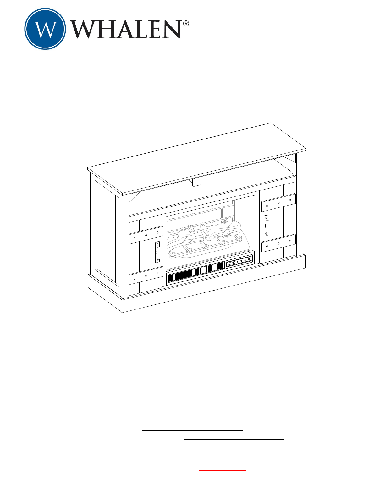
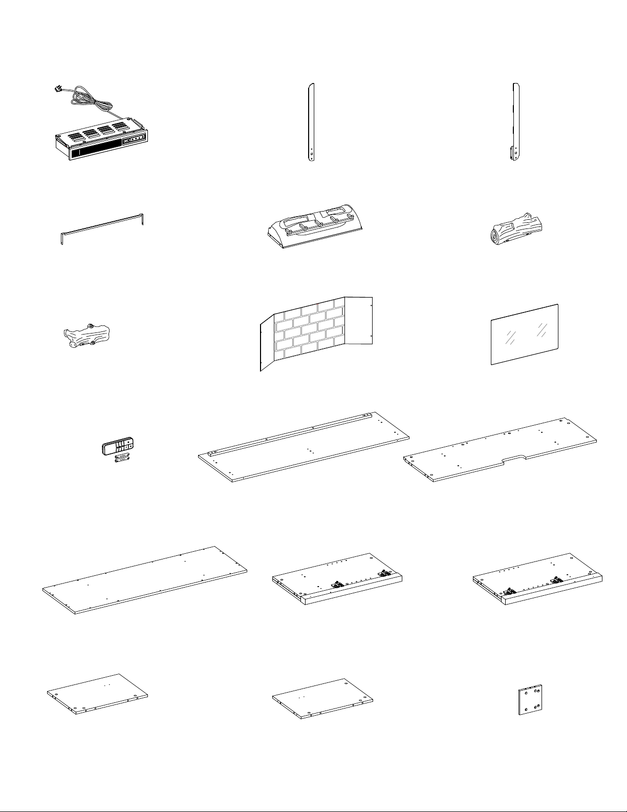
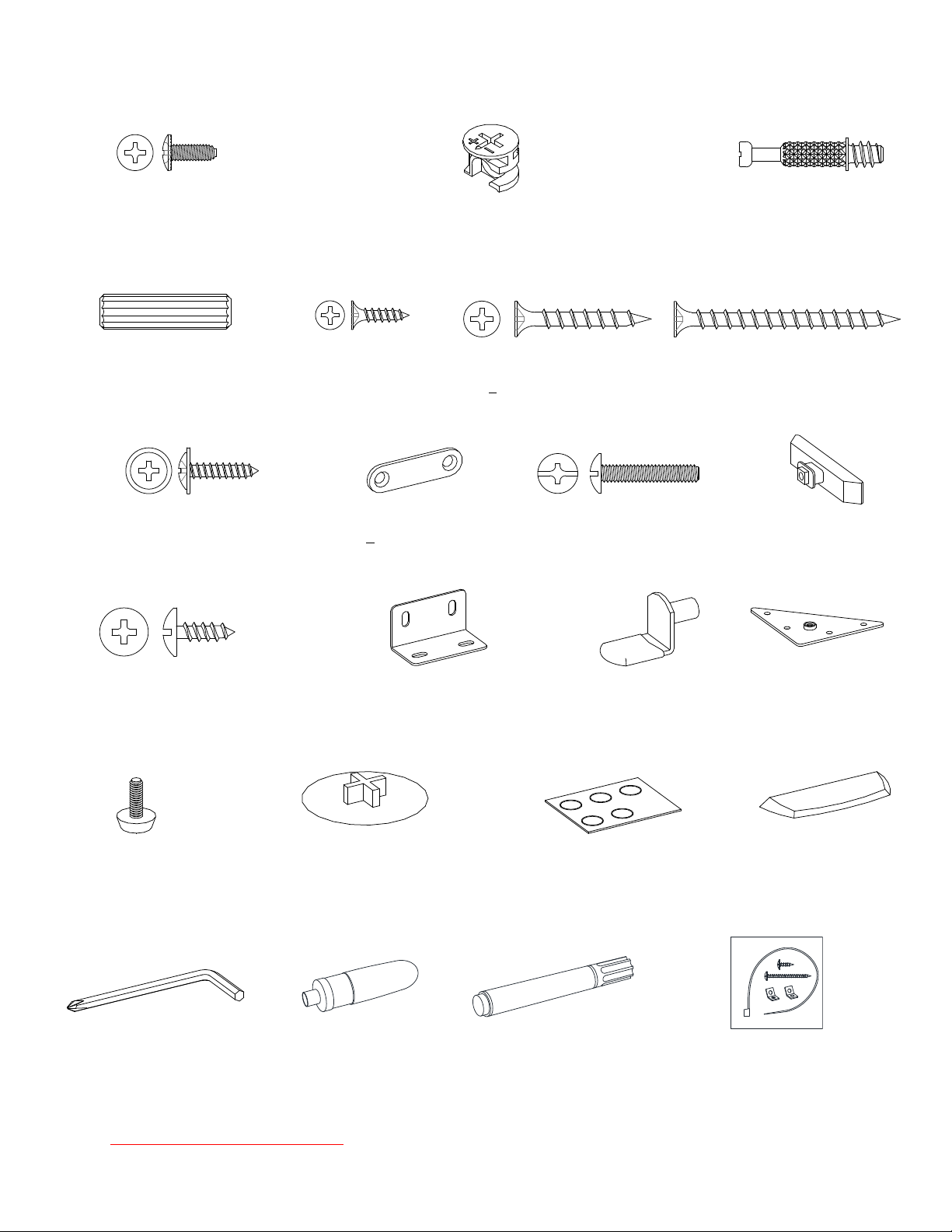
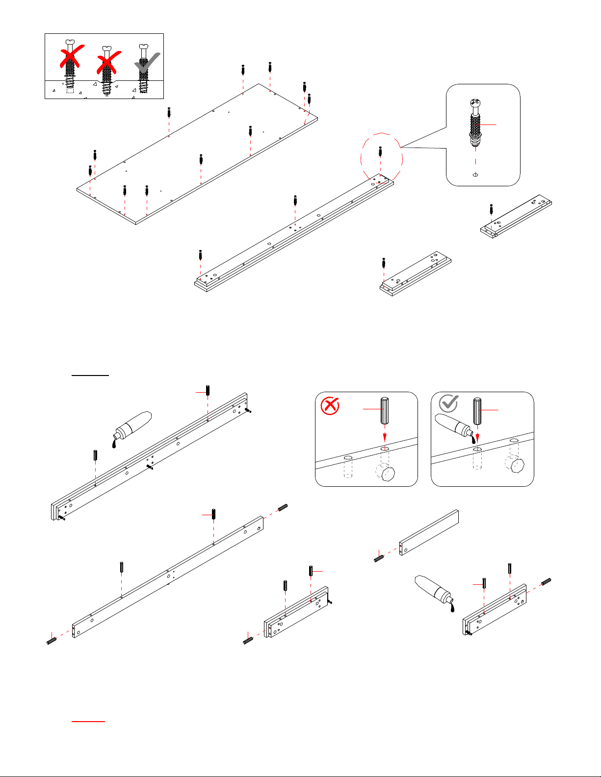
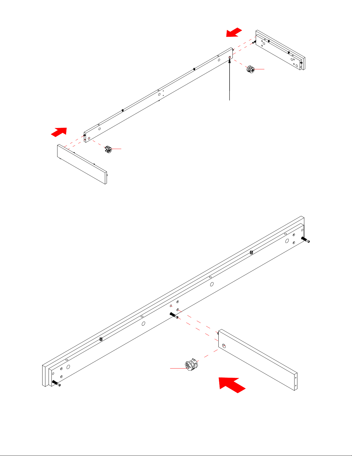
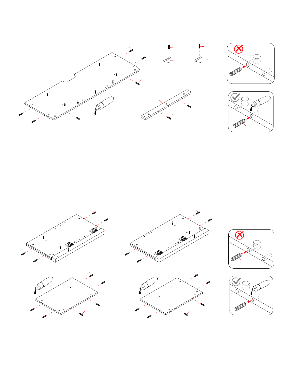
Whalen Wheatley MNFP48WTY23HLAA User manual

THIS INSTRUCTION BOOKLET CONTAINS IMPORTANT SAFETY INFORMATION.
PLEASE READ AND KEEP FOR FUTURE REFERENCE.
Date: 2023-06-12 Rev. 0001-A
Wheatley 48” Fireplace Console
Model # MNFP48WTY23HLAA
ADULT ASSEMBLY REQUIRED
If you have any questions regarding assembly or if parts are missing, DO NOT return this item to the
store where it was purchased. Please call our toll-free customer service number and have your
instructions and parts list ready to provide the model name, part name or factory number:
1-866-942-5362
Pacific Standard Time: 8:30 a.m. - 4:30 p.m., Monday - Friday
Or visit our web site 24 hours a day, 7 days a week for product assistance at
www.whalenfurniture.com
Or e-mail your request to parts@whalenfurniture.com
LOT NUMBER:
DATE
PURCHASE
D
:
/
/

2
IMPORTANT
Before you begin: Open, identify and count all parts prior to assembly. Lay out parts on a flat and
non-abrasive surface. You will need the parts identified on page 3,4 and 5 of this instruction manuals.
NOTE: IT IS VERY IMPORTANT TO USE GLUE WITH THE DOWELS. EXCESS GLUE CAN BE
WIPED OFF WITH A DAMP CLOTH.
Insert dowel at least half way by tapping lightly with a rubber mallet (not included), IF NECESSARY.
CAM LOCK SYSTEM OPERATION
HOW THE KNOCK DOWN (KD) ASSEMBLY SYSTEM WORKS
1. Screw the Cam Bolt into the pre-drilled small holes on the panel. Connect both panels together; making sure
the Cam Bolt goes into the pre-drilled hole at the end of the panel with the Cam Lock.
2. Insert the Cam Lock into the pre-drilled large hole in the panel. Make sure the arrow on the Cam Lock is
pointed towards the Cam Bolt.
3. Once the Cam Bolt is connected inside the Cam Lock, take a Phillips screwdriver (not included) and
tighten the Cam Lock clockwise.
4. Plug the Cam Lock Cover into the cross slot of the Cam Locks to conceal the cam.
You are now ready to assemble the KD unit.
How to adjust the European adjustable hinges on doors
Shipping may cause doors to go out of alignment. If you find that the doors need to be adjusted slightly,
turn the appropriate screw, as illustrated.
1. TO ADJUST DOOR FORWARD OR BACKWARD.
2. TO ADJUST DOOR TO RIGHT OR TO LEFT.
3. TO ADJUST DOOR UP OR DOWN.
1234
FINAL
43
13
GLUE
1 2
2
1
3

3
Parts and Hardware List
Please read completely through the instructions and verify that all listed parts and hardware are present
before beginning assembly.
A- Heater (Qty. 1) B- Left Upright Arm (Qty. 1) C- Right Upright Arm (Qty. 1)
D- Connector Strap (Qty. 1) E- Ember Bed (Qty. 1) F- Left Log (Qty. 1)
G- Right Log (Qty. 1) H- Wall Panel (Qty. 1) I- Glass Screen (Qty. 1)
J- Remote Control with Battery K- Top Panel L- Media Shelf
(Qty. 1) (Qty. 1) (Qty. 1)
M- Bottom Panel N- Left Side Panel O- Right Side Panel
(Qty. 1) (Qty. 1) (Qty. 1)
P- Lower Left Partition Q- Lower Right Partition R- Upper Partition Panel
(Qty. 1) (Qty. 1) (Qty. 1)

4
Parts and Hardware List
Please read completely through the instructions and verify that all listed parts and hardware are present
before beginning assembly.
S- Upper Partition Molding T- Middle Crossbar U- Middle Trim
(Qty. 1) (Qty. 1) (Qty. 2)
V- Reinforcement W- Front Skirting X- Left Skirting
(Qty. 1) (Qty. 1) (Qty. 1)
Y- Right Skirting Z- Bottom Middle Stretcher A1- Rear Skirting
(Qty. 1) (Qty. 1) (Qty. 1)
B1- Door C1- Adjustable Shelf D1- Upper Back Panel
(Qty. 2) (Qty. 2) (Qty. 1)
E1- Lower Back Panel F1- Firebox Support G1- Triangle Block
(Qty. 2) (Qty. 1) (Qty. 2)

5
Parts and Hardware List
Please read completely through the instructions and verify that all listed parts and hardware are present
before beginning assembly.
(1) M4 x 10 mm Insert Screw (2) Cam Lock (3) Cam Bolt
(Qty. 10+1 extra) (Qty. 51+2 extra) (Qty. 51+2 extra)
(4) M8 x 30 mm Wood Dowel (5) M3.5 x 12 mm Screw (6) M4 x 30 mm Screw (7) M4 x 50 mm Screw
(Qty. 47+2 extra) (Qty. 4+1 extra) (Qty. 4+1 extra) (Qty. 6+1 extra)
(8) M3.5 x 15 mm Washer Head Screw (9) Mending Plate (10) 5/32” x 22 mm Bolt (11) Handle
(Qty. 32+1 extra) (Qty. 2) (Qty. 2) (Qty. 2)
(12) M4 x 12 mm Pan Head Screw (13) L-Shaped Metal Bracket (14) Shelf Support (15) Triangle Metal Plate
(Qty. 16+1 extra) (Qty. 2) (Qty. 8+1 extra) (Qty. 2)
(16) Floor Leveler (17) Cam Lock Cover (18) Rubber Bumper (19) Acrylic Stopper
(Qty. 2) (Qty. 18+1 extra) (Qty. 4+1 extra) (Qty. 1)
Phillips Bit Hex Wrench Glue Touch-up Pen Tipping Restraint Hardware Kit (Qty. 2)
(Qty. 1) (Qty. 2) (Qty. 1) (Included in plastic bag)
Tools required (not included): Phillips screwdriver, stud finder, pencil, tape measure, power drill
and 1/8” drill bit.

6
Assembly Instructions
1. Unpack the unit and confirm that you have all the hardware and required parts. Assemble the unit on a
carpeted floor or the empty carton to avoid any scratch.
2. Securely screw 16 Cam Bolts (3) into the designated small holes on the Bottom Panel (M) and Skirting
Boards (W, X and Y) with a Phillips screwdriver.
NOTE: Screw-in cam bolts must be screwed down flush.
3. Glue 13 Wood Dowels (4) into the designated holes on the Skirting Boards (W, X, Y and A1) and
Bottom Middle Stretcher (Z).
NOTE: It is very important to use a small amount of glue on both ends of dowels and wipe away the
excess glue immediately with a damp cloth.
3
M
W
X
Y
4 4
4
4
4
4
4
Z
XY
A1
W
4
4

7
2
Y
A1
X
2
Assembly Instructions
4. Align and attach the Rear Skirting (A1) between the Side Skirtings (X and Y) by engaging 2 Cam
Locks (2). (Refer to page 2 on Cam Lock system operation supplement).
5. Attach the Bottom Middle Stretcher (Z) to the Front Skirting (W) by engaging one Cam Lock (2).
The cam lock housings
face inward.
Z
2
W

8
Assembly Instructions
6. Attach the assembled Front Skirting (W) to both Side Skirtings (X and Y) with 2 Cam Locks (2).
7. Insert two 50 mm Screws (7) through the Rear Skirting (A1) and securely screw into the Bottom Middle
Stretcher (Z).
8. Align and attach the previous assembly to the Bottom Panel (M) by engaging 11 Cam Locks (2).
X
2
WX/Y
7
A1
Z
A1
Y
WZ
X
Y
W
A1
M
2
M

9
Assembly Instructions
9. Securely screw 15 Cam Bolts (3) into the designated small holes on the Bottom Panel (M), Media Shelf
(L) and Middle Trims (U) using a Phillips screwdriver.
10. Securely screw 10 Cam Bolts (3) into the designated small holes on the Side Panels (N and O) and
Reinforcement (V) using a Phillips screwdriver
3
M
L
U
U
3
N
O
V

10
Assembly Instructions
11. Glue 10 Wood Dowels (4) into the inner holes on the Media Shelf (L), Middle Crossbar (T) and
Triangle Blocks (G1) as shown.
12. Glue 20 Wood Dowels (4) into the designated inner holes on the Side Panels (N and O) and Lower
Partition Panels (P and Q).
L
4
4
4
4
4
44
T
G1
G1
4 4
4 4
4 4
4
4
N
O
PQ

11
Assembly Instructions
13. Align and attach the Reinforcement (V) to the Media Shelf (L) by engaging 4 Cam Locks (2).
14. Using the wood dowels as a guide, orient and attach the Middle Crossbar (T) to the Media Shelf (L)
by engaging 3 Cam Locks (2).
L
V
2
L
V
2
L
T
T
L
The cam lock housings
face inward.

12
2
PQ
U
U
P/Q
U
Assembly Instructions
15. Attach the Middle Trims (U) to the Lower Partition Panels (P and Q) respectively with 4 Cam
Locks (2).
16. Orient and attach the Lower Partition Panels (P and Q) to the Media Shelf (L) by engaging 4 Cam Locks
(2).
The trims face inward and are
located at the front.
The outer edges are even
2
P
Q
L
P/Q
L

13
N
2
O
L
N/O
L
V
7
7
P
Q
O
N
2
M
M
Assembly Instructions
17. Align and attach the Left Side Panel (N) to the Media Shelf (L) and Reinforcement (V) by engaging 3
Cam Locks (2).
18. Repeat the same procedure to attach the Right Side Panel (O) at the other side.
19. Align the wood dowels inserted under the previous assembly with the large holes on the Bottom Panel
(M), and then press them together. Fasten the Bottom Panel (M) to the Side Panels (N and O) with 4
Cam Locks (2).
20. Insert four 50 mm Screws (7) through the mounting holes on the Bottom Panel (M) and securely screw
into the Lower Partition Panels (P and Q).
Floor protector
The hinge bases face inward and
are l
o
cated at
fro
nt side.

14
Assembly Instructions
21. Using the pilot holes as a guide, fasten two Triangle Metal Plates (15) at the bottom joints between the
Front Skirting (W) and Side Skirtings (X and Y) using four 12 mm Pan Head Screws (12) per plate.
22. Securely screw two Floor Levelers (16) into the threaded sockets on the Triangle Metal Plates (15). Set
the floor levelers to the correct height.
X
12
15
W
X/Y
WY
16
15
The flat surface
faces outward.

15
Assembly Instructions
23. Ask for assiatance to lift the assembled unit upright and position it near the final location.
24. Securely screw 10 Cam Bolts (3) into the designated small holes on the Top Panel (K), Media Shelf (L),
and Upper Partition Molding (S) using a Phillips screwdriver.
25. Glue 4 Wood Dowels (4) into the inner holes on the Upper Partition Panel (R).
26. Orient and attach the Upper Partition Molding (S) to the Upper Partition Panel (R) by engaging 2 Cam
Locks (2).
3
K
S
L
4
2
4
4
R
R
S

16
R
O
N
2
K
K
Assembly Instructions
27. Align and attach the assembled Upper Partition Panel (R) to the Media Shelf (L) by engaging 2 Cam
Locks (2).
28. Ask for assistance to place the Top Panel (K) onto the inserted wood dowels on the vertical panels
properly and fasten it in place by engaging 6 Cam Locks (2).
The molding is located at the front.
2
R
L
R
L

17
Assembly Instructions
29. Ask for assistance to lay down the assembled unit at its front edges.
30. Using the pilot holes as a guide, attach two Mending Plates (9) at the joints where the Middle Crossbar
(T) meets the Middle Trims (U), with two 12 mm Screws (5) per plate.
31. Now, go back and securely tighten all the cam locks and screws. Make sure that all the parts are tight
and there are no gaps between the parts. This will help keep the unit square.
32. Pick up the Upper Back Panel (D1) and align the pre-drilled holes against the upper long edge with the
pilot holes on the back edge of Top Panel (K). Fasten it in place with the provided Washer Head Screws
(8).
33. Using the pilot holes as a guide, align and attach the Lower Back Panels (E1) to the mantel frame with
16 Washer Head Screws (8).
NOTE: We recommend attaching back panel with washer head screws at the corners first.
TU
U
9
5
U
T
E1
E1
D1
8
D1/E1

18
Assembly Instructions
34. Ask for assistance to lift the assembled unit upright.
35. Align and fasten two Triangle Blocks (G1) to the front joints between the Top Panel (K) and both Side
Panels (N and O), using four 30 mm Screws (6). Securely tighten the screws with the Phillips Bit Hex
Wrench provided.
36. Attach one Handle (11) to the front of each Door (B1) with one 22 mm Bolt (10).
O
G1
N
G1
K
6
G1
N/O
K
x 2
10
B1
11

19
Assembly Instructions
37. Pick up one Door (B1) and attach the extended hinge arms to the hinge bases installed on the Left Side
Panel (N). Loosen the bolt on the back of hinge base for an easy fit.
38. Align and insert the “U” slot on hinge arm under the bolt head on the back of hinge base. Make sure that
both door hinges engage and function properly. Tighten the bolt on the hinge base to lock the hinges in place.
39. Repeat the same procedure to attach the other Door (B1) to the Right Side Panel (O).
40. Open and close the doors to make sure they are aligned and shut correctly. If necessary, adjust the
screws for a good fit.
41. Insert 4 Shelf Supports (14) into the holes at the desired height inside each side compartment. Make
sure you place the four Shelf Supports (14) at the same level to level the shelf.
42. Tilt and rest the Adjustable Shelves (C1) onto the Shelf Supports (14) properly.
Vertical
Adjustment
Horizontal
Adjustment
Depth
Adjustment
O
B1
N
B1
2
1
1
2
O
P
N
Q
C1
C1
C1
14
14

20
Assembly Instructions
43. Plug Cam Lock Covers (17) onto the visible Cams Locks to conceal the cams.
44. Stick the Rubber Bumpers (18) on the Middle Trims (U) where the Doors (B1) are in contact with.
IMPORTANT NOTE: Use hand screwdriver, not power driver to assemble fireplace insert. See BILT
for video instructions.
45. See figure A: Fasten upper 2 Insert Screws (1) through the Upright Arm (C) into the Heater (A) until
tight.
46. See figure B: Fasten lower 2 Insert Screws (1) into the Upright Arm (C) until tight.
47. Fully tighten all 4 Insert Screws (1) one final time.
48. Repeat the same process with Upright Arm (B).
WARNING: Do not lift or transport the heater by using the upright arms.
Figure A Figure B
U
U
O
18
18
U
17
N
A
C
B
C
1
A
1
C
A
1
Table of contents
Other Whalen Fireplace Accessories manuals
Popular Fireplace Accessories manuals by other brands

Travis Industries
Travis Industries 95400424 installation instructions

ICC
ICC EXCEL Installation and maintenance instructions

Valor
Valor LEGEND G3 763BPB installation instructions

Valor
Valor LEGEND G3 Series installation instructions

Heat & Glo
Heat & Glo DRIFTWOOD-C32 installation instructions

HPC
HPC El Pilot Assembly Replacement

Masport
Masport Riverstone instructions

Sirocco
Sirocco Eco4 MKIII Installation and user instructions

Valor
Valor G4 790FTV installation manual

Monessen Hearth
Monessen Hearth AVFL42RLK installation instructions

Uniflame
Uniflame W-1881 Assembly instructions

Cheminees Philippe
Cheminees Philippe RADIANTE 873 2V PR Installation & user manual