Wheeler-Rex 6600 User manual

WheelerMfg.DivRexInternationalUSAInc.
3744JeffersonRoad
Ashtabula,OH44004USA
Tel:8003217950
Fax:4409922925
wheeler@wheelerrex.com
www.wheelerrex.com

2
KeyParts4
PipeandMachineAlignment21
Changing/ReplacingtheRoller22
Changing/ReplacingtheShaft23
CopperRollGrooveSpecs23
6600PartsDiagramandList25
6601PartsDiagramandList27
MinimumandMaximumWallThickness20
ManualRollGrooveOperation6
GrooveDepthAdjustment9
WheelerRex7090PoweredOperation10
WheelerRex6790PoweredOperation14
Ridgid®300PoweredOperation15
StandardRollGrooveSpecs19
ImportantInformationandSafety3
GeneralMaintenance3
6602SteelSet29
6603R30030
6604WheelerRexBracketSet31
CopperRollGrooveKit660532
TableofContentsModel6600ManualRollGroover

3
ToolScope
TheWheelerRexModel6600RollGrooverisdesignedtoformstandardrolledgroovesinsteelandstainless
steelpipe(seepipecapacityspecifications);byeitherusingapowersourceormanually.The6600RollGroover
hasbeendesignedfor‘jobsite’stylework,notfabshoporproductionwork.Withtheratchet,youcaneasily
rollgroovepipemanually.It’swiththeextremelightweight,durabledesignthatmakesthistoolportableandeasy
touseoverhead.
Important–ReadBeforeOperating
Beforeoperatingthe6600RollGroover,readandfollowallsafetyinformation,instructionsinthismanual.
PersonalSafetyInformation
·Seriousinjuriescanoccurifalloperatinginstructions&safetyinformationisnotfollowed.
·Lossofbodypartsifglovesorclothingarecaughtinmovingparts.
·Eyeinjuriesduetoworkpiecechipsorthrownworkpiece.
·Brokenbonesfromfallenworkpieceorifmachinetipsover.
·Alwaysusepersonalprotectiveequipment,eyeglasses,safetyshoesandhardhat.
WorkAreaSafety
·Keepworkareacleanandclearofdebris.
·Keepfloordryandfreeofoiloranyslipperyliquid.
·Makesureyourworkareaiswelllit.
·Keepbystandersandchildrenawayofworkareafortheirandyoursafety.
ElectricalSafety
·Inspectcordendsforfrayedandbrokenends.Neverpulloncord.Keepawayfromsharp
objectsandexcessiveheat,andmovingparts.
·Donotuseadaptersonplugends.Plugendsshouldmatchoutlets.
·Donotusepowertoolsinwetconditions.UseaGFCIifoperatingindamplocations.
·Alwaysuseasuitableextensioncordforoutdooruse.
GeneralSafety
·Readandunderstandallinformationinoperationmanual.
·Besuretoknowallfunctionsandlocationofallfeaturesontoolpriortooperation.
GeneralMaintenance
·Priortoeachuse,inspectbothshaftandroller.Replaceifwornordamaged.
·Inspectallothermovingparts.Replaceifwornordamaged.
·Withmultipurposegrease,lubricaterollgrooveratallthreegreasefittings.
·Refertothreadingmachinemanualformaintenancepertainingtothispowersource.
ToolUseandCare
·Storeunusedtoolsawayfromchildrenoranyotheruntrainedpeople.
·UseonlyWheelerRextoolswithorincombinationwiththistool.
·Doregularmaintenanceinspections,lubricatetoolandcheckformisaligned,looseorbindingparts.
·Neverforceoroverfeedthistool.Useaccordinglytoprintedinstructions.
·AlwayshaveyourtoolservicedbyanauthorizedWheelerRexServicecenter.
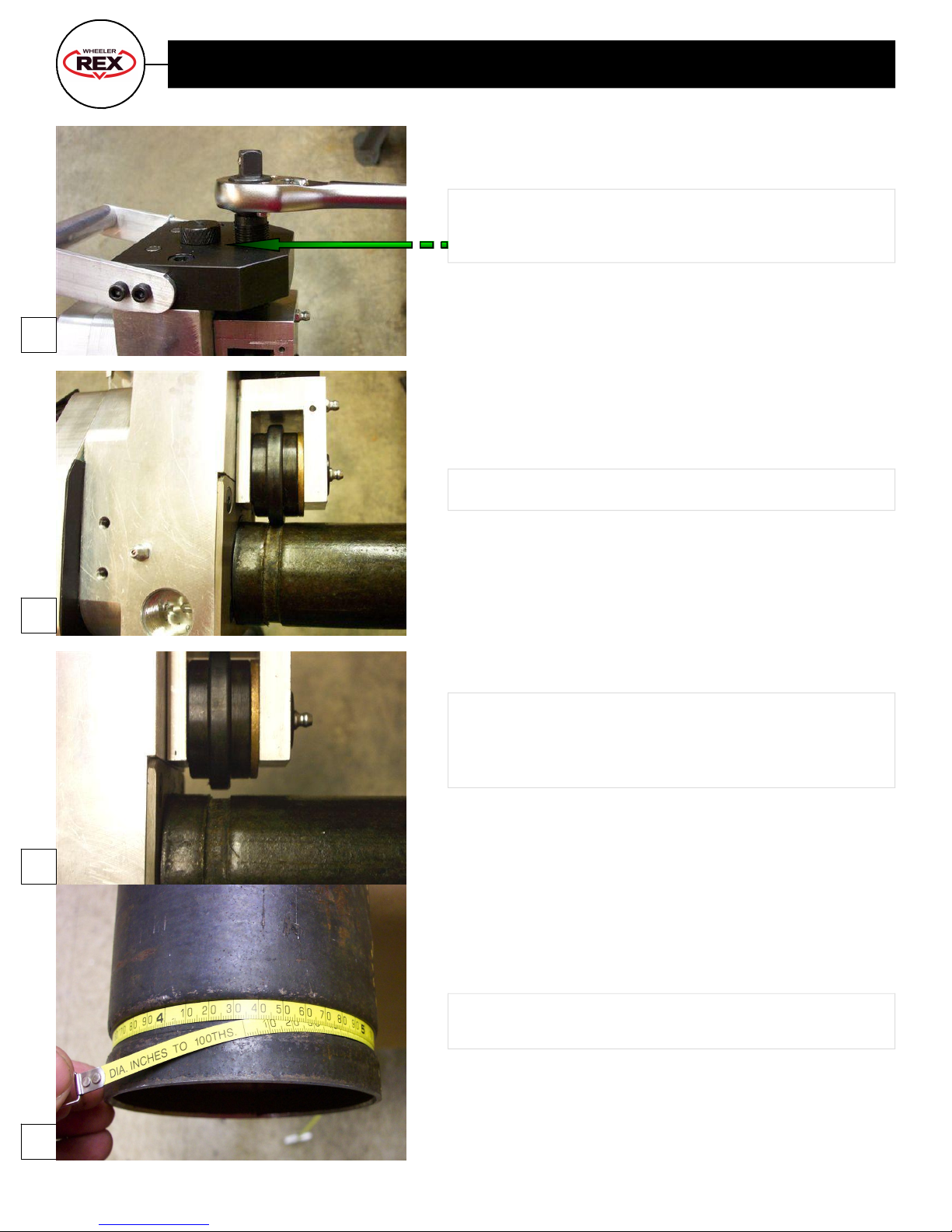
OtherRecommendedAccessories
·WheelerRex#71DiameterTape
·WheelerRex#4160TripodViseStand
·WheelerRex#851FoldingTripodPipeSupportw/heavydutyballtransferhead
PipeCapacitySpecifications
·1¼”–6”Schedule10steelpipe
·1¼”–6”Schedule40steelpipe
·1¼”–6”Schedule10stainlesssteelpipe
Important Information

4
PinionGear
GearCover
GageKeys
TopPlate
GreaseFittings
FeedScrew
Shaft
GreaseFitting
DepthAdjustmentScrew
Roller
Manual Roll Groover Key Parts Part 1

5
Manual Roll Groover Key Parts Part 2
Handle
Body
SkidPlate
Balldetent
LocatedonFeedScrewtohelpholdratcheton
Balldetent
LocatedonPinionGearShafttohelphold
ratcheton.

6
Manual Roll Groove Operation Part 1
Turnfeedscrewcounterclockwisetoraiserollerupfar
enoughtoenablepipewalltofitbetweenrollerandshaft.
FeedScrew
Roller
Shaft
Placedriveextensionontopiniongearshaft.
Placepipewallbetweenrollerandshaft.Turn
feedscrewclockwiseuntiltherollerandshaft
lightlypinchthepipewall.Theunitshouldbe
stableenoughtonotslidearoundthepipe,yet
notpinchthepipe.Pipeshouldbepushedup
againsttheskidplateontherollgroover.
1
2
3

7
Manual Roll Groove Operation Part 2
DepthGageScrew
DepthGageKey
Turnthedepthgagescrewcounterclockwise.
Theheadofthescrewshouldbehighenoughto
allowthegagekeytobeplacedunderneath.Turn
thedepthgagescrewclockwiseuntilthescrew
headtouchesthegage.
Selectdepthgageaccordingtopipediameterand
schedule.
Removethedepthgagekeyfromunderneaththe
screw.Thereshouldnowbeagapunderthe
depthgagescrewhead.
Placebentratchetonthefeedscrew.Advance
thefeedscrewwith1/4”to1/2”turnsintheclock
wisedirection.
Directionarrowsarelocatedongearcover
Afteradvancingthefeedscrew,placetheratchet
withthedriveextensionontothedriveextension.
Rotateratchetinaclockwisedirection.Direction
arrowsarelocatedaroundpiniongearshaft.
4
7
6
5

8
Manual Roll Groove Operation Part 3
RepeatSteps6and7untilthedepthadjustscrew
touchesthetopplate.Atthispointtherollgrooveis
complete.
Rollgroovecomplete.
Turnfeedscrewcounterclockwisetoreleaseroller
fromgroove.Makesurethattherollerishigh
enoughtoclearthedimpleontheinsideofthepipe.
Removerollgroovetoolfrompipe.
Measuregroovewithadiametertapeupon
completion.
8
9
10
11

9
Making Groove Depth Adjustments
Ifthegroovemeasurestoosmallortoolarge,adjustmentscanbemade.Thelinelocatedontopof
thedepthadjustmentscrewisformakingtheseadjustments.
Each1/4turnofthedepthadjustscrewwillproduce.020”inchangeonthediameterofthegroove.
Therefore,turningthescrewintheclockwisedirectionwillmakethegroovediameterlarger.
Counterclockwisedirectionwillmakethegroovediametersmaller.

10
WheelerRex 7090 Power Roll Groove Operations Part 1
Movethecarriageasclosetothechuckas
possible..
Addtheshaftextender.Therearetwo(2)set
screwtosecuretheextendertotheshaft.
Addthesupportbracketstoeachsideoftheroll
groovemainblock.Therearetwo(2)sockethead
capscrewsrequiredpersidetoholdthese
bracketson.
Openthechuckandinserttheshaftextender.
1
4
2
3

11
WheelerRex 7090 Power Roll Groove Operations Part 2
5
6
7
8
Thestabilizerbracketsshouldtouchtherailendsof
thethreadingmachine.Closethechuckonshaft
extender.
Turnfeedscrewcounterclockwisefarenoughto
allowforthepipetobeplacedbetweentheshaftand
theroller.
Turnfeedscrewclockwiseuntilthepipeislightly
pinchedbetweentheshaftandtheroller.
Turnthedepthgagescrewcounterclockwise.The
headofthescrewshouldbehighenoughtoallow
thegagekeytobeplacedunderneath.Turnthe
depthgagescrewclockwiseuntilthescrewhead
touchesthegage.Selectdepthgageaccordingto
pipediameterandschedule.

12
WheelerRex 7090 Power Roll Groove Operations Part 3
9
10
11
12
Removegagefromunderdepthadjustscrew.
Changethreaderdirectiontoreverse.
Asmachineisrunning,turnfeedscrew1/41/2turn
intheclockwisedirection.Allowpipetomakeone(1)
completerevolutionbeforeturningthefeedscrew
again.
Placebentratchetonfeedscrew.

13
WheelerRex 7090 Power Roll Groove Operations Part 4
13
14
Continuegroovinguntilthedepthadjustscrew
touchesthetopplate.
Turnthefeedscrewcounterclockwiseuntil
thereisenoughroombetweentherollerand
shafttoremovethegroovedpipe.
Measuregroovewithadiametertapeupon
completion.
15

14
WheelerRex 6790 Power Roll Groove Operations
RepeatStepsOne(1)thruFourteen(14)listedinthe7090section.
Notes:StepOne(1)andTwo(2):Notedirectionofsupportbracketsinabovepicture.
SkipStepFive(5).Supportbracketsdonotneedtotouchbarsupports.
Supportbracketdirection

15
Ridgid® 300 Powered Roll Groove Operation Part 1
4
1
2
3
Placehandlesonguiderodsandinsertshaftintothe
openchuck.
Screwhandlesintothelargethreadedholeoneach
sideofthemainblock.
Extraholesareinthemainblockforadded
accessories.Thelargeholesoneithersidearefor
stabilizerbarsforuseonthe300.Thetwo(2)small
holesareforstabilizerbracketstobeusedonREX
machines.
Two(2)smallthreadedholes.
One(1)largethreadedhole.
Openchuckonthreadingmachine.

16
Ridgid® 300 Powered Roll Groove Operation Part 2
8
7
6
5
Placebentratchetonfeedscrew.
Turnfeedscrewcounterclockwise.Allowenough
roomforthepipewalltobeplacedbetweenthe
rollerandtheshaft.
Closechuckonthethreadingmachine.Makesure
thattheshaftflatsontheshaftarealignedwiththe
chuckjaws.
Noteflatmachinedonshaft.

17
Ridgid® 300 Powered Roll Groove Operation Part 3
9
10
11
12
Insertpipebetweenrollerandshaft.Pipeendshould
betouchingskidplate.Turnfeedscrewclockwise
untilrollerlightlypinchesthepipe.
Asmachineisrunning,turnfeedscrew1/41/2turn
intheclockwisedirection.Pipeschedulewilldeter
minefeedscrewadjustment.Allowpipetomake
one(1)completerevolutionbeforetuningthefeed
screwagain.
Setmachinedirectiontoreverse.
Continuegroovinguntildepthadjustscrewtouches
thetopplate.

18
Ridgid® 300 Powered Roll Groove Operation Part 4
14
13
Turnthefeedscrewcounterclockwiseuntilthere
isenoughroombetweentherollerandtheshaftto
removethegroovedpipe.
Measuregroovewithadiametertapeupon
completion.

19
Standard Roll Groove Specifications Figure 1
Nominal
PipeSize
Dimensions
PipeOutsideDiameterO.D. A B GrooveDiameterC d
Groove
Depth
Ref.
t
Minimum
Allowable
Wall
Thickness
Maximum
Allowable
Flare
Diameter
Basic Tolerance Gasket
Seat
Groove
Width Tol.
+ +/0.03 +/0.03 Basic 0.000
11/4" 1.66 0.016 0.016 0.625 0.281 1.535 0.015 0.063 0.065 1.77
11/2" 1.9 0.019 0.019 0.625 0.281 1.775 0.015 0.063 0.065 2.01
2" 2.375 0.024 0.024 0.625 0.344 2.250 0.015 0.063 0.065 2.48
21/2" 2.875 0.029 0.029 0.625 0.344 2.720 0.018 0.078 0.083 2.98
3" 3.5 0.035 0.031 0.625 0.344 3.344 0.018 0.078 0.083 3.6
31/2" 4 0.04 0.031 0.625 0.344 3.834 0.020 0.083 0.083 4.1
4" 4.5 0.045 0.031 0.625 0.344 4.334 0.020 0.083 0.083 4.6
41/2" 5 0.05 0.031 0.625 0.344 4.834 0.020 0.083 0.095 5.1
5" 5.563 0.056 0.031 0.625 0.344 5.359 0.022 0.084 0.109 5.66
6" 6.625 0.063 0.031 0.625 0.344 6.455 0.022 0.085 0.109 6.73

20
Copper Roll Groove Specifications Figure 1
StandardRollGrooveforU.S.StandardCopperTubing
NominalSize PipeO.D. GasketSeat
A+/.03
GrooveWidth
B+/.03
GrooveDia.
C+/.03
GrooveDepth
d
Min.AllowWallThickness
t
Max.Allowed
FlareDia.
2 2.125 0.610 0.300 2.029 0.048 0.064 2.220
2.5 2.625 0.610 0.300 2.525 0.050 0.065 2.720
3 3.125 0.610 0.300 3.025 0.050 DWV 3.220
4 4.125 0.610 0.300 4.019 0.053 DWV 4.220
5 5.125 0.610 0.300 4.999 0.053 DWV 5.220
6 6.125 0.610 0.300 5.999 0.063 DWV 6.220
8 8.125 0.610 0.300 7.959 0.083 DWV 8.220
This manual suits for next models
6
Table of contents
Other Wheeler-Rex Tools manuals