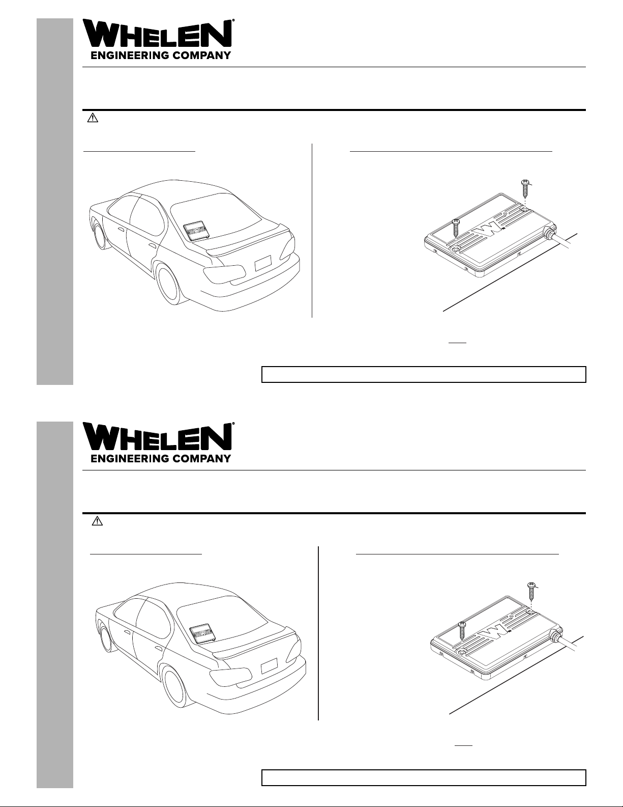
Whelen Engineering Company WeCanX V2V User manual
Other Whelen Engineering Company Control Unit manuals

Whelen Engineering Company
Whelen Engineering Company CenCom Core C399 User manual

Whelen Engineering Company
Whelen Engineering Company CenCom Core-R CEM4HC User manual

Whelen Engineering Company
Whelen Engineering Company CanTrol Troubleshooting guide

Whelen Engineering Company
Whelen Engineering Company WeCan Series User manual

Whelen Engineering Company
Whelen Engineering Company 295HFSA6 User manual

Whelen Engineering Company
Whelen Engineering Company 295SDA1 User manual

Whelen Engineering Company
Whelen Engineering Company PCC4W User manual

Whelen Engineering Company
Whelen Engineering Company E-2010 User manual

Whelen Engineering Company
Whelen Engineering Company PCCS9NP User manual

Whelen Engineering Company
Whelen Engineering Company CenCom Core-S C399S User manual

Whelen Engineering Company
Whelen Engineering Company CenCom Core C399 User manual

Whelen Engineering Company
Whelen Engineering Company WPKM1 User manual

Whelen Engineering Company
Whelen Engineering Company WPA Series User manual

Whelen Engineering Company
Whelen Engineering Company BETA1 Series User manual
Popular Control Unit manuals by other brands

Festo
Festo Compact Performance CP-FB6-E Brief description

Elo TouchSystems
Elo TouchSystems DMS-SA19P-EXTME Quick installation guide

JS Automation
JS Automation MPC3034A user manual

JAUDT
JAUDT SW GII 6406 Series Translation of the original operating instructions

Spektrum
Spektrum Air Module System manual

BOC Edwards
BOC Edwards Q Series instruction manual

KHADAS
KHADAS BT Magic quick start

Etherma
Etherma eNEXHO-IL Assembly and operating instructions

PMFoundations
PMFoundations Attenuverter Assembly guide

GEA
GEA VARIVENT Operating instruction

Walther Systemtechnik
Walther Systemtechnik VMS-05 Assembly instructions

Altronix
Altronix LINQ8PD Installation and programming manual