Page 4
The UPS64LX Strobe Power Supply, like all Whelen com-
ponents, can be installed in many different types of vehicles.
The guidelines for the installation of this product are written
so that no matter what vehicle is being used, the installation
and operation of the UPS64LX will be simple and straight
forward.
Selecting a Mounting Location...
The most common choice for a mounting area would be a
trunk or similar compartment. However, due to the wide
variety of vehicles onto which the UPS64LX could be
installed, this is not always possible. The following
guidelines will help the installer select an acceptable
alternative:
A) The UPS64LX™ should be mounted on a metal surface
to aid heat dissipation. Be sure that this surface is not
one that either generates or is exposed to excessive
heat during normal operation of the vehicle.
B) Do not select a location where the UPS64LX™ will be
exposed to potential damage from any unsecured or
loose equipment in the vehicle.
C) Be sure the area selected will not allow the UPS64LX™
to be exposed to water!
D) When routing the UPS64LX’s wires, it is important to
choose a path that will keep these wires away from
excessive heat and from any vehicle equipment that
could compromise the integrity of the wires (ex. trunk
lids, door jams, etc.).
E) When the best mounting location has been determined,
securely fasten the UPS64LX™ to it’s mounting surface
using the supplied hardware.
WARNING: The Strobe Light Power Supply is a high voltage
device. Do not touch or remove tube assembly in strobe light
head assemblies while in operation. Wait 10 minutes after dis-
connecting the unit from its power source before starting work or
troubleshooting on power supply or system.
CAUTION: As it will be necessary to drill holes into the mounting
surface, the installer MUST be sure that no vehicle components
or other vital parts could be damaged by the drilling process.
Check both sides of the mounting surface before drilling begins!
Installation...
1. Position the UPS64LX in its proposed mounting location to
ensure that it fits properly. With the UPS64LX™ in place,
insert an awl or other suitable tool into the mounting screw
area of the power supply and scribe the areas to be drilled.
2. Remove the UPS64LX™ from its mounting area and, using
a drill bit sized for a #10 sheet metal screw, drill a hole in
each of the areas scribed in the previous step.
3. Return the UPS64LX™ to its mounting location and using
the supplied #10 sheet metal screws, mount the
UPS64LX™ onto its mounting surface.
WARNING: All customer supplied wires, that connect to the
positive (+) terminal of the battery, must be sized to supply at
least 125% of the maximum operating current, and fused “at the
battery” to carry the load!
Wiring...
2. Connect the RED wire to a fuse block (customer supplied)
and then to the POSITIVE terminal on the battery.
NOTE! Although a 15 amp fuse (customer supplied) is required
to be used in the fuse block, do not install the fuse until all of the
wire connections are completed.
3. Connect the BLACK wire to the factory chassis ground
adjacent to the battery.
CAUTION: Reversing polarity (Reversing Positive and Ground-
wires) during the installation of a strobe light power supply, will
blow either the 15 amp fuse incorporated into the unit, or the
inline 15 amp fuse located on the positive (+) wire connected to
the power source.
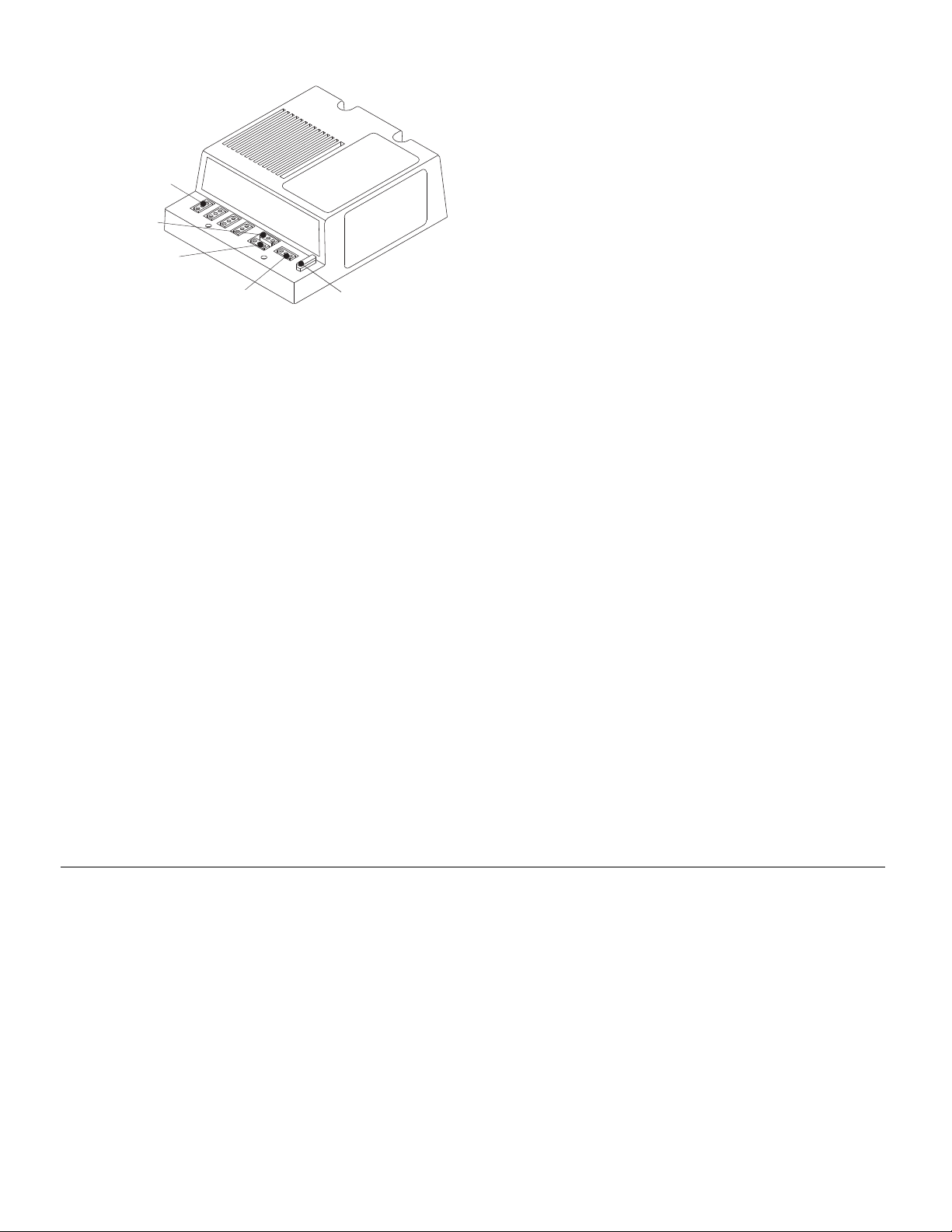
3POSITION
STROBE LIGHT
CONNECTORS
3POSITION
CONTROLCONNECTOR
3POSITION
PATTERN SELECTION
CONNECTOR
3POSITIONSOCKET
POWERINPUT CONNECTOR.
15 AMPFUSE FOR STROBE
POWERSUPPLY PROTECTION
UPS-64LX
POWER SUPPLY
™
The Micro-Edge™
is a dual Xenon tube, 270º remote strobe light head assem-
bly. Each unit is either designed for left or right side mounting
on vehicle. The cable assembly used to connect the Micro-
Edge™ light head assemblies to the Model UPS-64LX™
Strobe Light Power Supply, is a 6 conductor cable 20 feet
long. One end of the cable is connected on the inside of the
Micro-Edge™, and on the other end to factory installed 3 pin
connectors. Each one of the Micro-Edge™ light head assem-
blies is labeled underneath to indicate on which side of the
vehicle they should be mounted. When connecting the con-
nectors to the strobe light power supply, observe the color
coding and proper positioning of these connectors.
(See Wiring Diagram, Page 2.)
NOTE: During installation, when passing the cable through metal
surfaces, remove the burrs from the edges of the holes and if
possible use rubber grommets to protect the cable. It is also
advisable to support the cable with ty-wraps, cable clamps, or
any other means to prevent the cable from shifting around or
putting tension on the connectors.
The wiring assembly which connects the UPS-64LX™ strobe
power supply to the switch control assembly is a 5 conductor
cable assembly, 8 feet long.