manuals.online logo
Brands
  1. Home
  2. •
  3. Brands
  4. •
  5. WHITECROFT LIGHTING
  6. •
  7. Light Fixture
  8. •
  9. WHITECROFT LIGHTING Marine LF Manual

WHITECROFT LIGHTING Marine LF Manual

Whitecroft Lighting Limited
Burlington Street, Ashton-under-Lyne, Lancashire OL7 0AX
Telephone +44 (0)870 5 087 087 Facsimile: +44 (0)870 5 084 210
Registered No. 3848973 England Registered Office:
As above
Marine LF
Installation Leaflet
February 2017 - Rev B
GENERAL INFORMATION
1) A qualified electrician, in accordance with IEE wiring regulations, should carry
out connection to mains wiring.
2) Ensure that the rated voltage and frequency requirements are compatible with
the available mains supply.
3) Cleaning of reflectors and lenses should be carried out using clean, soft and
lint free cloths and anti-static cleaning fluid
4) Do not carry out high voltage insulation test, i.e. 500/1000v this may damage
internal components.
5) We recommend use of a high temperature Copper Paste on all screws that
need to be accessed during maintenance process, this will prolong the life of
the fixings and reduce the force required to remove the screws.
TECHNICAL SUPPORT
Tel: 0161 331 5700
E-mail: [email protected]
www.whitecroftlighting
.com
General Maintenance
To access the inside of the luminaire you will need to remove the
3 screws with a size 2.5 allen key. Remove the front of the
luminaire to get access to the inside of product. Reverse the
process to put close.
PK/LEAF/MARINLF
Please note: All images shown are for illustration purposes and should be used
as a reference guide only.
The marine LF is a small in ground surface uplighter with an
external driver which must be ordered separately. This product
can be run in series at 3.8W per head with a max of 4
luminaires at a max length of 50m (from driver to last fitting).
V
Height
mm Width
MAX
mm
Diamiter
Front
mm
86 130 120
F
ig. 3
Installation Sequence
1. Identify the locations for luminaires and driver. A maximum
of 4 luminaires can be operated from one driver.
2. Prepare a suitably sized hole for each luminaire with
sufficient drainage below.
3. Run cables suitable for outdoor use between driver and
luminaire(s) in a trench. Cables should be protected in line
with the latest IEE regulations.
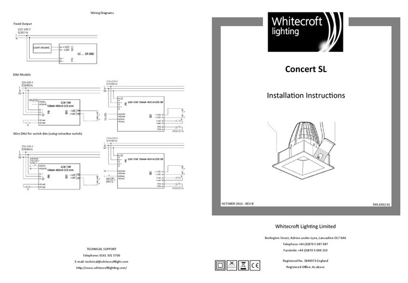
4. Wiring should be in line with Figure 3 opposite.
5. Remove the luminaire from its packaging, making sure all
products are in good condition before installing.
6. Undo the 3 screws on the front face of the luminaire and
then 2 further screws inside and lift out the led module and
bracket.
7. Pull in a 2 core cable (max 4mm²) through the grommet on
the side of the luminaire which will be wired into the
connection block later. Continue the wiring on to other
luminaires in the circuit if required follow the wiring diagram,
(Fig 4). The cable’s outer sheath should be cut back just
inside the luminaire and the 2 individual cores left long.
8. Locate the luminaire housing into the prepared hole and
pour concrete to fill the hole. The luminaire is supplied with a
plastic levelling disc which can be removed once the
concrete has set. Ensure all cable is in place before pouring
in the concrete. See Fig. 3
9. Wire the 2 core cable into the connection block (Fig 4).
10. Replace the LED module and bracket using the 2 screws
removed earlier.
Each Marine LF luminaire is shipped in two
separate packages:
Before commencing installation, check contents
of all cartons to ensure that all components are
present and in good condition.
1) Main body
2) External Driver in waterproof box
(Order separately)
F
ig
.
4
11. Replace the outer frame using the 3 Allen screws, tightening
gradually and in sequence. Ensure the gasket is clear of any dirt or
debris to maintain a watertight seal. (Power tools must not be used
to prevent damaging screw threads).
12. Select a location for the driver housing noting there are 4 screw
points in the back of the box if required. Ensure any screw holes
are protected from water ingress using appropriate seals.
13. Bring the 2 core cable from the luminaire(s) into the driver
housing through the side grommet and wire into the connection
block. (Fig.2)
14. Bring a 3 core mains supply into the driver housing and wire
into the connection block and isolate the earth cable in a secure
and safe manner.
15. Close the driver housing, ensuring the seals are clean and free
of debris using the correct sequence of tightening so the seal is
correct.
16. The mains supply can then be connected.
3.8W POWERLED (MAX 4)
S
p
ecification

Other WHITECROFT LIGHTING Light Fixture manuals

WHITECROFT LIGHTING FOIL single optic User manual

WHITECROFT LIGHTING

WHITECROFT LIGHTING FOIL single optic User manual

WHITECROFT LIGHTING Concert EX1S OR3 User manual

WHITECROFT LIGHTING

WHITECROFT LIGHTING Concert EX1S OR3 User manual

WHITECROFT LIGHTING Concert SL User manual

WHITECROFT LIGHTING

WHITECROFT LIGHTING Concert SL User manual

WHITECROFT LIGHTING Marine SD Manual

WHITECROFT LIGHTING

WHITECROFT LIGHTING Marine SD Manual

WHITECROFT LIGHTING MSU Surface User manual

WHITECROFT LIGHTING

WHITECROFT LIGHTING MSU Surface User manual

WHITECROFT LIGHTING Egress Exit Manual

WHITECROFT LIGHTING

WHITECROFT LIGHTING Egress Exit Manual

WHITECROFT LIGHTING Concert EX2S User manual

WHITECROFT LIGHTING

WHITECROFT LIGHTING Concert EX2S User manual

WHITECROFT LIGHTING Duo 3 Evo User manual

WHITECROFT LIGHTING

WHITECROFT LIGHTING Duo 3 Evo User manual

Popular Light Fixture manuals by other brands

Chauvet PK PAR56C user manual

Chauvet

Chauvet PK PAR56C user manual

Lightolier SV T5 STRIP specification

Lightolier

Lightolier SV T5 STRIP specification

UEBEX PLANELO user manual

UEBEX

UEBEX PLANELO user manual

Spa Electrics RETRO Installation & owner's manual

Spa Electrics

Spa Electrics RETRO Installation & owner's manual

Eaton Crouse-hinds series Installation & maintenance information

Eaton

Eaton Crouse-hinds series Installation & maintenance information

Klus INTER Mounting instructions

Klus

Klus INTER Mounting instructions

Lightolier 40600H1 Instructions for installation

Lightolier

Lightolier 40600H1 Instructions for installation

Quilt Display Products WALL HANGER instructions

Quilt Display Products

Quilt Display Products WALL HANGER instructions

Cooper Lighting METALUX 248VHO Specifications

Cooper Lighting

Cooper Lighting METALUX 248VHO Specifications

Lightolier Calculite ProSpec PA4P3075 specification

Lightolier

Lightolier Calculite ProSpec PA4P3075 specification

EuroLite TMH-X4 user manual

EuroLite

EuroLite TMH-X4 user manual

Gima LUXIFLEX 30754 Use and maintenance book

Gima

Gima LUXIFLEX 30754 Use and maintenance book

Light Emotion FLAT0505R User instruction manual

Light Emotion

Light Emotion FLAT0505R User instruction manual

BARO Ontero XR In-Track Series Installation and operating instructions

BARO

BARO Ontero XR In-Track Series Installation and operating instructions

RSA Lighting COMBOLIGHT LV Series LV220MH Specifications

RSA Lighting

RSA Lighting COMBOLIGHT LV Series LV220MH Specifications

Energetic Lighting E1STA Series installation instructions

Energetic Lighting

Energetic Lighting E1STA Series installation instructions

Lightolier VRB SERIES 1'x4 specification

Lightolier

Lightolier VRB SERIES 1'x4 specification

Raytec VARIO 2 VAR2-w8-1 quick start

Raytec

Raytec VARIO 2 VAR2-w8-1 quick start

manuals.online logo
manuals.online logoBrands
  • About & Mission
  • Contact us
  • Privacy Policy
  • Terms and Conditions

Copyright 2025 Manuals.Online. All Rights Reserved.