manuals.online logo
Brands
  1. Home
  2. •
  3. Brands
  4. •
  5. Wibre
  6. •
  7. Controllers
  8. •
  9. Wibre 5.0670.59.52 User manual

Wibre 5.0670.59.52 User manual

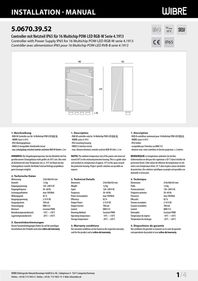
INSTALLATION  MANUAL
5.0670.59.52
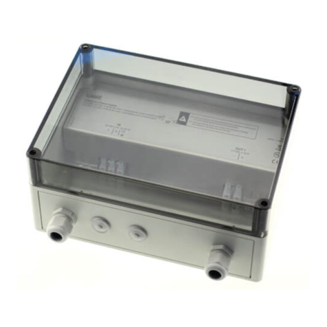
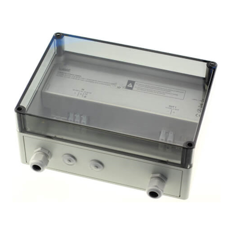
Controller mit Netzteil IP65 für 32 Multichip POW-LED RGB-W Serie 4.2013
Controller with Power Supply IP65 for 32 Multichip POW-LED RGB-W serie 4.2013
Contrôller avec alimentation IP65 pour 32 Multichip POW-LED RVB-B serie 4.2013
1. Description
· RGB-W controller only for 32 Multichip POW-LED RGB-W,
WIBRE series 4.2013
· IP65 mounting housing
· DMX512 interface in/out
· max. distance between controler and last RGB-W-Unit ≤ 2 m
NOTE:The ambient temperature (ta) of the power unit must not
exceed 50°C in the enclosed protective housing.This is a guide value
and reached at a temperature of approx. 35°C in the space around
the protective housing. Project-specific solutions are possible on
request.
2. Technical Details
Dimension: 360x245x165 mm
Weight: 2,5 kg
Input: 120–240V-AC
Frequency: 50–60 Hz
Power Consumption: max 200Watt
Efficiency: 82 %
Output Power: 2-55V-DC
Output Current: 700 mA
Control: DMX 512
Dimming Method: Constant PWM
Operating temperature: -10°C – +50°C
Storage temperature: -20°C – +85°C
3. Warranty conditions
Our warranty conditions can be found on the respective warranty
card for the product and at wibre.de/warranty.
1. Description
· RGB-B contrôlleur seulement pour 32 Multichip POW-LED RVB-B,
WIBRE series 4.2013
· IP65 boîtier
· compatible par l‘interface au DMX 512
· distance max. entre contrôleur et dernier projecteur ≤ 2 mètres
REMARQUE: La température ambiante (ta) du bloc
d‘alimentation ne doit pas être supérieure à 50 °C dans le boîtier de
protection fermé. Cette valeur de référence de température est att-
einte à une température d‘env. 35 °C dans la pièce autour du boîtier
de protection. Des solutions spécifiques au projet sont possibles sur
demande si nécessaire.
2. Technique
Dimensions: 360x245x165 mm
Poids: 2,54 kg
Tension primaire: 120–240V-AC
Fréquence primaire: 50–60 Hz
Puissance: max 200Watt
Efficacité: 82 %
Tension secondaire: 2-55V-DC
Courant secondaire: 700 mA
Control: DMX 512
Dimmable: Constant PWM
Température de régime: -10°C – +50°C
Température du stockage: -20°C – +85°C
3. Dispositions de garantie
Nos conditions de garantie se trouvent sur la carte de garantie
correspondante du produit et sous wibre.de/warranty.
WIBRE Elektrogeräte Edmund Breuninger GmbH & Co. KG · Liebigstrasse 9 · 74211 Leingarten/Germany
Telefon: +49 (0) 7131 9053-0 ·Telefax: +49 (0) 7131 9053-19 · E-Mail: [email protected] 1/4
1. Beschreibung
· RGB-W-Controller nur für 32 Multichip POW LED RGB-W,
WIBRE Serie 4.2013
· IP65 Montagegehäuse
· DMX512-kompatible Schnittstelle in/out
·max.Leitungslängezwischen Controlerund letzter RGB-W-Einheit≤ 2 m
HINWEIS: Die Umgebungstemperatur (ta) des Netztteils darf im
geschlossenem Schutzgehäuse nicht größer als 50°C sein. Dies wird
als Richtwert bei einer Temperatur von ca. 35°C im Raum um das
Schutzgehäuse erreicht. Bei Bedarf sind auf Anfrage projektbezo-
gene Lösungen möglich.
2. Technische Daten
Abmessung: 360x245x165 mm
Gewicht: 2,5 kg
Eingangsspannung: 120–240V-AC
Eingangsfrequenz: 50–60 Hz
Leistungsaufnahme: max 200Watt
Wirkungsgrad: 82 %
Ausgangsspannung: 2-55V-DC
Ausgangsstrom: 700 mA
Steuereingang: DMX 512
Dimmart: Constant PWM
Betriebstemperaturbereich: -10°C – +50°C
Lagertemperaturbereich: -20°C – +85°C
3. Garantiebestimmungen
Unsere Garantiebedingungen finden Sie auf der jeweiligen
Garantiekarte des Produkts und unter wibre.de/warranty.
254
165
360
≈ 28
ta max
35°C
IP65
INSTALLATION  MANUAL
2/4 WIBRE Elektrogeräte Edmund Breuninger GmbH & Co. KG · Liebigstrasse 9 · 74211 Leingarten/Germany
Telefon: +49 (0) 7131 9053-0 ·Telefax: +49 (0) 7131 9053-19 · E-Mail: [email protected]
4. Anschlußbelegung · Wiring Diagram · Raccordement · 5.0670.59.52
ACHTUNG: Anschluss der Netzteile muss stromlos erfolgen, da
sonst Entladungen im Netzteil zur Schädigung der LED führen
können. Es darf keine Primärspannung anliegen.
HINWEIS: Die Installation eines bauseitigen Überspannungs-
schutzes nach DIN VDE 0100-443, DIN VDE 0100-534 und EN 62305
wird empfohlen.
ATTENTION: The power supply must be connected without power,
since otherwise discharges in the power supply unit may damage the
LED. Primary voltage must not be present.
NOTE: Installation of customised surge protection in accordance with
DIN VDE 0100-443, DIN VDE 0100-534 and EN 62305 is recommended.
ATTENTION: Les blocs d‘alimentation doivent être raccordés hors tensi-
on, sinon des décharges dans le bloc d‘alimentation peuvent détériorer les
LED. Aucune tension primaire ne doit être présente.
REMARQUE: L‘installation d‘un système anti-surtension local conforme
aux normes DIN VDE 0100-443, DIN VDE 0100-534 et EN 62305 est recom-
mandée.
max 2 m
1-40 - schwarz/black
Erde/Ground/Terre
Null/Zero/Cero
Phase 230 V
G - gelb-grün/yellow-green
M20 M16 M16 M32
OUT 2OUT 1
5.0670.59.52 RGB-W-Controller
IP65, 12 V-DC, max 200W, DMX in/out, max 32Multichip POW-LED RGB-W, Serie 4.2013
W443-026-V02
IN PRIM
120-240 V-AC, 50-60 Hz
L N
DMX IN DMX OUT
+ – + –GND GND
FAN
LÜFTER
39
LOWER LEVEL
UPPER LEVEL
40 PE 9 10 19 20 29 30
NTC
N/AN/A
DMX-Adress
DMX-Adress
preinstalled
0 0 1
customized
87654321 18 1716 15 14 13 1211
OUT 3
28 2726 25 24 23 2221
OUT 4
38 3736 35 34 33 3231
ta:
-10°C – +50°C Pb
DE | ANSCHLUSS DES SCHEINWERFERS MUSS STROMLOS ERFOLGEN.
ES DARF KEINE PRIMÄRSPANNUNG ANLIEGEN.
EN | THE SPOTLIGHT MUST BE CONNECTED WITHOUT POWER.
NO PRIMARY VOLTAGE MAY BE APPLIED.
110
INSTALLATION  MANUAL
5. Anschluss und Einstellungen · Connection and settings · Raccordement et réglages
WIBRE Elektrogeräte Edmund Breuninger GmbH & Co. KG · Liebigstrasse 9 · 74211 Leingarten/Germany
Telefon: +49 (0) 7131 9053-0 ·Telefax: +49 (0) 7131 9053-19 · E-Mail: [email protected] 3/4
Connection
The power supply pack is connected to the power supply via the AC
terminal.
The Output terminal is used for connecting an RGB-W-type spotlight
with 700mA from theWibre 4.2013 series.
The DMX signal is fed into the power supply pack via DMX-in, and
the DMX signal is emitted via DMX-out.
Address setting
The DMX start address is preset to 001.The optionally available
USB toolbox (art. no. 38.4.20504.990, incl. software) can be used
to configure various DMX start addresses and dimming curve on
the controller (RDM-compatible).The setting of the output current
and NTC value must remain unchanged. See also manual of the USB
Toolbox.
Note: Use of the remote control 5.0690.09.55 possible.
Raccordement
Le bloc d‘alimentation est connecté à la tension d‘alimentation via la
borne CA.
La borne Output est utilisée pour le raccordement d‘un projecteur
Wibre de la série 4.2013 en exécution RVB-B avec 700mA.
Le signal DMX est intégré dans le bloc d‘alimentation via DMX-in et
le signal DMX est émis via DMX-out.
Réglage de l‘adresse
L‘adresse de départ DMX est préréglée à 001. LaToolbox USB
disponible en option (réf. 38.4.20504.990, logiciel inclus) permet de
configurer différentes adresses de départ DMX et courbe de grada-
tion sur le contrôleur (compatible RDM). Le réglage du courant de
sortie et de la valeur NTC doit rester inchangé.Voir aussi le manuel
de laToolbox USB.
Note: Utilisation de la télécommande 5.0690.09.55 possible.
Anschluss
Über die Klemme AC in wird das Netzteil mit derVersorgungsspan-
nung verbunden.
Die Klemme Output dient zum Anschluss eines Scheinwerfers der
Wibre Serie 4.2013 in RGB-W-Ausführung mit 700mA.
Über DMX-in wird das DMX-Signal in das Netzteil eingespeist, über
DMX-out wird das DMX Signal ausgegeben.
Adresseinstellung
Die DMX-Startadresse ist auf 001 voreingestellt. Über die optional
erhältliche USB-Toolbox (Art-Nr. 38.4.20504.990, inkl. Software)
können u.a. verschiedene DMX-Startadressen und Dimming Kurve
am Controler (RDM-fähig) konfiguriert werden. Die Einstellung des
Ausgangsstrom und NTC-Wert muss unverändert bleiben. Siehe auch
Manual der USBToolbox.
Hinweis:Verwendung der Fernbedienung 5.0690.09.55 möglich.
6. DMX512 Anschluß · DMX512 Wiring Diagram · Raccordement DMX512
DMX-Steuergerät/
DMX-Controler
RGBW-Controler
Bsp./example
DMX Adress
001
RGBW-Controler
Bsp./example
DMX Adress
005
RGBW-Controler
Bsp./example
DMX Adress
009
letzter/last
RGBW-Controler
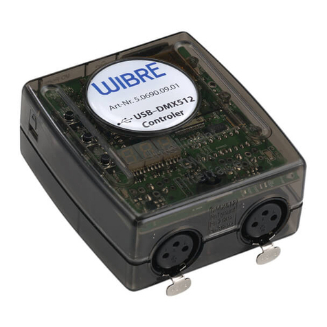
z.B. USB-DMX-Controler: 5.0690.09.01
DMX/RDM Verkabelung/Anschluß
DMX-Verkabelung ist beispielhaft dargestellt. Um DMX-Reflexionen
zu vermeiden, sollte der letzte Controler zusätzlich mit einem
Abschlußwiderstand 120Ohm an„DMX in“ versehen werden.
Bei Verwendung von mehr als 32 RGB-W-Controlern oder DMX-
Kabellängen >300m zwischen Steuergerät und RGBW-Controler
müssen Repeater bzw. Booster eingesetzt werden.
Hinweis: Messung des DMX-Signals teilweise notwendig
DMX/RDM cabling/connection
DMX cabling is shown as an example.To avoid DMX reflections,
the last controller should additionally be provided with a 120Ohm
terminating resistor at„DMX in“.
When using more than 32 RGB-W controllers or DMX cable lengths
>300m between controller and RGBW controller repeaters or
boosters must be used.
Note: measurement of DMX signal partly necessary
Câblage/connexion DMX/RDM
Le câblage DMX est montré à titre d‘exemple. Pour éviter les
réflexions DMX, le dernier contrôleur doit être équipé en plus d‘une
résistance de terminaison de 120Ohm à„DMX in“.
Si vous utilisez plus de 32 contrôleurs RGB-W ou si la longueur du
câble DMX est supérieure à 300 m entre le contrôleur et le contrôleur
RGBW, vous devez utiliser des répétiteurs ou des boosters.
Note: la mesure du signal DMX est partiellement nécessaireraduit
avec www.DeepL.com/Translator (version gratuite)
W977 - Stand 09.20 - Technische Änderungen vorbehalten - Für Druckfehler übernehmen wir keine Haftung
7. Wichtige Hinweise
(Bei Nichtbeachtung folgender Punkte,
entfällt die Garantie.)
•Vor der Installation müssen alleTeile aufTransportschäden
überprüft werden!
• Jegliche Montage-, Installations- und Elektroarbeiten müssen von
qualifiziertem Fachpersonal durchgeführt werden.
• ZurVermeidung von Gefährdungen darf eine beschädigte äußere
flixible Leitung dieser Leuchte ausschließlich vom Hersteller,
seinem Servicevertreter oder einer vergleichbaren Fachkraft
ausgetauscht werden.
• Die Lichtquelle dieser Leuchte darf nur vom Hersteller oder einem
von ihm beauftragten Servicetechniker oder einer vergleichbar
qualifizierten Person ersetzt werden.
• ZurVermeidung von Fremdrost nur Edelstahlwerkzeug verwenden!
• Die Kabellänge der Leuchten ist so zu wählen, dass man nicht im
Wasser oder feuchten Umgebung verlängern muss. Spätere Rekla-
mationen aufgrund dessen können nicht akzeptiert werden.
• Es dürfen nur originale Wibre-Betriebsgeräte verwendet werden.
• Ein Montageabstand von 10 cm zwischen Betriebsgeräten wird
dringend empfohlen, um wechselseitiges Erhitzen zu vermeiden.
• Anschluss der Betriebsgeräte muss stromlos erfolgen, da sonst
Entladungen im Netzteil zur Schädigung der LED führen können.
Es darf keine Primärspannung beim Wechsel der LED anliegen.
• Beim Anschließen der Leuchte die Polung beachten! Eine falsche
Polung kann dem LED-Modul schaden.
• Die Installation eines bauseitigen Überspannungsschutzes nach
DINVDE 0100-443, DIN VDE 0100-534 und EN 62305 wird
empfohlen.
• Bitte achten Sie auf Maßnahmen gegen ESD (Elektrostatische
Entladung) während aller Arbeiten am Scheinwerfer, Betriebsgerät
und LED.
7. Important information
(If the following points are disregarded,
the guarantee expires.)
• Before installation, all parts must be checked for transport damage!
• All fitting, installation and electrical work must be performed by
qualified specialist staff.
•To avoid any hazards, a damaged external flexible cable of this
luminaire should only be replaced by the manufacturer, his service
representative or a comparable specialist.
•The light source of this luminaire may only be replaced by the
manufacturer or a service technician appointed by him or a compa-
rably qualified person.
• Only use stainless steel tools to avoid external rust!
•The cable length of the lights should be chosen in such a way that
it is not necessary to extend in water or moist environments. Later
complaints resulting from this cannot be accepted.
• Only original Wibre operating units may be used.
• An installation distance of 10 cm between operating devices is
urgently recommended in order to avoid mutual heating up.
•The operating devices must be connected without power, as
otherwise discharges in the power supply may cause the LED to
be damaged. No primary voltage may be applied when changing
the LED.
• Note polarity when changing the lights!The wrong polarity can
damage the LED module.
• It is recommended that the customer install an overvoltage pro-
tection in accordance with DINVDE 0100-443, DINVDE 0100-534
and EN 62305.
• Please comply with all anti-ESD (electrostatic discharge) measures
during all work on the spotlight, operating device and LED.
7. Remarques importantes
(La garantie s‘éteint en cas de
non-respect des points suivants)
• L‘absence d‘avaries de transport doit être vérifiée avant
l‘installation !
•Tous les travaux de montage et d‘installation, ainsi que les travaux
électriques, doivent être réalisés par du personnel qualifié.
• Pour éviter tout danger, un câble flexible externe endommagé du
projecteur ne peut être remplacé que par le fabricant, son représen-
tant de service ou un spécialiste qualifié.
• La source lumineuse de ce liminaire ne peut être remplacée que par
le fabricant ou un technicien de service désigné par lui ou par une
personne ayant une qualification comparable.
• Afin d‘éviter tout dépôt de rouille, utiliser exclusivement des outils
en acier inoxydable !
• La longueur de câble des lampes doit être choisie de telle sorte à ce
qu‘il ne soit pas nécessaire de la prolonger dans de l‘eau ou dans un
environnement humide.Toute réclamation ultérieure à ce motif ne
sera pas acceptée.
• Seuls des équipementsWibre originaux doivent être utilisés.
• Une distance de montage de 10 cm entre les équipements est
vivement recommandée afin d‘éviter un réchauffement mutuel.
• Le raccordement des équipements doit être effectué sans courant,
sans quoi des décharges dans le bloc d‘alimentation pourraient
entraîner une détérioration des LED. Aucune tension primaire ne
doit être établie lors du changement des LED.
• Lors du raccordement des lampes, respecter la polarité ! Une erreur
de polarité peut endommager le module de LED.
• L‘installation d‘une protection contre la surtension par le client
conforme aux normes DINVDE 0100-443, DIN VDE 0100-534 et
EN 62305 est recommandée.
•Veuillez respecter les mesures contre la décharge électrostatique
durant tous les travaux sur des projecteurs, équipements et LED.
INSTALLATION  MANUAL

Other Wibre Controllers manuals

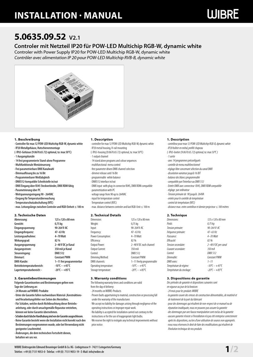
Wibre 5.0690.09.01 User manual

Wibre

Wibre 5.0690.09.01 User manual

Wibre 5.0635.19.52 User manual

Wibre

Wibre 5.0635.19.52 User manual

Wibre 5.0635.09.52 User manual

Wibre

Wibre 5.0635.09.52 User manual

Wibre 5.0670.19.24 User manual

Wibre

Wibre 5.0670.19.24 User manual

Wibre 4.1913 Series User manual

Wibre

Wibre 4.1913 Series User manual

Wibre 5.0620.19.52 User manual

Wibre

Wibre 5.0620.19.52 User manual

Wibre 5.0635.09.52 User manual

Wibre

Wibre 5.0635.09.52 User manual

Wibre 5.0690.09.05 User manual

Wibre

Wibre 5.0690.09.05 User manual

Wibre 5.0670.19.52 User manual

Wibre

Wibre 5.0670.19.52 User manual

Popular Controllers manuals by other brands

YOKOGAWA UTAdvanced UP55A technical information

YOKOGAWA

YOKOGAWA UTAdvanced UP55A technical information

intensity WDC-120G/WK(A) Service manual

intensity

intensity WDC-120G/WK(A) Service manual

Superwind SCR 48 V manual

Superwind

Superwind SCR 48 V manual

Emerson XM678D Operation and installation manual

Emerson

Emerson XM678D Operation and installation manual

iNels IM2-140M Manual instructions

iNels

iNels IM2-140M Manual instructions

3Ware 9550SXU-12 - PCI-X-to-Serial ATA II Hardware RAID... user guide

3Ware

3Ware 9550SXU-12 - PCI-X-to-Serial ATA II Hardware RAID... user guide

Halma ALICAT SCIENTIFIC PC quick start guide

Halma

Halma ALICAT SCIENTIFIC PC quick start guide

Plasmatronics PL40 Reference manual

Plasmatronics

Plasmatronics PL40 Reference manual

Afag SE-24 operating instructions

Afag

Afag SE-24 operating instructions

EnOcean Omnio UPJ230/12 manual

EnOcean

EnOcean Omnio UPJ230/12 manual

Swagelok RS2 user manual

Swagelok

Swagelok RS2 user manual

Norac Gregson Maverick 120 Series installation manual

Norac

Norac Gregson Maverick 120 Series installation manual

ActronAir LR7-1W Operation manual

ActronAir

ActronAir LR7-1W Operation manual

Honeywell PRO-2200 installation manual

Honeywell

Honeywell PRO-2200 installation manual

Sartorius CCx-L series operating instructions

Sartorius

Sartorius CCx-L series operating instructions

CD Automation REVO M 3PH user manual

CD Automation

CD Automation REVO M 3PH user manual

M-system MSP4C instruction manual

M-system

M-system MSP4C instruction manual

Danfoss ECL Comfort 310 installation guide

Danfoss

Danfoss ECL Comfort 310 installation guide

manuals.online logo
manuals.online logoBrands
  • About & Mission
  • Contact us
  • Privacy Policy
  • Terms and Conditions

Copyright 2025 Manuals.Online. All Rights Reserved.