WideBand 6000 series User manual

WideBand IP
Telep
hone
User’s Manual
Models 6000/7000
WideBand Corporation
4/21/2008

2
Table of Contents
Introduction ...................................................................................................................................... 4
Hardware Overview .................................................................................................................................. 4
Software Overview .................................................................................................................................... 4
Keypad Interface ................................................................................................................................ 5
Configure the IP Phone....................................................................................................................... 6
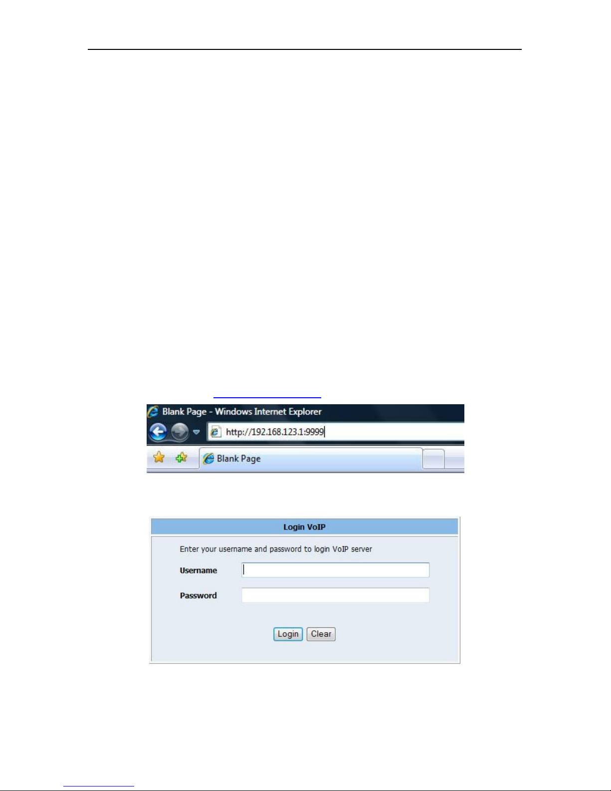
First Time Lo in ......................................................................................................................................... 6
Default Reset from Keypad ....................................................................................................................... 7
Default Settin .......................................................................................................................................... 7
Application Example .......................................................................................................................... 7
SIP-to-SIP Callin /Answerin ..................................................................................................................... 7
SIP to Direct IP Callin ............................................................................................................................... 8
Direct IP to Direct IP Callin /Answerin .................................................................................................... 8
Direct IP to Direct IP Callin within a NAT Router ..................................................................................... 8
3-Way Conference Call, Call Waitin , Call Hold ........................................................................................ 9
3-Way Conference Callin Application ................................................................................................. 9
Call Waitin Application ........................................................................................................................ 9
Call Hold Application ............................................................................................................................. 9
Call Transfer .......................................................................................................................................... 9
Call Forward .......................................................................................................................................... 9
Phone Configuration ........................................................................................................................ 1
System Information ................................................................................................................................. 10
Phone Book ............................................................................................................................................. 10
Phone Settin s ........................................................................................................................................ 11
Call Forwardin ................................................................................................................................... 11
SNTP Settin ........................................................................................................................................ 12
Volume Settin .................................................................................................................................... 13
DND Settin ......................................................................................................................................... 13
Call Waitin Settin ............................................................................................................................. 13
Dial Plan .............................................................................................................................................. 14
Network .................................................................................................................................................. 15
IP Phone User Manual

3
WAN Settin s ...................................................................................................................................... 15
LAN Settin s ........................................................................................................................................ 16
DDNS Settin ....................................................................................................................................... 16
VLAN Settin s ...................................................................................................................................... 17
PPTP Settin s ...................................................................................................................................... 17
SIP Settin s .............................................................................................................................................. 18
Service Domain ................................................................................................................................... 18
Port Settin s ........................................................................................................................................ 19
Codec Settin s..................................................................................................................................... 19
Codec ID Settin .................................................................................................................................. 20
DTMF Settin ...................................................................................................................................... 20
RPort Settin ....................................................................................................................................... 20
Other Settin s ..................................................................................................................................... 20
NAT Trans ................................................................................................................................................ 21
STUN Settin ....................................................................................................................................... 21
Others...................................................................................................................................................... 21
Auto Confi uration Settin ................................................................................................................. 21
ICMP Settin ....................................................................................................................................... 21
System Authority ..................................................................................................................................... 22
Save Chan es .......................................................................................................................................... 22
Update ..................................................................................................................................................... 22
Reboot ..................................................................................................................................................... 23
Troubleshooting Configuration ......................................................................................................... 23
The LCD is showin “Ethernet Error!” ..................................................................................................... 23
The LCD is showin “No Service” ............................................................................................................ 23
DO NOT HEAR DIAL TONE? ..................................................................................................................... 23
Copyright © 2008 WideBand Corporation. All Rights Reserved. 04.08

4
Network Protocol
Tone
•
IP v1 (RFC 2543), v2 (RFC 3261)
• IP/TCP/UDP/RTP/RTCP
• IP/ICMP/ARP/RARP/ NTP
• TFTP Client/DHCP Client/PPPoE Client
• Telnet/HTTP erver
• DN Client
• NAT/DHCP erver
• Ring Tone
• Ring Back Tone
• Dial Tone
• Busy Tone
• Programming Tone
Phone
Function
Codec
• Volume Adjustment
• peed Dial Key
• Phone Book
• Flash
• G.711:64kb/s (PCM)
• G.723.1:6.3k / 5.3kb/s
• G.726:16k / 24k / 32k / 40kb/s (ADCPM)
• G.729A:8kb/s (C -ACELP)
• G.729B:adds VAD & CNG to G.729
IP Assignment
• tatic IP
• DHCP
• PPPoE
Voice Quality
ecurity
• VAD: Voice activity detection
• CNG: Comfortable noise generator
• LEC: Line echo canceller
• Packet Loss Compensation
• Adaptive Jitter Buffer
• HTTP 1.1 basic/digest authentication for Web setup
• MD5 for IP authentication (RFC 2069/RFC 2617)
Qo
• To
F
ield
Call Function
NAT Traversal
• Call Hold
• Call Waiting
• Call Forward
• Caller ID
• 3-way conference
• TUN
Configuration
• Web Browser
• IVR/Keypad
DTMF Function
Firmware Upgrade
• In
-
Band DTMF
• Out-Band DTMF
• IP Info
• TFTP
• HTTP
IP erver
• Registrar erver (three IP accounts)
• Outbound Proxy
IP Phone User Manual
1
Introduction
This user’s manual is for the WideBand IP Telephone, models 6000 and 7000. This user’s manual wi
ll
explain the IVR instruction and web configuration for the IP phone. Before using the IP p
hone, some setup
processes are required to make the phone work properly. Please refer to the Setup
Menu for further
information.
1.1 Hardware Overview
The IP phone has the following interfaces for Networking, and one power connector.
Two RJ
-
45 networking interface
s
These two interfaces support 10/100Mps Fast Ethernet.
WAN: Connect to the ADSL modem or router.
LAN: Connect to your PC computer. You can then connect to the Internet through the Internet S
haring
function of the phone adapter.
1.2 Software Overview

5
Key Name
Description
1
“,”, “!”, “?”, “1”, “
-
“
2
“2”, “a”, “b”, “c”, “A”, “B”, “C”
3
“3”, “d”, “e”, “f”, “D”, “E”, “F”
4
“4”, “g”, “h”, “i", “G”, “H”, “I”
5
“5”, “j”, “k”, “l”, “J”, “K”, “L”
6
“6”, “m”, “n”, “o”, “M”, “N”, “O”
7
“7”, “p”, “q”, “r”, “s”, “P”, “Q”, “R”, “ ”
8
“8”, “t”, “u”, “v”,
“T”, “U”, “V”
9
“9”, “w”, “x”, “y”, “z”, “W”, “X”, “Y”, “Z”
0
“0”,
“space”
*
“*”, “.”, “:”, “@”
#
tart dialing process
TRAN FER
Transfer to the other phone number
REDIAL
Redial the same number again
HOLD
Put the call on Hold
MUTE
Mute your side of the conversation
DND
Do Not Disturb functionality
OK
OK, accept setting
DEL
Delete a word or phone number
UP/DOWN
The up and down keys
LEFT/RIGHT
The left and right keys
MENU
how phone configuration menu
PK
Turn on/off peaker Phone
Line1
–
Line3
Available conversation lines
M1
–
M5
The 5 speed dial numbers
Conf
Three
-
way conferencing
Call In
The list of incoming calls
Call Out
The list of outgoing calls
Volume +/
-
Alter volume settings
IP Phone User Manual
2 Keypad I
nterface

6
IP Phone User Manual
3
Configure the IP Phone
The IP phone provides a built-in web server, so you can use a web browser to configure the p
hone.
First, open a browser and type the IP address of the phone, specifying port 9999. Example
:
http://192.168.123.1:9999
The default LAN port IP is 192.168.123.1, with a DHCP s
erver enabled. The default WAN port has
DHCP client enabled; the IP would be automatically assigned if it is connected to a network with
a
DHCP server.
3.1
First Time Login
STEP 1
-
Power Up and Connect the Phone
•
Connect the
WAN Port to a NAT Router or ADSL Modem using a Category 5 network
cable. Then connect the LAN Port to a PC, also using a Category 5 network cable.
•
Connect the 9V power adapter to the phone’s power socket.
•
The LCD Panel s
hould then light up, showing the date, time, and “No Service” if a SIP
account is not yet set up.
•
Pick up the phone, and the LCD Panel will show “IP Dialing…”. You should hear a ring back
tone. If not, please make sure the RJ-45 WAN port is connected properly.
STEP 2
–
Set Up the VoIP Account
•
To find the phone’s IP address from the phone’s keypad, press
the MENU key, then arrow
down to the “4. Network” option and hit ENTER. Then, arrow down to the “5. Status
” and hit
ENTER. The MENU key is used for escape, and the ENTER key for selection. The defau
lt
IP address is 192.168.123.1.
•
Next, from your PC, open a browser (Internet Explorer), and enter “http://<IP address of IP
Phone>:9999” (e.g.
http://192.168.123.1:9999
”
) as follows:
•
The default login settings are a user named “root”, with the password “test”.
There is
another, limited account named “user”, also with the password “test”. If you use the root
account to log in, you can configure all of the setti
ngs.
•
Click “SIP Settings”->”Account Settings” to set up a SIP account in your IP p
hone.

7
IP Phone User Manual
Please refer to
section
5.5 for details.
Once you change the setting in the Web Management
interface, please remember to click the “Submit” button on that page.
Then, you will need to
save the settings.
•
The LCD panel will show the date, time, and registered <phone number>
after successful
SIP registration.
STEP 3
–
Make your First Call
•
Pick up the handset; you should now hear a dial tone.
•
Enter the phone number you would like to call, optionally ending with a ‘#’ (e.g. 1003#). The
‘#’tells the phone to call the number immediately. Dialing without # will not call until the auto
dial timer (default=5 seconds) elapses.
3.2
Default Reset from Keypad
To restore
the factory defaults using the phone’s keypad, press MENU, and arrow down to the “7.
Administrator” option, and press ENTER. Then, arrow down to the “3. Default setting” option, and
press ENTER. Finally, select “1. Load default”. The LCD panel will read Loading Program,
and
System Initialized. Please use the MENU key for escape, and the ENTER key for selection.
Then,
reboot the phone (option 7 in the Administrator menu).
3.3
Default Setting
LAN IP Address:
192.168.123.1
WAN IP Address:
Dynamic Address/DHCP
Web Management Page
Login Name: root
Password: test
4
Application Example
4.1 SIP-to-
SIP Calling/Answering
Applications:
Both parties are registered to a SIP server with either fixed real IP or private IP behind a
NAT router.
The SIP-to-SIP calling works when both calling and answering parties are registered to a
SIP server
with
given registered phone numbers.

8
IP Phone User Manual
Configurations:
•
Select “DHCP Client”, and bridge “ON” in the “Network / Network settings” page
•
Remember to click the “Submit” button,
•
Select Active “ON” in the “SIP settings / Service Domain” page
•
Enter the Register Name, Register Password, Proxy Server, and Outbound Proxy,
•
Select “ON” in “NAT settings / STUN setting” page, if Outbound Proxy is NOT available.
•
Upon successful SIP registration, the LCD will show registered <phone number>.
Callings:
•
Pick up the phone, and you should hear a dial tone.
•
Press 16
88# or 1688 to call the party with the registered SIP phone number 1688. Note that
the # key will dial out the number immediately. Dialing without # will not dial out until the auto
dial timer (default=5 seconds) elapses.
4.2
SIP to Direct IP Calling
Applications:
The application is for the calling party with an ADSL connection. The calling party is registered to a
SIP
server with either a fixed real or private IP, behind a NAT router. The answering party has a
fixed real
IP.
Configurations:
•
Same as in Example 4.1
•
Select “ON” in “NAT settings / STIN setting” page, if Outbound Proxy is NOT available.
•
Upon successful SIP registration, the LCD will show registered <phone number>.
Calling
:
•
Press Hand-Free key for speakerphone, and you should hear a dial tone.
•
Press 211*21*191*4# or 211*21*191*4 to call the party with the real IP address of
211.21.191.4. In a moment, you should hear a ring back tone, and wait for the VoIP called
party to answer.
4.3
Direct IP to Direct IP Calling/Answering
Applications:
The applications are for ADSL connection without a NAT router. Both parties have fixed real IP
addresses
.
SIP server registrations are not required in this application.
Configurations:
•
Select “Fixed IP”, and bridge “ON” in the “Network / Network settings” page
•
Enter the items of IP, Subnet Mask, and Gateway IP
•
Click the “Submit” button
Callings:
•
Pick up the phone, and you should hear a dial tone.
•
Press 211*21*191*4# or 211*21*191*4 to call the party with the real IP address of
211.21.191.4. Note that # key will dial out the number immediately. Dialing without # will not
dial out until the auto dial timer (default=5 seconds) elapses
. In a moment, you should hear a
ring back tone, and wait for the VoIP called party to answer.
4.4 Direct IP to Direct IP Calling within a
NAT Router
Applications:
For the calling party with an ADSL connection behind a NAT router, this d
irect IP calling can work when
the answering parties have
fixed private IP addresses within the same VPN network, or with fixed real
IP addresses:

9
IP Phone User Manual
Configurations:
•
Select “Fixed IP”, and bridge “ON” in the “Network / Network settings” page
•
Enter the items of IP, Subnet Mask, and Gateway IP
•
Click the “Submit” button
Callings:
•
Pick up the phone, and you should hear a dial tone.
•
Press 192*168*1*51# or 192*168*1*51 to call the party with the private IP address of
192.168.1.51. Press 211*21*191*4 to call the party with the real IP address of 211.21.191.4.
In a moment, you should hear a ring back tone, and wait for the called party to answer.
4.5 3-
Way Conference Call, Call Waiting, Call Hold
4.5.1 3-
Way Conference Calling Application
This is for 3-way conference call among Parties A, B, and C. Three parties are registered to a
SIP
server with either fixed real IP or private IP. The Flash/Transfer key is used to switch to the other
phone line or HOLD, and is quite useful for the 3
-
way conference call and the call waiting function.
Cal
ling:
•
Make a phone call from Party A to the first phone number Party B.
•After the first call is established, press HOLD key (or Flash key) from Party A to hold the call,
and Party A should hear a dial tone.
•Make another phone call from Party A to the second phone number Party C.
•
After the second call is established, press CONF key from Party A to join in Party B for a
three-way conference call.
4.5.2
Call Waiting Application
When a new call is coming while you are talking, you can push the HOLD / FLASH key to switch to the
new call. You can push the HOLD / FLASH key t
o switch between the two calls.
4.5.3
Call Hold Application
You can push the HOLD key to hold the current call for a while, then
push HOLD key again to resume
talking.
4.5.4
Call Transfer
You can transfer the current call to another user using the Call Transfer function
.
•
While Party A is having a phone call with Party B, and Party A would like to transfer the call
to Party C.
•
Party A should press HOLD key, a dial tone will
then be heard. Party A should then press
TRANSFER key, followed by Party C’s number and a “#” number.
•
Then Party A’s call will end, and Party C’s phone will
ring. Once Party C picks up the call, he
can speak to Party B.
Alternative Way to Transfer a Call
•
While Party A is having a phone call with Party B, and Party A would like to transfer the call
to Party C.
•
Party A will press the TRANSFER key, and a dial tone will be heard. Party A will
then dial
Party C’s number. Once a Waiting tone is heard, Party A should hang up.
•
Party C’s phone will ring. Once Party C picks up the call, he can speak to Party B.
4.5.5
Call Forward
You can forward incoming call
s
to a third
-
party
.
•
Set up the Call Forward Number using the Web Configuration (Refer to 3.2.1), or u
sing
the LCD Menu (“Phone Setting” -> “Call Forward”)
•
Press the FORWARD key to enable Call Forwarding

10
IP Phone User Manual
5
Phone Configuration
5.1
System Information
When you login the web page, you can see the phone’s current system information, such as
the
firmware version, company
name, etc. You will also see a menu of configuration categories on the left
side.
5.2
Phone Book
The phone book contains Speed Dial settings. If you want to use speed dial, just press
the speed dial
number (from 0~9), then press “#”.
Entry Name: Speed dial number
Number or URL: Real address to be dialed
Check the examples for details.

11
IP Phone User Manual
Example:
Example 1: Name 203; URL 192.168.123.1
If a user dialed “203#”, the phone would dial 192.168.123.1.
Example 2: Name: 206; URL: 17476433364
If a user dialed “206#”, the phone would dial out to (747) 643-3364.
Example 3: Name: 301; URL: 192.168.1.202:5062
If
a
user dialed
“202#”
, the phone would dial out
to 192.168.1.2:5064.
5.3 Phone Settings
Phone Settings contains Call Forwarding settings, along with SNTP, Volume, Do Not Disturb
, Caller
ID, and
Call Waiting configurations.
5.3.1
Call Forwarding
You can set up the phone number you want to forward in this page. There are three type
s of
forwarding modes: All Forward, Busy Forward, and No Answer Forward.

12
IP Phone User Manual
5.3.1.1
All Forward
All incoming call
s will be forwarded
to the number you choose. You can input the name and the phone
number in the URL/Number field.
5.3.1.2
Busy Forward
If you are on the phone, incoming calls will be forwarded to the number you choose.
You can input the
name and the phone number in the URL field.
5.3.1.3
No Answer Forward
If you do not answer the phone, incoming calls will be forwarded
to the number you choose. You can
input the name and the phone number in the URL field.
You will also need to specify the number of
rings before the call is forwarded.
5.3.2 SNTP S
etting
You can set up SNTP server IP addresses to automatically get date and time information.
You can
also set your time zone, and how often you would like to sync the time.

13
IP Phone User Manual
5.3.4
DND Setting
This setting stands for “Do Not Disturb,” and blocks all incoming calls. You can configure this to
always block calls, or to block calls just for a certain amount of time.
Always Block: All incoming calls will be blocked until this feature is disabled.
Block Period: Set an amount of time specified by “From” and “To”.
5.3.3 Volume S
etting
There are several volume configu
ration options here. The range of valid values is given beside each
field. For example, a range of “(0~14)” indicates that any value between 0 and 14 (inclusive) is valid.
5.3.6
Call Waiting Setting
You can enable or disable Call Waiting. When you are talking with someone, if there is an
incoming
call, and call waiting is enabled, you will hear the call waiting tone.

14
IP Phone User Manual
5.3.7
Dial Plan
Example 1:
Drop prefix: No, Replace rule 1: 002, 8613+8662
1: If what you dialed begins with 8613, “002” is added to the beginning; so the actual
number dialed
would be [002+8613+xxx].
2: If what you
dialed begins with 8662, “002” is added to the beginning; so the actual number dialed
would be [002+8663+xxx].
Example 2: Drop prefix: Yes, Replace rule 2: 006, 002+003+004+005+007+009
1: If what you
dialed begins with 002, the number “002” would be replaced with “006”; so the actual
number dialed would be [006+xxx].
2: If what you dialed begins with 003, the number “003” would be replaced with “006”; so the act
ual
number dialed would be [006+xxx].
Example 3: Drop prefix: No, Replace rule 3: 009, 12
1: If what you
dialed begins with 12, the number “12” would be prefixed by number “009”; so the actual
number dialed would be [009+12+xxx].
Example 4: Drop prefix: No, Replace rule 4: 007, 5xxx+35xx+21xx
1: If what you
dialed begins with 5, followed by any 3 number, the number would be prefixed by “007”;
so the actual number dialed would be [007+5xx].
2: If you dialed 534, the number 5 is only followed by two numbers
, so it does not match the dialing
rule, and the actual number dialed is still 534.
3: If what you
dialed begins with 35, followed by any two numbers, it would be prefixed by “007”; so the
actual number dialed would be [007+35xx].
4: If you dialed 358822,
the number 5 is only followed by two numbers, so it does not match the dialing
rule, and the actual number dialed is still [358822].

15
IP Phone User Manual
5.4.1
WAN Settings
You can configure the IP Phone Network setting in this page.
5.4.1
.1
Mode
There are two modes
for the WAN port: Bridge or NAT. Bridge mode: The two WAN and LAN Ethernet
ports will be bridged and transparent. NAT mode: The
embedded NAT will be enabled. The IP phone
comes with a default static IP address of 192.168.1.100. You may select a proper I
P type for your
network requirements.
5.4.1
.2
NAT Settings
To enable embedded NAT, you must set mode of WAN port to “NAT”. This embedded NAT is useful
for ADSL users without a
NAT router, and it separates the WAN port from the LAN port to perform
router IP address translation. For the WAN port, please select a proper IP type:
DHCP Client (default): Automatically get an assigned IP from the DHCP server.
PPPoE: This is a
common way to connect to your ISP through ADSL. Enter the username and
password your ISP provided.
Fixed IP: Assign a static IP address to that network interface.
MAC settings
: This must be different between the LAN and WAN. The defaults should be
acceptable.
5.4
Network
In Network you can check the Network status, configure the Network and DDNS settings.
On this
screen you will find information about
the current settings of both the LAN and WAN network
interfaces.

16
IP Phone User Manual
5.4.2
LAN Settings
5.4.2
.1
LAN Setting
In this section you can configure the IP address and the subnet mask of the LAN adapter.
5.4.
2
.2
DHCP Server
There is a built-in DHCP server in the phone a
dapter. The default is enabled. The range of IP
addresses to be assigned is specified by the Start IP and End IP fields. The Lease T
ime field specifies
the amount of time before DHCP expires for a given client.
5.4.3
DDNS Setting
You can configure the DDNS setting o
n this page. You need to have the DDNS account and input the
information properly. If you have a DDNS account with a public IP address,
others can call you via the
DDNS account. Now most VoIP applications work through a SIP Proxy Server.

17
IP Phone User Manual
5.4.4 VLAN Setting
s
VLAN
s can be used to separate VoIP traffic from other kinds of traffic, and give it a higher priority
. This
is one wa
y
to guarantee Quality
-
of
-
Service within a private network
.
5.4.5
PPTP Settings
Here you can connect the phone to a VPN (PPTP) Server. Using a VPN, you
can connect to a SIP
Server (SIP Proxy or IP PBX) inside a private network, or make a secure phone call.
PPTP Server: The VPN Server to connect to.
PPTP Username/Password: Enter your username and password for the VPN account.

18
IP Phone User Manual
5.5
SIP Settings
This section will cover configurations such as the Service
Domain, Port Settings, Codec Settings, RTP,
and RPort Settings.
5.5.1
Service Domain
You may register up to three SIP accounts in the IP phone. You can make calls through the first SIP
account, and receive calls from all three. The following figure shows a single example setup.
Display Name:
The name to be displayed on your phone.
User Name: Enter the username configured on the VoIP server.
Register Name: Enter the Register Name configured for your account on the VoIP server.
Register Password: Enter the VoIP server’s account password corresponding to your username.
Domain Server: Enter the Domain server given by your VoIP server.
Proxy Server: Enter the proxy server; this is usually your VoIP server.
Outbound Proxy: This can be left blank, as it is usually the same as the proxy server.
Subscribe for MWI: Click On if your VoIP server supports Voice Mail notification.
Once the status is “Registered”, you have successfully registered with the VoIP server.

19
IP Phone User Manual
5.5.2
Port Settings
Here you can set up the SIP and RTP port numbers. Each ISP provider may
have different
SIP/RTPport settings, so please refer to the ISP to set the port numbers correctly.
5.5.3
Codec Settings
You can set up Codec priority, RTP packet length, and VAD on this page.
Please follow the
recommendations of your ISP to configure these settings.

20
IP Pho
ne User Manual
5.5.4
Codec ID Setting
Sometimes multiple VoIP devices with different codec IDs will cause interoperability issues. If you
have
trouble communicating with someone, make sure you are using the same codec IDs.
5.5.5
DTMF Setting
Here you can configure your DTMF settings. The options are RFC 2833, Inband DTMF, and Send
DTMF SIP Info. Please configure this based on your VoIP Provider’s recommendation.
5.5.6
RPort Setting
Here you can enable or disable RPort. Please configure this according to your ISP
’
s recommendation.
5.5.7
Other Settings
You will find some miscellaneous SIP settings here. For the text fields, the range of valid values is
shown on the right. Notable options here include the QoS settings. For these options, higher values
specify a higher priority.
This manual suits for next models
1
Table of contents
Popular IP Phone manuals by other brands

Swissvoice
Swissvoice ePure quick guide

Samsung
Samsung SMT-I3105 user guide

Polycom
Polycom SoundPoint IP 550 Configuring

Grandstream Networks
Grandstream Networks GRP26 Series Configuration guide

Grandstream Networks
Grandstream Networks GRP2601/P/W Quick installation guide

New Rock Technologies
New Rock Technologies NRP1012 user manual