widos 4900 CNC 3.5 User manual

Ku nst sto ffschweißtechn i k
WIDOS Einsteinstr. 5 Phone +49 (0) 71 52 99 39 - 0
. Dommer Söhne GmbH D-71254 Ditzingen-Heimerdingen Fax +49 (0) 71 52 99 39 - 40
ebsite: www.widos.de Email: info@widos.de
Headquarters: D-71254 Ditzingen-Heimerdingen Country court Stuttgart HRB 200973 Managing director: Jürgen Dommer
Working Instructions
Translation
Heating element butt welding machine
with CNC control unit
WIDOS 4900 CNC 3.5
Keep for further use!

Ku nst sto ffschwei ßtec hni k
Product identification
02.08.2011 orking Instructions IDOS 4900 CNC 3.5 Page 2 of 68
Model: Heating element butt welding machine
with CNC control unit
Type: IDOS 4900 CNC 3.5
Serial number, year of construction: see type lable
Customer Entries
Inventory-no.:
Place of working:
Order o spare parts and sales service
Address o Manu acturer WIDOS
. Dommer Söhne GmbH
Einsteinstr. 5
D -71254 Ditzingen-Heimerdingen
Phone: ++49 7152 / 99 39 - 0
Fax: ++49 7152 / 99 39 - 40
Address of the Subsidiary Companies:
IDOS GmbH WIDOS
An der iesenmühle 15 . Dommer Söhne AG
St. Gallerstr. 93
D - 09224 Grüna / Sachsen CH – 9201 Gossau
Telefon: ++49 (0) 3 71 / 8 15 73 - 0 Telefon: ++41 (0) 71 / 388 89 79
Telefax: ++49 (0) 3 71 / 8 15 73 - 20 Telefax: ++41 (0) 71 / 388 89 73

Ku nst sto ffschwei ßtec hni k
Introduction
02.08.2011 orking Instructions IDOS 4900 CNC 3.5 Page 3 of 68
Purpose o the document
These working instructions give you information about all important questions which refer to the
construction and the safe working of your machine.
Just as we are, you are obliged to engage in these working instructions, as well.
Not only to run your machine economically but also to avoid damages and injuries.
Should questions arise, contact our service team in the factory or in our subsidiary companies.
e will help you with pleasure.
According to our interest to continuously improve our products and working instructions, we
kindly ask you to inform us about problems and defects which occur in exercise.
Thank you.
Structure o the working instructions
This manual is arranged in chapters which belong to the different using phases of the machine.
Due to this structure, the searched informations can be easily found.
02.08.2011 WIDOS
. Dommer Söhne GmbH
Einsteinstraße 5
D-71254 Ditzingen-Heimerdingen
All rights reserved
Reprinting only allowed with permission of the corporation.
Any changes prior to technical innovations.

Ku nst sto ffschwei ßtec hni k
Contents
02.08.2011 orking Instructions IDOS 4900 CNC 3.5 Page 4 of 68
1.
Description o the product 6
1.1.
Usage and purpose-oriented Use 6
1.2.
Sa ety measures 6
1.3.
Con ormity 6
1.4.
Machine overview 7
1.5.
Structure o the CNC 3.5 control unit 7
1.6.
Designation o the product 7
1.6.1.
Technical data 8
1.6.1.1.
WIDOS CNC 3.5 general data 8
1.6.1.2.
Basic frame 8
1.6.1.3.
Heating element 8
1.6.1.4.
Planer 9
1.6.1.5.
Automatic heating element (optional) 9
1.6.1.6.
Reception box for automatic heating element (optional) 9
1.7.
Equipment and accessories 9
2.
Sa ety rules 10
2.1.
Explanation o the symbols and indications 10
2.2.
Obligations o the owner 11
2.3.
Obligations o the worker 11
2.4.
Measures o organisation 11
2.5.
In ormation about sa ety precautions 11
2.6.
Instructions or the sta 11
2.7.
Dangers while handling the machine 12
2.8.
Speci ic dangers 12
2.8.1.
Danger of stumbling over hydraulic and electric wires 12
2.8.2.
Danger of catching clothes by the planer 13
2.8.3.
Danger of being burnt by heating element and welding area 13
2.8.4.
Danger of squeezing by clamping devices and guideways 13
2.9.
Structural modi ications on the machine 13
2.10.
Warranty and liability 14
3.
Functional description 15
4.
Operating and indicating elements 16
4.1.
Elements on the CNC 3.5 control unit 16
4.2.
EMERGENCY-stop push button 17
4.3.
Separating device or heating element 17
4.4.
Elements on heating element and planer 18
5.
Starting and operating 19
5.1.
Sa ety indications 19
5.2.
Replacing the reduction inserts 20
5.2.1.
Using small and large reduction inserts 20
5.3.
Automatic heating element (Optional) 21
5.4.
Connection with the basic machine 22

Ku nst sto ffschwei ßtec hni k
Contents
02.08.2011 orking Instructions IDOS 4900 CNC 3.5 Page 5 of 68
5.5.
Operation with emergency power supply 22
5.6.
Description o the display 23
5.7.
SD – card and drive 23
5.8.
Read-out WICON with USB card reader 24
5.9.
Switching the CNC 3.5 on 24
5.10.
Programming and welding 25
5.10.1.
Setting the pipe data 26
5.11.
Welding process 27
5.11.1.
elding process with traceability 31
5.12.
Error messages 33
5.13.
Administration o the welding data 33
5.13.1.
Copying internal data onto SD-card and deleting them (RAM) 33
5.13.2.
Storing data on the SD - card 34
5.14.
More adjustemends 35
5.14.1.
Setting the time and the date 35
5.14.2.
Setting the language 36
5.14.3.
Setting information of traceability and lenght of pipe 37
5.14.4.
Setting of shortened cooling time 38
6.
Diagnosis program 39
7.
Equipment care / maintenance / repair 41
7.1.
Storage 41
7.2.
Cleaning the machine 41
7.3.
Clamping elements 41
7.4.
Checking the hydraulic oil level 41
7.5.
Venting the hydraulic cylinders 42
7.6.
Maintenance, inspection and repair 43
7.7.
Saving the welding data 43
7.8.
Fuse or overload sa ety device 43
7.9.
Error signals 44
7.10.
Possible de ects and their elimination 45
8.
Transport 46
9.
Wiring diagrams 47
10.
Spare parts list 57
10.1.
CNC contol unit 3.5 57
10.2.
Basic machine 59
10.3.
Planer 62
10.4.
Heating element 64
10.5.
Reception box 66
11.
Declaration o con ormity 68

Ku nst sto ffschwei ßtec hni k
WIDOS Einsteinstr. 5 Phone +49 (0) 71 52 99 39 - 0
. Dommer Söhne GmbH D-71254 Ditzingen-Heimerdingen Fax +49 (0) 71 52 99 39 - 40
ebsite: www.widos.de Email: info@widos.de
02.08.2011 orking Instructions IDOS 4900 CNC 3.5 Page 6 of 68
1. Description o the product
1.1. Usage and purpose-oriented Use
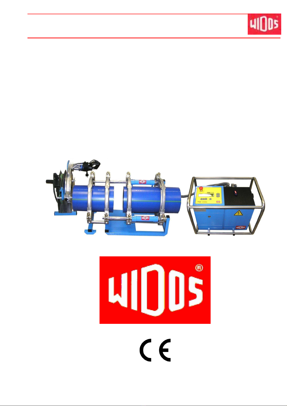
The WIDOS 4900 CNC 3.5 has been designed only for heating element butt welding of pipes
and fittings made out of the materials PE, PP, and PVDF with their diameter range going from
OD
min
= 90 mm up to OD
max
= 315 mm in the way as described below.
All use o this machine going beyond is not purpose oriented.
The machine is only to be used in a technically perfect condition, as well as purpose oriented,
safety- and danger-conscious in compliance with the working instructions and the relevant safety
regulations (especially the regulations for the prevention of accidents).
The described plastic welding machine may only be operated, maintained and repaired by
persons who are trained and informed about the dangers.
The manufacturer is not responsible for any damages caused by inexpert handling or operation.
For personal injuries, material and immaterial damages resulting herefrom, only the user is
responsible!
The control unit is reliable in the use when it is used according to the prescriptions in connection
with a welding machine designed by IDOS.
Also part of the purpose oriented use is
• respecting all the indications of the working instructions and
• performing the inspection and maintenance works.
1.2. Sa ety measures
In case of wrong use, wrong operation or wrong maintenance, the machine itself or products
standing nearby can be damaged or destroyed.
Persons being in the endangered area may be injured.
Therefore these working instructions have to be thoroughly read and the corresponding safety
regulations must be necessarily adhered to.
1.3. Con ormity
The machine corresponds in its construction to the valid recommendations of the European
Community as well as to the according European standard specifications.
The development, manufacturing and mounting of the machine were made very carefully.

Ku nst sto ffschwei ßtec hni k
Description of the product Chapter 1
02.08.2011 orking Instructions IDOS 4900 CNC 3.5 Page 7 of 68
1.4. Machine overview
No. Denomination
1 Basic machine
2 Heating element
3 Planer
4 Reception box
5 Control unit
1.5. Structure o the CNC 3.5 control unit
No. Denomination
6 Display
7 Operating field
8 SD-card
1.6. Designation o the product
The product is designated by type labels.
The type labels are attached at the control unit, at the heating element, at the planer and at the
basic machine.
They contain the type, the serial number and the year of construction of the machine.
1
3
4
5
2
6
8
7

Ku nst sto ffschwei ßtec hni k
Description of the product Chapter 1
02.08.2011 orking Instructions IDOS 4900 CNC 3.5 Page 8 of 68
1.6.1. Technical data
All important technical data of each single component are listed. This allows a quick information
about working capacity and structure.
1.6.1.1. WIDOS CNC 3.5 general data
eight (without transport box):
Dimensions (l x w x h):
40.5 kg
appr. 630x430x510 (mm)
Power: 370 att
Voltage: 230 V (± 10%)
Current: 3,0 A
Frequency: 50 Hz
Phase shift: ca. 18°
Control voltage: 5 V
Insulation system: IP 44
Hydraulic oil tank: appr. 1 l
Power emergency set: 5.5 kVA / 230 V/1~
Electro motor and pump:
Driving speed (t/min): 1340
Max. working pressure of the pump: 120 bar
orking pressure: 100 bar
Volume flow: 1.9 l/min.
1.6.1.2. Basic frame
Material of frame: Construction steel
Material of clamping devices: Aluminium
eight: 48 kg
Ø of cylinder / Ø of piston rod: 40 / 35 mm
Stroke length of cylinder: 175 mm
Max. force: (F=P*A) 5890 N (at 100 bar)
Velocity of piston rod: 5,4 cm/s
1.6.1.3. Heating element
Power: 2.5 k
Voltage: 230V (± 10 %)
Current: 10.8 A
Frequency: 50 Hz
Outside-Ø: 320 mm
Surface: nonstick-coated
Attached elements: - Control lamps
- Cable with multiple pole plug
eight: appr. 6 kg

Ku nst sto ffschwei ßtec hni k
Description of the product Chapter 1
02.08.2011 orking Instructions IDOS 4900 CNC 3.5 Page 9 of 68
1.6.1.4. Planer
Engine: Monophase-alternating current motor
Power: 1050 att
Voltage: 230 V (± 10 %)
Current: 3.8 A
Frequency: 50 Hz (± 10 %)
Driving speed n2 of the planer appr. 60
eight: appr. 14 kg
1.6.1.5. Automatic heating element (optional)
Power: 2.1 K
Voltage: 230 V (± 10 %)
Current: 9.1 A (± 10 %)
Frequency: 50 Hz
Outside-∅: 320 mm
Surface: nonstick-coated
Attached elements: - Control lamps
- Cable with multiple pole plug
eight: appr. 17 kg
1.6.1.6. Reception box for automatic heating element (optional)
eight: appr. 6 kg
See spare parts list (chapter 10) or order numbers and single parts
1.7. Equipment and accessories
Following accessories are part of the delivery:
1 x - Key for front plate / hydraulic system
1 x - SD-card (64 MB memory capacity)
Following optional accessories are available on request:
- Program ICON for reading out the data (possibility of displaying included in SD-card)
- Automatic heating element

Ku nst sto ffschwei ßtec hni k
WIDOS Einsteinstr. 5 Phone +49 (0) 71 52 99 39 - 0
. Dommer Söhne GmbH D-71254 Ditzingen-Heimerdingen Fax +49 (0) 71 52 99 39 - 40
ebsite: www.widos.de Email: info@widos.de
02.08.2011 orking Instructions IDOS 4900 CNC 3.5 Page 10 of 68
2. Sa ety rules
The base for the safe handling and the fault-free operation of this machine is the knowledge of
the basic safety indications and rules.
• These working instructions contain the most important indications to run the machine safely.
• The safety indications are to be followed by all persons working on the machine.
2.1. Explanation o the symbols and indications
In the working instructions, following denominations and signs are used for dangers:
This symbol means a possibly danger for the life and the health of persons.
The disrespect of these indications may have heavy consequences for the
health.
This symbol means a possible dangerous situation.
• The disrespect of these indications may cause slight injuries or damages on
goods.
This symbol means a possible dangerous situation by moving parts of the
machine
• The disrespect of these indications may cause heavy crushings of parts of the
body resp. damages of parts of the machine.
This symbol means a possible dangerous situation due to hot surfaces.
• The disrespect of these indications may conduct to heavy burns, respectively
to self-ignition or even fire.
This symbol gives important indications for the proper use of the machine.
• The disrespect of these indications may conduct to malfunctions and
damages on the machine or on goods in the surrounding.
Under this symbol you get user tips and particularly useful information.
• It is a help for using all the functions on your machine in an optimal way and
helps you to make the job easier.
T h e r e g u l a t i o n s o r t h e p r e v e n t i o n o a c c i d e n t s a r e v a l i d ( U V V ) .

Ku nst sto ffschwei ßtec hni k
Safety rules Chapter 2
02.08.2011 orking Instructions IDOS 4900 CNC 3.5 Page 11 of 68
2.2. Obligations o the owner
The owner is obliged only to let persons work at the machine, who
• know about basic safety and accident prevention rules and are instructed in the handling of
the machine, as well as who
• have read and understood the safety chapter of this manual and certify this by their signature.
The safety-conscious working of the staff has to be checked in regular intervals.
2.3. Obligations o the worker
All persons who are to work at the machine are obliged before working:
• to follow the basic safety and accident protection rules.
• to have read and understood the safety chapter and the warnings in this manual and to
confirm by their signature that they have well understood them.
• to inform themselves about the functions of the machine before using it.
2.4. Measures o organisation
• All equipment required for personal safety is to be provided by the owner.
• All available safety equipment is to be inspected regularly.
2.5. In ormation about sa ety precautions
• The working instructions have to be permanently kept at the place of use of the machine.
They are to be at the operator's disposal at any time and without effort.
• In addition to the manual, the common valid and the local accident protection rules and
regulations for the environmental protection must be available and followed.
• All safety and danger indications on the machine have to be in a clear readable condition.
• Every time the machine changes hands or is being rent to third persons, the working
instructions are to be sent along with and their importance is to be emphasized.
2.6. Instructions or the sta
• It must be clearly defined who is responsible for transport, mounting and dismounting, starting
the operation, setting and tooling, operation, maintenance and inspection, repair and
dismounting.
• Only skilled and trained persons are allowed to work at the machine.
• A person who is being trained may only work at the machine under supervision of an
experienced person.

Ku nst sto ffschwei ßtec hni k
Safety rules Chapter 2
02.08.2011 orking Instructions IDOS 4900 CNC 3.5 Page 12 of 68
2.7. Dangers while handling the machine
The heating element butt welding machine WIDOS 4900 CNC 3.5 is constructed according to
the latest technical standard and the acknowledged technical safety rules.
However, dangers for the operator or other persons standing nearby may occur. Also material
damages are possible.
The machine should only be used
• According to the purpose oriented usage
• In safety technical impeccable status
Disturbances, which may affect the safety of the machine must be cleared immediately.
Only skilled persons are allowed to work at electrical appliances.
• The electrical equipment of the machine has to be checked regularly.
Loose connections and damaged cables have to be replaced immediately.
• All electric tools (heating element, planer, basic machine with clamps and control unit) have to
be protected from rain and dropping water (if need be use a welding tent).
• According to VDE 0100, the use on construction sites is only allowed with a power distributor
with a FI-safety switch.
• Replace damaged front foil at the control unit in order to avoid water coming in.
System parts and pressure hoses should be made pressureless before beginning
of any repair works.
There is a danger of injuring the eyes by hydraulic oil squirting out. The hydraulic
oil can be hot!
• Damaged hydraulic hoses have to be immediately replaced.
• Make a visual inspection of the hydraulic hoses before each work beginning.
• The hydraulic oil is inedible !
• The hydraulic oil has to be handled and disposed of properly.
2.8. Speci ic dangers
2.8.1. Danger o stumbling over hydraulic and electric wires
Make sure that nobody has to step over the cables.
Make sure that the cables lay in such a way that the danger is maintained in a
minimum. Do not squeeze, buckle, etc. the cables. Avoid the hydraulic cables from
being heated up (increase of pressure!).

Ku nst sto ffschwei ßtec hni k
Safety rules Chapter 2
02.08.2011 orking Instructions IDOS 4900 CNC 3.5 Page 13 of 68
2.8.2. Danger o catching clothes by the planer
You can cut yourself or even get bones broken!
For some machines the planer may shortly turn when switching the machine on!
• Only wear clothes tight to the body.
• Do not wear rings or jewellery during the work.
• If necessary wear a hair-net.
• Always put the planer back into the reception box after and before each use.
• Only transport the planer at the handle. Do not touch the surfaces.
2.8.3. Danger o being burnt by heating element and welding area
You can burn parts of your body and inflammable materials can also be ignited!
The heating element is heated up to more than 200°C !
• Do not touch the surfaces of the heating element.
• Do not leave the heating element unsupervised.
• Take enough safety distance to inflammable materials.
• Do wear safety gloves.
• Always put the heating element back into the reception box after and before each use.
• Only transport the heating element at the handle.
2.8.4. Danger o squeezing by clamping devices and guideways
There is a danger of serious injuries: on the one hand between the inner clamping
devices and on the other hand between the outer clamping device and the end of
the guideway.
• Do not stand or put hands between clamped pipe ends.
• Do not stand or put hands between the inner clamping tools with not yet clamped pipes.
• Do not block opening and closing of the machine sledge.
2.9. Structural modi ications on the machine
• No modifications, extensions or reconstructions may be made on the machine without
permission of the manufacturer. In cases of non-compliance, any guarantee and liability
demands shall expire (see chapter 2.5).
• Machine parts which are not in a perfect condition are to be replaced immediately.
• Only use original WIDOS spare and wear parts.
• In case of purchase orders please always state the machine and version number !

Ku nst sto ffschwei ßtec hni k
Safety rules Chapter 2
02.08.2011 orking Instructions IDOS 4900 CNC 3.5 Page 14 of 68
2.10. Warranty and liability
Fundamentally our "General Sales and Delivery Conditions" are valid.
They are at the owner's disposal latest when signing the contract.
Guarantee and liability demands referring to personal injuries or damages on objects are
excluded if they are caused by one or several of the following reasons:
• not using the machine according to the prescriptions
• inexpert building-up, starting, operating, maintenance and transport of the machine
• running the machine with defective or not orderly mounted safety appliances
• ignoring the information given in this manual
• structural modifications on the machine without permission
• unsatisfactory checking of parts of the machine, which are worn out
• repairs performed in an inexpert way
• In case of catastrophes and force majeure

Ku nst sto ffschwei ßtec hni k
WIDOS Einsteinstr. 5 Phone +49 (0) 71 52 99 39 - 0
. Dommer Söhne GmbH D-71254 Ditzingen-Heimerdingen Fax +49 (0) 71 52 99 39 - 40
ebsite: www.widos.de Email: info@widos.de
02.08.2011 orking Instructions IDOS 4900 CNC 3.5 Page 15 of 68
3. Functional description
The IDOS CNC 3.5 control unit performs a butt welding process with the plastic welding
machine IDOS 4900 after entering the type of material, the pipe diameter and the pipe wall
thickness.
The welding processes are recorded and can be saved on a SD-card.
The corresponding pipe data are entered manually over the operating field.
Welding with the IDOS 4900 CNC 3.5 works as following:
The plastic pipes are clamped by means of the clamping devices (basic machine) and the pipe
ends are cut plane and parallel by means of the planer.
As soon as the pipes are plane and parallel and the misalignment smaller than 0.1 X pipe wall
thickness you can start welding.
The heating element has to be cleaned and checked before insertion and the desired
temperature prescribed by the DVS must have been reached.
The clamped pipes drive under pressure in direction of the heating element and are heated up
under the defined adjustment pressure (adjusting), the duration of the adjustment is called
adjusting time.
During the adjustment, the bead prescribed by the DVS is performed.
After reaching the prescribed bead height, the control unit automatically switches into the
heating time.
During the heating time, the basic machine is in a pressureless state and the pipe ends are
heated.
After expiration of the heating time, the sledges move apart and the heating element should be
removed as fast as possible.
The time period between the removal of the heating element and the closing of the pipes is called
change over time.
After the maximum time prescribed by the DVS, the pipe ends are driven together and a
continuous welding pressure is built up.
The pipe then cools down under the prescribed welding pressure (cooling time).
After completion of the cooling time, the pressure on the pipe is automatically released and the
welded pipe can be unclamped.
The welding process is completed.
Heating element heats the pipes
up to welding temperature
Finished welded joint with
internal and external bead

Ku nst sto ffschwei ßtec hni k
WIDOS Einsteinstr. 5 Phone +49 (0) 71 52 99 39 - 0
. Dommer Söhne GmbH D-71254 Ditzingen-Heimerdingen Fax +49 (0) 71 52 99 39 - 40
ebsite: www.widos.de Email: info@widos.de
02.08.2011 orking Instructions IDOS 4900 CNC 3.5 Page 16 of 68
4. Operating and indicating elements
4.1. Elements on the CNC 3.5 control unit
No. Name
1 Operation field with display
2 Reading unit for SD - card
3 Main switch
4 Outside temperature sensor
5 Plug box (fuse protection 1 A)
6 Mains connection cable for the control unit
7 EMERGENCY-Stop push button
8 Plug box with safety stirrup for heating element
9 Connection for the travel sensor
10 Plug for planer
11 Connections for hydraulic hoses
1
2
3
4
5
6
7
10
8
9
11

Ku nst sto ffschwei ßtec hni k
Operating and indicating elements Chapter 4
02.08.2011 orking Instructions IDOS 4900 CNC 3.5 Page 17 of 68
4.2. EMERGENCY-stop push button
There is an EMERGENCY-Stop push button (see chapter 4.1 No. 9) on the CNC control unit, for
interrupting the working process if the work piece, tools or persons are endangered by the
working pressure.
The devices connected to the plug boxes (e.g. heating element and planer ) are
not disconnected from the main power by the EMERGENCY-Stop and for this
reason dangers due to these devices are still possible.
Turn the main switch off or unplug the main connector!
• The EMERGENCY-Stop push button snaps when it is operated.
• In case the EMERGENCY-Stop push button was pushed, the system is pressure-less and the
sledge can only be moved manually.
• After elimination of the danger, the EMERGENCY-Stop push button must be unlocked again
by turning it in clockwise direction and the functions of buttons <+> and <-> (open and close
the sledge) are possible again.
4.3. Separating device or heating element
There is a tear-off bar mounted between the
movable and the fixed clamping shells on the
basic machine. It prevents the heating element
from sticking to the heated-up pipe ends.
hen inserting the heating element take care
that it lies in the zone of the throat of the tear-
off bar (see arrow).

Ku nst sto ffschwei ßtec hni k
Operating and indicating elements Chapter 4
02.08.2011 orking Instructions IDOS 4900 CNC 3.5 Page 18 of 68
4.4. Elements on heating element and planer
Denomination Function
Control lamp green
(Heating element)
There are 3 different states:
• lightening, only interrupted by short switch-off pulses: the heating
element is being heated up, the desired temperature is not yet
reached. The desired and the actual temperature are displayed
alternating on the display of the control.
• blinking: the temperature of the heating element is maintained by a
pulse-position ratio.
• o : the desired temperature has been exceeded, the heating element
is cooled automatically onto desired temperature, or the heating
element is switched off.
Safety micro switch
(Planer)
- The planer starts only when the safety micro switch is pressed.
- Locking device of the planer
On/off-switch
(Planer)
- During the planing process, the planer has to be switched on at the
switch and its corresponding lock button. The planing process is
operated by the CNC control.
Safety micro switch
On/off-switch
+ lock button
Control lamp
green

Ku nst sto ffschwei ßtec hni k
WIDOS Einsteinstr. 5 Phone +49 (0) 71 52 99 39 - 0
. Dommer Söhne GmbH D-71254 Ditzingen-Heimerdingen Fax +49 (0) 71 52 99 39 - 40
ebsite: www.widos.de Email: info@widos.de
02.08.2011 orking Instructions IDOS 4900 CNC 3.5 Page 19 of 68
5. Starting and operating
The instructions of this chapter are supposed to initiate in the operation of the machine and lead
during the appropriate starting of the machine.
This includes
• the safe operation of the machine
• using all the possible options of the machine
• economic operation of the machine
5.1. Sa ety indications
• The machine should only be operated by initiated and authorized persons.
For the qualification, a plastic welding exam can be taken according to DVS and DVG .
• In situations of danger for persons and the machine, the EMERGENCY-Stop push button or
the main switch have to be activated immediately.
• After completion of the welding work and during breaks, the machine has to be switched off.
Further be sure that no unauthorized person has access.
• According to VDE 0100, the use on construction sites is only allowed with a power distributor
with a FI-safety switch.
Check the oil level of the hydraulic system before each starting of the control unit
in order to avoid damages on the pump.
If necessary, add hydraulic oil of the quality HLPD 32.
The heating element surfaces should be clean, especially non greasy, therefore
they need to be cleaned shortly before each welding or in case of dirtiness by
means of a ibre- ree paper and cleaning agent (e.g. technical pure alcool or
cleaning tissues which are available at the IDOS company).
The anti-adhesive coating of the heating element must remain undamaged in the
working area.
Take care that all hydraulic and electric connections are connected.
Never lift or transport the basic machine
at path measuring system!
• Take into account the surrounding conditions:
The welding may not be performed under direct sun rays influence, use a welding umbrella if
necessary.
• If the surrounding temperature is under 5° C, measures have to be taken:
Use a welding tent or preheat the pipe ends if necessary.
Path measuring system

Ku nst sto ffschwei ßtec hni k
Starting and operating Chapter 5
02.08.2011 orking Instructions IDOS 4900 CNC 3.5 Page 20 of 68
5.2. Replacing the reduction inserts
• Unscrew the mounted reduction inserts.
• Screw the reduction inserts with the corresponding diameter into the clamping devices.
• If necessary (e.g. for T- pieces) the outer fixed clamping device can be dismantled by
unscrewing the three hexagon socket screws.
Dismantling of the outer fixed clamping device
5.2.1. Using small and large reduction inserts
Small reduction inserts:
• Pipe fittings often have only a short straight surface area on which they can be clamped.
• Fittings mostly need to be clamped in the inner clamping devices with the small reduction
inserts.
• hen fittings are to be welded (bends, T-pieces etc.), the inner small reduction insert can
also be used flush to the inside or to the outside.
R
Small reduction insert,
centered (for pipes)
Shown here:
Small reduction insert,
flush to the inside
(for bends, T-pieces)
Table of contents
Other widos Welding Accessories manuals
Popular Welding Accessories manuals by other brands

Miller Electric
Miller Electric 301239 owner's manual

Lincoln Electric
Lincoln Electric IM10147 Operator's manual

ESAB
ESAB MT-400EHD Instructions for use

Lincoln Electric
Lincoln Electric LN-742 Brochure & specs

Lincoln Electric
Lincoln Electric K963-3 operating instructions

Miller Electric
Miller Electric OM-2241 owner's manual