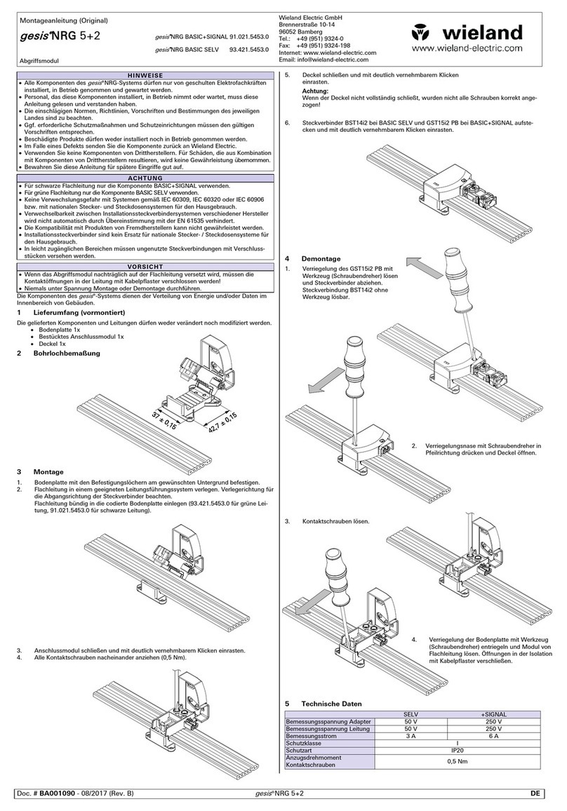
Wieland podis MOT FP C User manual

podis®
MOT FP C 2I2IO/RS 485 SEW
(Ref.-No. 83.252.xxyy.2)
podis®
MOT FP CM 2I2IO/RS 485 SEW
(Ref.-No. 83.252.xxyy.4)
podis®
MOT FP CP 2I2IO/RS 485 SEW
(Ref.-No. 83.252.0005.2)
Decentralized PROFIBUS field distributors
Operation manual
Doc. No. BA000349
Revision A
© 2007 Wieland Electric GmbH


1.1
Wieland Electric | BA000349 | 05.2007
1 | General Information
Dear customer,
Congratulations on your new components of the podis decentral automation system. You are
the owner of a PROFIBUS-DP technology product. It allows for the control of drives in indus-
trial systems.
Please familiarize yourself with this documentation. It contains all the information and help
required for proper operation of your podis system. If you still have questions or require any
help, our experts are gladly at your disposal using the contact options listed below.
Hotline Technical Service (technical questions about accessories, operating principle, product
features and application options of the podis energy bus system):
Ph.: +49 (0)9 51 / 93 24-9 98
Hotline Sales (availability, delivery time, and prices):
Ph.: +49 (0)9 51 / 93 24-9 90
Fax: +49 (0)9 51 / 93 24-9 64

1.2 Wieland Electric | BA000349 | 05.2007
General Information | 1
1.1 Version management
Document BA000349
Version Date Author
First Edition (Rev. A) 15.05.2007 T. Kluck
1.2 Additional documents
Wieland Electric provides the following documents for the podis®system:
• podis®CON
The following documents are provided by suppliers:
• MOVIMOT®MM03C-MM3XC operating instructions from SEW-Eurodrive
• MOVIMOT®MM03B-MM30B operating instructions from SEW-Eurodrive
• PROFIBUS-DP master operating instructions
All trademarks listed in this documentation and any trademarks copyrighted by third-parties
are unrestrictedly subject to the respective legal provisions and the rights of ownership of the
respective registered owners.
The simple mentioning by itself does not imply that the trademark is not protected by the
rights of others!
Documents from
Wieland Electric
Documents from
Wieland Electric
Documents from
suppliers
Documents from
suppliers
Trademarks usedTrademarks used

1.3
Wieland Electric | BA000349 | 05.2007
1|General Information
1 General Information ..................................................................................... 1.1
1.1 Version management .............................................................................1.2
1.2 Additional documents ............................................................................1.2
Documents from Wieland Electric...................................................1.2
Documents from suppliers..............................................................1.2
Trademarks used .............................................................................1.2
1.3 Table of contents....................................................................................1.3
1.4 About these operating instructions........................................................1.5
Content of these operating instructions..........................................1.5
Intended users of these operating instructions...............................1.5
Safety information ...........................................................................1.5
1.5 Intended use..........................................................................................1.6
Selection of personnel and qualifications ........................................1.7
Obvious misuse...............................................................................1.7
1.6 Project planning, programming, installation,
commissioning, and operation ...............................................................1.7
1.7 Maintenance and servicing ....................................................................1.8
1.8 Prevention of property damages and bodily injury.................................1.8
1.9 Dangers from electrical energy..............................................................1.8
2 podis®MOT FP C/CM/CP 2I2IO/RS485 SEW Device Description ..............2.1
2.1 Variant overview....................................................................................2.1
2.2 General .................................................................................................2.1
2.3 Mechanical design / housing ................................................................2.2
2.4 Connections..........................................................................................2.2
Connections at podis®MOT FP C 2I2IO/RS485 SEW .....................2.2
Connections at podis®MOT FP CM 2I2IO/RS485 SEW..................2.3
Connections at podis®MOT FP CP 2I2IO/RS485 SEW ...................2.3
PROFIBUS interface ....................................................................... 2.4
Connections for sensor cables .......................................................2.4
2.5 Controls ................................................................................................2.5
PROFIBUS-DP addressing.............................................................. 2.5
2.6 Display elements..................................................................................2.5
Status LEDs....................................................................................2.5
2.7 Technical Information ............................................................................2.6
Installation dimensions of FP C 2I2IO/RS485 SEW........................ 2.6
Installation dimensions of FP CM 2I2IO/RS485 SEW ....................2.7
Installation dimensions of FP CP 2I2IO/RS485 SEW...................... 2.8
Block diagram of FP C 2I2IO/RS485 SEW......................................2.9
Block diagram of FP CM 2I2IO/RS485 SEW................................. 2.10
Block diagram of FP CP 2I2IO/RS485 SEW.................................. 2.11
3 Mechanical Installation (Assembly)............................................................3.1
3.1 Prerequisites.........................................................................................3.1
3.1 Installation on substructure ..................................................................3.1
4 Electrical Installation .................................................................................... 4.1
General safety notes ......................................................................4.1
4.1 Connection to the podis®energy bus...................................................4.1
Procedure .......................................................................................4.3
4.2 Connection of sensor cables ................................................................ 4.4
4.3 Connection of PROFIBUS cables .........................................................4.5

1.4 Wieland Electric | BA000349 | 05.2007
General Information | 1
4.4 MOVIMOT®connection ........................................................................ 4.6
Cable ends......................................................................................4.6
Connector assignment of HAN modular insert............................... 4.6
Connector assignment of recos FLEX insert..................................4.7
Connector assignment of revos MOT.............................................4.8
Connection of open cable end........................................................4.8
5 Commissioning............................................................................................. 5.1
GSD file ..........................................................................................5.1
5.1 Selection of the installation menu .......................................................5.1
5.2 Selection of the GSD files ....................................................................5.2
5.3 Copying the image files........................................................................ 5.2
5.4 Updating the hardware catalog.............................................................5.2
5.5 Inserting a new hardware configuration (if needed) ............................. 5.3
Selecting the hardware catalog ......................................................5.3
Selecting the mounting rail and power supply................................5.3
Selecting the CPU ..........................................................................5.3
5.6 Inserting the DP slave in the PROFIBUS network................................5.5
5.7 Parameter setting of podis®MOT properties.........................................5.7
“General” tab ................................................................................. 5.7
“Parameter Setting” tab.................................................................5.8
Hex parameter setting.................................................................... 5.8
5.8 Preparing the MOVIMOT®.................................................................... 5.9
5.9 Addressing the field distributor.............................................................5.9
PROFIBUS address setting.............................................................5.9
Procedure .......................................................................................5.9
5.10 Assignment of inputs and outputs in process image........................ 5.10
5.11 PROFIBUS functions......................................................................... 5.10
DP configuration........................................................................... 5.10
5.12 Commissioning the field distributor.................................................. 5.11
6 Operation.......................................................................................................6.1
6.1 Functional check ...................................................................................6.1
Operating state...............................................................................6.1
7 Diagnostics (and Fault Removal)..................................................................7.1
7.1 Fault removal..........................................................................................7.1
7.2 Central diagnostics via PROFIBUS-DP ...................................................7.2
Error response to RS485 interruption..............................................7.2
Error response to missing or faulty supply voltage .........................7.2
PROFIBUS-DP slave diagnostics data .............................................7.3
Switching alarms on and off ............................................................7.3
7.3 Replacing the electronics module ..........................................................7.4
8 MOVILINK®Device Profile............................................................................8.1
8.1 Coding of process data.........................................................................8.1
8.2 Process output data..............................................................................8.2
8.3 Process input data................................................................................ 8.5
8.4 Program example..................................................................................8.6
9 Appendix........................................................................................................9.1
9.1 Technical data........................................................................................9.1
9.2 Ordering information ............................................................................9.2
Order number key...........................................................................9.2
Ordering information ......................................................................9.3

1.5
Wieland Electric | BA000349 | 05.2007
1|General Information
1.4 About these operating instructions
These operating instructions provide support for the installation, commissioning, and mainte-
nance of the podisMOT FP C/CM/CP 2I2IO/RS485 SEW.
It contains instructions for programming, configuring, and parameterizing the field distributor.
These operating instructions contain the information required for the as-intended use of the
product described herein
podis systems may be installed only by qualified personnel while adhering to the respective
regulations of the VDE (Association of German Electricians). For this reason, these operating
instructions are intended for technically qualified personnel (e.g. skilled persons, electrical
engineers) who is either
• familiar with the safety concepts of automation technology as project planning and pro-
gramming personnel, or
• trained in handling equipment of automation technology as operating personnel and famil-
iar with the contents of these instructions pertaining to the operation, or
• trained as installation, commissioning, and maintenance personnel which enables them
to perform operations on equipment of automation technology and who is authorized to
commission, ground, and identify electrical circuits and devices or systems according to
the standards of safety engineering.
Special requirements are:
• Basic knowledge of PROFIBUS-DP technology
• Basic knowledge of decentral drive systems
These operating instructions use different safety instructions depending upon the hazard poten-
tial:
DANGER
"Danger" identifies a direct dangerous situation or a direct dangerous condition which,
if not avoided, causes serious injuries or death. The use of this sign is restricted to
extreme situations.
WARNING
"Warning" identifies a potentially dangerous situation or a potentially dangerous conditi-
on which, if not avoided, may cause serious injuries or death.
CAUTION
"Caution" identifies a potentially dangerous situation or a potentially dangerous conditi-
on which, if not avoided, may cause minor or non-serious injuries or death. "Caution" is
also used to warn about unsafe handling or obvious misuse. "Caution" is also used for
situations in which property damage or personal injuries may occur.
Content of
these operating
instructions
Content of
these operating
instructions
Safety informa-
tion
Safety informa-
tion
Intended users
of these operat-
ing instructions

1.6 Wieland Electric | BA000349 | 05.2007
General Information | 1
NOTE
"Notice" identifies information that is directly or indirectly related to the safety of per-
sonnel or property. It is not used for dangers or dangerous situations.
"Danger" or "warning" generally refers to a risk to life or limb. In this case, property damages are
considered only if there is also a risk to bodily injury corresponding to the danger level.
1.5 Intended use
The field distributors podisMOT FP C 2I2IO/RS485 SEW, podisMOT FP CM 2I2IO/RS485 SEW
and podisMOT FP CP 2I2IO/RS485 SEW are PROFIBUS-DP actuator/sensor module on the
podis energy bus for the control and energy supply of SEW MOVIMOT AC motors with inte-
grated frequency inverter and serial communication (RS485)
The energy bus systems feature a state-of-the-art design and follow approved safety regula-
tions. Nevertheless, their use may create dangers to life and limb of users or third parties or
impairments of machinery, systems or other tangible assets.
The energy bus systems may be used only in a technically flawless condition and for proper,
safety-conscious and risk-conscious use while observing the operating instructions.The flaw-
less and safe operation of the controller assumes proper transport, proper storage and assem-
bly as well as careful operation and maintenance. In particular, malfunctions that could impair
the safety must be removed immediately.
For the intended use of the energy bus systems, the instructions described in these operat-
ing instructions for the mechanical and electrical assembly, commissioning and operation must
be observed.
Never install or commission damaged products. Damages should be filed immediately with
the transport company.
Before applying supply voltage to the field distributor, the top part (electronics cover) must
be installed and fastened onto the bottom part.
Before removing the top part (electronics cover), the energy bus segment must be de-
energized. Dangerous voltages can be present up to 1 minute after disconnecting the supply
(voltage in the DC links for decentral frequency inverters or power supplies).
During operation, do not disconnect or connect any plug connections to the attached con-
sumers.
For the project planning, installation and commissioning of the energy bus systems as
part of the supply of machines and their controllers, the machine manufacturer and user must
observe the safety regulations of machine directive 89/392/EWG and, for the specific applica-
tion case, the applicable national accident prevention regulations. Observe the applicable safety
and accident prevention regulations for the respective application cases, such as the machine
protection directive. All safety devices of the controlled machine must be implemented in such
a way that they operate independent of the controller. EMERGENCY OFF devices according to
IEC 204 (corresponding to DIN VDE 113) must remain effective in all operating modes of the
system. In an EMERGENCY OFF case, the supply voltages of all switching elements controlled
by the controller must be switched off.

1.7
Wieland Electric | BA000349 | 05.2007
1|General Information
The field distributor is intended exclusively for automation tasks in industrial systems and
machines. Any other or additional use beyond that is considered to be unintended use. The
manufacturer is not liable for any damages resulting from it.
For the intended use of the automation systems, the instructions described in these operat-
ing instructions for the mechanical and electrical assembly, commissioning and operation must
be observed.
All project planning, programming, installation, commissioning, operation and maintenance
work in conjunction with the podis electronics products may be performed only by trained
personnel (e.g. skilled persons, electrical engineers). The project planning and programming
personnel must be familiar with the safety concepts of automation technology.
The operating personnel must be trained in handling the controller and be familiar with the
operating instructions.The installation, commissioning and maintenance personnel must have
training that allows them to perform operations on automation systems.
Warnings about obvious misuse and unsafe handling are featured at the corresponding loca-
tions.
NOTE
The manufacturer is not liable for damages resulting from improper use.
1.6 Project planning, programming, installation, commissioning, and operation
With respect to their application, the field distributors of the podis series are generally a part
of larger systems or plants in which machines are controlled. For the project planning, installa-
tion and commissioning of the podis systems as part of the control of machines, the machine
manufacturer and user must must, therefore, observe the safety regulations of machine direc-
tive 89/392/EWG. For the specific application case, the national accident prevention regulations
apply, such as VBG 4.0.
All safety devices of the controlled machine must be implemented in such a way that they
operate independent of the controller. EMERGENCY OFF devices must remain effective in
all operating modes of the controller. In an EMERGENCY OFF case, the supply voltages of all
switching elements controlled by the controller must be switched off. A safety relay can be
used for this purpose.
Precautions must be taken that an interrupted control program can be properly started
again after voltage dips and power failures. No dangerous operating states may occur, not even
briefly. If necessary, EMERGENCY OFF must be forced. To prevent a an open circuit on the
signal side from causing undefined states in the controller, the corresponding safety measures
must be taken for the I/O coupling with respect to hardware and software. Devices of the
control technology and their controls must be installed in such a way that they are sufficiently
protected against inadvertent activation.
The automation devices must be de-energized before they are assembled or disassembled
or the design is changed.
Selection of
personnel and
qualifications
Selection of
personnel and
qualifications
Obvious misuseObvious misuse

1.8 Wieland Electric | BA000349 | 05.2007
General Information | 1
1.7 Maintenance and servicing
If the active device requires measuring or testing work, the regulations and execution instruc-
tions of accident prevention regulation VBG 4.0 must be observed. A suitable electric tool must
be used.
WARNING
Repairs involving control components may be performed only by authorized repair
locations. Unauthorized opening and tampering or improper repairs can cause physi-
cal injuries or property damages.
Before opening the device, always disconnect the connection to the supply system.
Control modules may be changed only in the de-energized state. Disassembly and
assembly must be carried out according to the mechanical equipment mounting
directives.
•
•
•
1.8 Prevention of property damages and bodily injury
The voltage values must not be less than or greater than the voltage values listed in the techni-
cal data since it may lead to malfunctions or damage to the devices.
If errors occur in the automation equipment that may cause heavy property damages or
even bodily injuries, additional external safety measures must be taken or devices must be
created that will ensure or force a defined operating state in case of an error (e.g. by means of
independent limit switches, mechanical interlocks, etc.).
1.9 Dangers from electrical energy
WARNING
Opening the housing provides access to certain parts that may carry dangerous volta-
ges.
The user must ensure that unauthorized and improper interventions are prevented.
The personnel must be thoroughly familiar with all danger sources and measures for com-
missioning and maintenance according to the information in the operating instructions.

2.1
Wieland Electric | BA000349 | 05.2007
2|podis®MOT FP C/CM/CP 2I2IO/RS485 SEW Device Description
2 podis®MOT FP C/CM/CP 2I2IO/ RS485 SEW Device
Description
2.1 Variant overview
podisMOT FP C 2I2IO
83.252.xxyy.2
podisMOT FP CM 2I2IO
83.252.xxyy.4
podisMOT FP CP 2I2IO
83.252.0005.2
revos connector interface
for connecting the field
devicesPreassembled hybrid
cable to the consumer
(drive)
same as 83.252.xxyy.2, but
with repair switch revosMOT connector inter-
face directly atpodis®field
distributor
2.2 General
The field distributors podisMOT FP C 2I2IO/RS485 SEW, podisMOT FP CM 2I2IO/RS485 SEW
and podisMOT FP CP 2I2IO/RS485 SEW are PROFIBUS-DP actuator/sensor module on the
podis energy bus for the control and energy supply of SEW MOVIMOT AC motors with inte-
grated frequency inverter and serial communication (RS485)
The communication between field distributor and MOVIMOT is carried out via a galvanically
isolated RS485 interface. MOVILINK profile from SEW is the protocol being used.
The PROFIBUS controller controls the complete data exchange with the PROFIBUS master.
The isolated RS485 interface serves as transfer medium.
The connection between field distributor and drive is implemented using a prefabricated
hybrid cable and plug connector.
Using prefabricated M12 connecting lines allows for connecting 2-wire and 3-wire sensors
to the four free inputs.The sensors are supplied from the field distributor via the PROFIBUS
interface.
Addressing the field distributor is carried out via the settings of two rotary switches.The
digital inputs are read via the M12 sockets without being processed by the operating system
and transferred to the PROFIBUS master upon request.
To display the current switching state and the status of the inputs, each channel features an
LED in the housing cover of the field distributor.
The contact to the energy bus is established via penetrating screws.

2.2 Wieland Electric | BA000349 | 05.2007
podis®MOT FP C/CM/CP 2I2IO/RS485 SEW Device Description | 2
2.3 Mechanical design / housing
Based on its mechanical design, the housing of the podisMOT FP C/CM/CP 2I2IO/RS485 SEW
is divided into an upper and a lower part.
The upper part contains the electronics for controlling the drive.
The upper part is fastened onto the lower part using four screws.
The base contains the connection technology for the podis energy bus.
The electrical connection between hood and base is implemented via a cable harness from
the base connected to a PCB pluggable connector in the hood.
2.4 Connections
6
1
5
2
4
3
Connections at the podis®MOT FP C 2I2IO/RS485 SEW
1 - - - - - - - Not assigned
2 DP-OUT (X2) PROFIBUS-DP output
3 DP-IN (X3) PROFIBUS-DP input
4 IO2 / IO3 (X4) Digital inputs/outputs
5 I0 / I1 (X5) Digital inputs
6 X1 Interface to the drive
Pluggable connection between
hood and base
Hood with installed electronics
Base with connection technology
(covered by cover plate)
podis®MOT FP C 2I2IO (opened), FP CM 2I2IO and FP CP 2I2IO similar
Connections at
the podis®MOT
FP C 2I2IO/
RS485 SEW

2.3
Wieland Electric | BA000349 | 05.2007
2|podis®MOT FP C/CM/CP 2I2IO/RS485 SEW Device Description
6
1
5
2
4
3
R
Connections at the podis®MOT FP CM 2I2IO/RS485 SEW
1 - - - - - - - Not assigned
2 DP-OUT (X2) PROFIBUS-DP output
3 DP-IN (X3) PROFIBUS-DP input
4 IO2 / IO3 (X4) Digital inputs/outputs
5 I0 / I1 (X5) Digital inputs
6 X1 Interface to the drive
R Repair switch
The podis
MOT FP CM 2I2IO/RS485 SEW also features a repair switch.
If the field distributor version features a repair switch, it is used to disconnect the voltage
supply for maintenance and repair work on the attached motor.
6
1
5
2
4
3
Connections at the podis®MOT FP CP 2I2IO/RS485 SEW
1 - - - - - - - Not assigned
2 DP-OUT (X2) PROFIBUS-DP output
3 DP-IN (X3) PROFIBUS-DP input
4 IO2 / IO3 (X4) Digital inputs/outputs
5 I0 / I1 (X5) Digital inputs
6 X1 Interface to the drive
Connections at
the podis®MOT
FP CM 2I2IO/
RS485 SEW
Connections at
the podis®MOT
FP CP 2I2IO/
RS485 SEW

2.4 Wieland Electric | BA000349 | 05.2007
podis®MOT FP C/CM/CP 2I2IO/RS485 SEW Device Description | 2
PROFIBUS socket X2 PROFIBUS connector X3
1
4
2
3
5
Pin Brief description Note
1
4
2
3
5
1 VP
2 A BUS-N
3 Data GND
4 B BUS-P
5 Shield PE
2-wire and 3-wire sensors can be connected to the podisMOT FP C/CM/CP 2I2IO/RS485 SEW
via M12 sockets X4 and X5.
Digital inputs X4 and X5
1
4
2
3
5
Pin Brief description X4 X5
1 24 V
2 Input I3 I1
3 0 V
4 Input I2 I0
5 PE
Digital outputs at X4
1
4
2
3
5
Pin Brief description X4
1 24 V
2 Output O3
3 0 V
4 Output O2
5 PE
NOTE
Each I/O channel can be operated alternatively as input or output.Therefore, address
space is reserved for both input and output in the process image. Make sure that a
channel used as input (e.g. an initiator) is not used as output channel at the same time.
In contrast, an output channel can be re-read as input, hereby enabling the SPS to
monitor the switching function.
CAUTION
No 24 V-voltage may be applied to the combination channel X4!
Otherwise, a current feed back to the supply voltage connection of the module will oc-
cur via the output circuit. As a consequence, malfunctioning can appear, or the output
circuit can be destroyed.
WARNING
Unused connections must be fitted with M12 caps to ensure enclosure IP65.
PROFIBUS
interface
PROFIBUS
interface
Connections for
sensor cables
Connections for
sensor cables

2.5
Wieland Electric | BA000349 | 05.2007
2|podis®MOT FP C/CM/CP 2I2IO/RS485 SEW Device Description
2.5 Controls
The podisMOT does not feature any controls.
Addressing is carried out via the setting of the two rotary switches in the electronics cover of
the field distributor.
NOTE
The two rotary switches adjust the PROFIBUS-DP address in the range from 1 to 126.
Address "0" is set in the delivery state. Of no address between 1 and 126 is set, the
system adopts address "126". In this case, the green "RUN" LED flashes.
2.6 Display elements
RUN
BUS Fault
SYS Fault
M fwd
M rev
Fu ok
IN 0
IN 1
IN/OUT 2
IN/OUT 3
No. Color Designation Meaning I/O bit
1 green RUN Bus is operating
2 red BUS Fault A fault on the bus
3 yellowSYS Fault Connection to the MOVIMOT
4 yellowM fwd CW rotation of motor
5 yellowM rev CCW rotation of motor
6 yellowFu ok Motor is operational
7 yellowIN 0 M12 input (X5) Bit 0
8 yellowIN 1 M12 input (x5) Bit 1
9 yellowIN/OUT 2 M12 input/output Bit 2
10 yellowIN/OUT 3 M12 input/output Bit 3
The status LEDs on the housing cover provide information about the status of the module. See
also section 7.1, "Diagnostics (and fault removal)".
PROFIBUS-DP
addressing
PROFIBUS-DP
addressing
Status LEDsStatus LEDs
PROFIBUS-DP addressing switches (rotary switches) in electronics cover
1 – Unit place (BCD)
2 – Tens digit (hex)
e.g. unit place = 5 and
tens digit = Acorresponds to
address 105 dec.

2.6 Wieland Electric | BA000349 | 05.2007
podis®MOT FP C/CM/CP 2I2IO/RS485 SEW Device Description | 2
2.7 Technical Information
132±0,2
2 x M4
48,2±0,2
59,5
23
23 23 54
168,5
67,6
79,5
30
l
73
53
56
Installation
dimensions of
podis®MOT FP
C 2I2IO/RS485
SEW

2.7
Wieland Electric | BA000349 | 05.2007
2|podis®MOT FP C/CM/CP 2I2IO/RS485 SEW Device Description
23
23 23 55
168,5
67,6
79,5
122,6
254
80
30
l
73
53
88
70,5
59,5
56
132±0,2
2 x M4
48,2±0,2
Installation
dimensions of
podis®MOT FP
CM 2I2IO/RS485
SEW

2.8 Wieland Electric | BA000349 | 05.2007
podis®MOT FP C/CM/CP 2I2IO/RS485 SEW Device Description | 2
23
23 23 55
169,5
67,6
79,5
195,7
35,5
59,5
70,2
70,5
160
132±0,2
2 x M4
48,2±0,2
Installation
Dimensions of
podis®MOT FP
CP 2I2IO/RS485
SEW

2.9
Wieland Electric | BA000349 | 05.2007
2|podis®MOT FP C/CM/CP 2I2IO/RS485 SEW Device Description
L1
L2
L3
+
PE
X0
X1
X3
X4
N
X2
PE
-24V
+24V
A1
A2
A3
B3
B4
PE(C)
PE(A)
B1
B2
xx
Marking bushing at
single lead
-
1
2
3
5
PE
4
6
5V
A
0V
B
24V
IO 3
0V
IO 2
1
2
3
4
5
1
2
3
4
5
1
2
3
4
5
RS485+
RS485-
L1
L2
L3
24V
0V
RS+
RS-
LED s
Ax Module A
Bx Module B
X0 Connection module
X1 Motor connection coupling
Schirm
L1
L2
L3
24V
0V
PE
RS+
RS-
X5
24V
I 1
0V
I 0
1
2
3
4
5
µC
Profibus
24V
5V
IN/OUT 3
IN/OUT 2
IN 1
IN 0
Slave Address
0...90...F
5V
A
0V
B
Block diagram of
podis®MOT FP
C 2I2IO/RS485
SEW

2.10 Wieland Electric | BA000349 | 05.2007
podis®MOT FP C/CM/CP 2I2IO/RS485 SEW Device Description | 2
L1
L2
L3
+
PE
X0
X1
X3
X4
N
X2
PE
-24V
+24V
A1
A2
A3
B3
B4
PE(C)
PE(A)
B1
B2
xx
Marking bushing
at single lead
-
1
2
3
5
PE
4
6
5V
A
0V
B
24V
IO 3
0V
IO 2
1
2
3
4
5
1
2
3
4
5
1
2
3
4
5
RS485+
RS485-
L1
L2
L3
24V
0V
RS+
RS-
LED s
Ax Module A
Bx Module B
X0 Connection module
X1 Motor connection coupling
Q1 Switch
Schirm
L1
L2
L3
24V
0V
PE
RS+
RS-
X5
24V
I 1
0V
I 0
1
2
3
4
5
µC
Profibus
24V
5V
IN/OUT 3
IN/OUT 2
IN 1
IN 0
Slave Address
0...90...F
5V
A
0V
B
Q1
Block diagram of
podis®MOT FP
CM 2I2IO/RS485
SEW
This manual suits for next models
2
Table of contents
Other Wieland Cables And Connectors manuals

Wieland
Wieland gesis NRG GST18i5 User manual
Wieland
Wieland PST 40i1 Quick start guide
Wieland
Wieland gesis GST18i3 User manual
Wieland
Wieland gesis RST16i User manual
Wieland
Wieland gesis Series User manual
Wieland
Wieland podis User manual
Wieland
Wieland gesis GST18 Series User manual
Wieland
Wieland gesis RST20i2 User manual
Wieland
Wieland RST 20i4 User manual

Wieland
Wieland gesis SPZ User manual


