WIKA IL-10 User manual

2146455.08 GB/D/F/E 08/2009
WIKA Alexander Wiegand SE & Co. KG
Alexander-Wiegand-Straße 30
63911 Klingenberg/Germany
Tel. (+49) 9372/132-295
Fax (+49) 9372/132-706
E-mail [email protected]
www.wika.de
Operating instructions
Betriebsanleitung
Mode d’emploi
Manual de instrucciones
IL-10
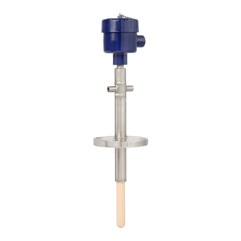
Intrinsically safe level probe /
Eigensichere Pegelsonde /
Sonde de niveau à sécurité intrinsèque /
Sonda de nivel de seguridad intrínseca
Current terms and conditions apply.
Details are available on ...
Es gelten unsere aktuellen Verkaufs-
und Lieferbedingungen siehe unter ...
Toute commande est assujettie à nos
conditions de ventes et de fournitures
dans leur dernière version en vigueur, voir
sous ...
Se aplican nuestras condiciones actuales
de venta y de suministro, que se pueden
consultar en ...
www.wika.de

2146455.08 GB/D/F/E 08/2009
2WIKA Operating instructions/Betriebsanleitung/Mode d'emploi/Instrucciones de servicio IL-10
2146455.08 GB/D/F/E 08/2009
3
WIKA Operating instructions/Betriebsanleitung/Mode d'emploi/Instrucciones de servicio IL-10
Contents Page 3-16 GB
1. Important details for your information
2. A quick overview for you
3. Signs, symbols and abbreviations
4. Function
5. For your safety
6. Packaging
7. Starting, operation
8. Maintenance, accessories
9. Trouble shooting
10. Storage, disposal
11. EC declaration of conformity
Inhalt Seite 17-30 D
1. Wichtiges zu Ihrer Information
2. Der schnelle Überblick für Sie
3. Zeichenerklärungen, Abkürzungen
4. Funktion
5. Zu Ihrer Sicherheit
6. Verpackung
7. Inbetriebnahme, Betrieb
8. Wartung, Zubehör
9. Störbeseitigung
10. Lagerung, Entsorgung
11. EG-Konformitätserklärung
Contenu Page 31-44 F
1. Informations inportantes
2. Aperçu rapide
3. Explication des symboles,abréviations
4. Fonction
5. Pour votre sécurité
6. Emballage
7. Mise en service, exploitation
8. Entretien, accessoires
9. Elimination de perturbations
10. Stockage, mise au rebut
11. Déclaration de confeamité CE
Contenido Paginás 45-58 E
1. Detalles importantes para su información
2. Resumen rápido para usted
3. Signos, símbolos y abreviaciones
4. Función
5. Para su seguridad
6. Embalaje
7. Puesta en servicio, funcionamiento
8. Mantenimiento, accesorios
9. Eliminación de perturbaciones
10. Almacenaje, eliminación de desechos
11. Declaración de conformidad CE
Contents / Inhalt / Contenu / Contenido E
F1. Important details for your information GB
Use of the product in accordance with the intended use IL-10:
Use the intrinsically safe level probe to transform the hydrostatic pressure into an electrical
signal in hazardous areas.
1. Important details for your information
Read these operating instructions before installing and starting the level probe. Keep the
operating instructions in a place that is accessible to all users at any time.
The following installation and operating instructions have been compiled by us with great care
but it is not feasible to take all possible applications into consideration. These installation and
operation instructions should meet the needs of most pressure measurement applications. If
questions remain regarding a specific application, you can obtain further information:
Via our Internet address www.wika.de / www.wika.com
The product data sheet is designated as PE 81.23
Contact WIKA for additional technical support (+49) 9372 / 132-295
If the serial number on the product label gets illegible (e.g. by mechanical damage or repain-
ting), the retraceability of the instrument is not possible any more.
WIKA level probes are carefully designed and manufactured using state-of-the-art technology.
Every component undergoes strict quality and environmental inspection before assembly and
each instrument is fully tested prior to shipment. Our environmental management system is
certified to DIN EN ISO 14001.
GB D
Certificate ATEX:
Level probe for operation in hazardous areas in compliance with the respective certificate (see
attached EC-type examination certificate DMT 00 ATEX E 045 X).
ATEX Approval ratings:
Gases and mist: Mounting to Zone 0; Installation in Zone 0, Zone 1 and Zone 2.
Dust: Mounting to Zone 20; Installation in Zone 20, Zone 21 and Zone 22.
Mining Category M1, M2.

2146455.08 GB/D/F/E 08/2009
4WIKA Operating instructions/Betriebsanleitung/Mode d'emploi/Instrucciones de servicio IL-10
2146455.08 GB/D/F/E 08/2009
5
WIKA Operating instructions/Betriebsanleitung/Mode d'emploi/Instrucciones de servicio IL-10
3. Signs, symbols and abbreviations / 4. Function GB
3. Signs, symbols and abbreviations
4. Function
2-wire Two connection lines are intended for the voltage supply.
The supply current is the measurement signal.
The hydrostatic pressure prevailing within the application is transformed into a standardised
electrical signal through the deflection of the diaphragm, which acts on the sensor element
with the power supply fed to the level probe. This electric signal changes in proportion to the
hydrostatic pressure and can be evaluated correspondingly
Potential danger of life or of
severe injuries.
Notice, important informa-
tion, malfunction.
The product complies with the
applicable European directives.
FM
Factory Mutual
The product was tested and
certified by FM Approvals. It
complies with the applicable US-
American standards on safety
(including explosion protection).
Instructions for hazardous
areas: Potential danger of
life or of severe injuries.
1. Important details for your information / 2. A quick overview for you / 3. Signs, symbols GB
Knowledge required
Install and start the level probe only if you are familiar with the relevant regulations and direc-
tives of your country and if you have the qualification required. You have to be acquainted
with the rules and regulations on hazardous areas, measurement and control technology
and electric circuits, since this level probe is „electrical equipment“ as defined by EN 50178.
Depending on the operating conditions of your application you have to have the correspon-
ding knowledge, e.g. of aggressive media.
2. A quick overview for you
If you want to get a quick overview, read Chapters 3, 5, 7 and 10. There you will get some
short safety instructions and important information on your product and its starting. Read
these chapters in any case.
Certificate FM/CSA:
Level probe for operation in hazardous areas in compliance with the respective certificate (see
Control drawing No. 2323880).
FM / CSA Approval ratings:
Intrinsically Safe with entity approval for Class I, II and III Division 1, Groups A, B, C, D, E, F, G
and Class I, Zone 0, AEx ia IIC
Dust-ignitionproof for Class II and III, Division 1, Groups E, F, and G.
Non-incendive for Class I Division 2 Groups A, B, C and D
Potential danger of life or
of severe injuries due to
catapulting parts.
Potential danger of burns
due to hot surfaces.
ATEX
European guideline for explosion
protection (Atmosphäre=AT,
Explosion=EX)
The product complies with the
requirements of the European
directive 94/9/EC (ATEX) on
explosion protection.
CSA
Canadian Standard Association
The product was tested and
certified by CSA International.
It complies with the applicable
Canadian and US-American
standards on safety (including
explosion protection).
!
Warning
Warning Warning
Caution

2146455.08 GB/D/F/E 08/2009
6WIKA Operating instructions/Betriebsanleitung/Mode d'emploi/Instrucciones de servicio IL-10
2146455.08 GB/D/F/E 08/2009
7
WIKA Operating instructions/Betriebsanleitung/Mode d'emploi/Instrucciones de servicio IL-10
5. For your safety
5. For your safety
GB
Select the appropriate level probe with regard to scale range, performance
and specific measurement conditions prior to installing and starting the
instrument.
Observe the relevant national regulations (e.g.: EN 50178, NEC, CEC) and
observe the applicable standards and directives for special applications.
If you do not observe the appropriate regulations, serious injuries and/
or damage can occur!
Please make sure that the level probe is only used within the overload threshold limit all
the time!
Observe the ambient and working conditions outlined in section 7 „Technical data”.
Ensure that the level probe is only operated in accordance with the provisions i.e. as
described in the following instructions.
Do not interfere with or change the level probe in any other way than described in these
operating instructions.
Remove the level probe from service and mark it to prevent it from being used again acci-
dentally, if it becomes damaged or unsafe for operation
Take precautions with regard to remaining media in removed level probes. Remai-
ning media in the pressure port may be hazardous or toxic!
Have repairs performed by the manufacturer only.
Information about material consistency against corrosion and diffusion can be found in our
WIKA-Handbook, 'Pressure and Temperature Measurement'.
6. Packaging / 7. Starting, operation GB
6. Packaging
Has everything been supplied?
Check the scope of supply:
Completely assembled level probes
EC-type examination certificate and Control Drawing (FM, CSA)
Inspect the level probe for possible damage during transportation. Should there be
any obvious damage, inform the transport company and WIKA without delay.
Keep the packaging, as it offers optimal protection during transportation (e.g. chan-
ging installation location, shipment for repair).
Ensure that the connection contacts will not be damaged.
7. Starting, operation
Diaphragm test for your safety
It is necessary that before starting the level probe you test the diaphragm, as this is a safety-
relevant component.
Pay attention to any liquid leaking out, for this points to a diaphragm
damage.
Use the pressure transmitter only if the diaphragm is undamaged.
Use the pressure transmitter only if it is in a faultless condition as far as the
safety-relevant features are concerned.
Consider the details given in the EC-type examination certificate as well
as the respective country specific regulations for installation and operation
in hazardous areas (e.g.: IEC 60079-14, NEC, CEC). If you do not observe
these stipulations, serious injuries and/or damage can occur.
!
Warning
!
Warning
Warning

2146455.08 GB/D/F/E 08/2009
8WIKA Operating instructions/Betriebsanleitung/Mode d'emploi/Instrucciones de servicio IL-10
2146455.08 GB/D/F/E 08/2009
9
WIKA Operating instructions/Betriebsanleitung/Mode d'emploi/Instrucciones de servicio IL-10
S #
P #
PIN assignment
Coded manufacture date
Signal
Power Supply
Product No.
Order code
Serial No.
←
(B)
→
(A)
7. Starting, operation GB
Mechanical connection Product label (example)
An additional strain relief is not necessary because the cable has a max. tensile
strength of 1000 N (500 N with FEP).
The protection cap (A) protects the secluded diaphragm (B) from damaging the
level probe during transport and immersion. Remove the protection cap if used with
viscous or contaminated media.
7. Starting, operation GB
Protect the diaphragm against any contact with abrasive substances and
pressure peaks and do not touch it with tools. If you damage the diaphragm,
no intrinsic safety can be guaranteed (ATEX, FM, CSA)!
Observe the technical data for the use of the pressure transmitter in connec-
tion with aggressive/corrosive media and for the avoidance of mechanical
hazards.
Include the screen/sheath of the connection line used as a suspension rope
in the equipotential bonding of the container.
For seperation of the zones the bulkhead cable gland in the wall must have
the ingress protection according to IEC 60 529 namely for zone 0: IP 67 and
for zone 20: IP 6X.
Integrate an overvoltage protection, if the mounting position is less than 1 m
away from the transition into Zone 0.
Installation in / mounting to zone 0 and zone 20
(In general Zone 0 is given when the pressure transmitter is surrounded by a mixture of explo-
sive gases more than 1.000 hours per year = continuous hazard).
Electrical connection
Ground the cable screen at one end, preferably in the safe, thus non-Ex,
area (EN 60079-14). For devices with flying leads, the screen is connected
to the housing. The simultaneous connection of housing and cable screen
to ground is only permitted if ground loop problems between the screen
connection (e.g. at the power supply) and housing can be excluded
(see EN 60079-14).
If the housing of the transmitter is not grounded and is likely to be subjected
to any electrostatic charging (EN 600079-14, 6.3 Paragraph 4) or if the level
probe is to be operated in Zone 0 (DMT 00 ATEX E 045 X), the cable screen
should be connected to the equipotential bonding.
Supply the level probe from an intrinsically safe current circuit (Ex ia).
Consider both the internal capacitance and inductance.
Cover flying leads with fine wires by an end splice (cable preparation).
Consider that cables for use in zones 1 and 2 must be checked with a test voltage
between conductor/earth, conductor/screen of more than 500V (AC).
Warning
Warning
Warning

2146455.08 GB/D/F/E 08/2009
10 WIKA Operating instructions/Betriebsanleitung/Mode d'emploi/Instrucciones de servicio IL-10
2146455.08 GB/D/F/E 08/2009
11
WIKA Operating instructions/Betriebsanleitung/Mode d'emploi/Instrucciones de servicio IL-10
Specifications Model IL-10
Pressure ranges bar 0.1 0.16 0.25 0.4 0.6 1
Over pressure safety bar 1 1.5 2 2 4 5
Burst pressure bar 2 2 2.4 2.4 4.8 6
Pressure ranges bar 1.6 2.5 4 6 10 16 25
Over pressure safety bar 10 10 17 35 35 35 35
Burst pressure bar 12 12 20.5 42 42 42 42
Materials
Wetted parts
Cable»PUR {FEP up to 10 bar}
Protection cap»Stainless steel {Hastelloy}
CaseStainless steel {Hastelloy}
Internal transmission fluid Synthetic oil
Power supply UBUBin VDC 10 < UB≤30
Signal output and 4 … 20 mA, 2-wire
maximum ohmic load RARAin Ohm RA ≤(UB– 10 V) / 0.02 A - (length of flying leads in m x 0.14 Ohm)
Insulation voltage Insulation complies with EN 50020, 6.4, 12
Accuracy % of span ≤0.25 {0.125} 1) (BFSL)
≤0.5 2) {0.25} 1) 2)
1) Accuracy { } for pressure ranges ≥0.25 bar
2) Including non-linearity, hysteresis, zero point and full scale error (corresponds to
error of measurement per IEC 61298-2).
Adjusted in vertical mounting position with lower pressure connection.
Non-linearity % of span ≤0.2 (BFSL) according to IEC 61298-2
Non-repeatability % of span ≤0.1
1-year stability % of span ≤0.2 (at reference conditions)
Permissible temperature of
Medium 3) 4) 5) -10 ... +60 °C -14 ... +140 °F
Load (e.g. display)
Power supply
UB+/Sig+ Positive supply / measurement connection
OV/Sig- Negative supply / measurement connection
Flying leads, conducter cross
section up
to max. 0.25 mm ²/AWG 24 with
end splices, conducter outer
diameter 7.5 mm,
IP 68 (Please note "Over pressure
safety" in Chapter 7 Specification)
brown
green
7. Starting, operation GB
Operate the level probe with a shielded cable and earth the shield at least on one
side of the cable, if the cable is longer than 30m (2-wire), or if it is run outside of the
building.
There mus be no differences in potential between medium/tank and the grounding of
the junction box and the control cabinet when the shield of the cable is applied.
Ingress protection per IEC 60529
Please make sure that the ends of cables with flying leads do not allow any ingress of
moisture.
With a line transformer you realise the mandatory galvanic isolation of the voltage
and current supply between hazardous and non-hazardous areas and ensure the
safety connection data.
Non hazardous
area
Hazardous
(classified) area
Screen/case, grey
7. Starting, operation GB
2-wire

2146455.08 GB/D/F/E 08/2009
12 WIKA Operating instructions/Betriebsanleitung/Mode d'emploi/Instrucciones de servicio IL-10
2146455.08 GB/D/F/E 08/2009
13
WIKA Operating instructions/Betriebsanleitung/Mode d'emploi/Instrucciones de servicio IL-10
Specifications Model IL-10
{-10 ... +85°C with FEP-cable} {-14 ... +185 °F with FEP-cable}
Storage 3) -10 ... +60 °C -14 ... +140 °F
3) Also complies with EN 50178, Tab. 7, Operation (C) 4K4H, Storage (D) 1K4,
Transport (E) 2K3
4) Other temperature ranges are possible, depending on the electrical connection;
see EC-type examination certificate and table page 13)
Compensated temp range 0 ... +50 °C 32 ... +122 °F
Temperature coefficients within
compensated temp range
Mean TC of zero% of span ≤0.2 / 10 K (< 0.4 for pressure range ≤250 mbar)
Mean TC of range% of span ≤0.2 / 10 K
Ex-protection ATEX Category 5) 1G (IIA), 1/2 G, 2G, 1D, 1/2D, 2D, M1, M2
Ignition protection type EEx ia I/II C T4, EEx ia I/II C T5, EEx ia I/II C T6
Ex-protection FM, CSA Class I, II and III
Ignition protection type Instrinsic safe Class I, II, III Division 1,
Group A, B, C, D, E, F, G and Class I, Zone 0 AEx ia II C
5) Read the operating conditions and safety-relevant data in the EC-type
examination certificate in any case (DMT 00 ATEX E 045 X)
CE- conformitiy
EMC directive2004/108/EEC, EN 61 326 Emission (Group 1, Class B) and Immunity
(industrial locations)
ATEX-Directive ATEX of equip-
ment intended for use in potenti-
ally explosive atmospheres
94/9/EC
Approval German Lloyd GL Environmental Category C, F, EMC 1
RF-immunity V/m 10
Burst kV 4
Wiring protection
Short-circuit proofnessSig+ towards UB-
Reverse polarity protectionUB+ towards UB-
Electrical connections Category Ambience-/ Medium tempera-
ture range
PUR-cable 1 G (IIA), 2 G (IIA), M1, 1 D, 2 D -10 ... +60 °C 14 ... +140 °F
FEP-cable 1 G (IIA) -30 ... +60 °C -22 ... +140 °F
2 G (IIA), M1 -30 ... +105 °C -22 ... +221 °F
1 D, 2 D -30 ... +80 °C -22 ... +176 °F
Specifications Model IL-10
Weight kg Approx. 0.2
Cable»kg Approx. 0.08 per m cable
7. Starting, operation GB
{ } Items in curved brackets are optional extras for additional price.
Functional test
Observe the ambient and working conditions outlined in section 7
„Technical data.
Please make sure that the level probe is only used within the over load
threshold limit at all times!
When touching the level probe, keep in mind that the surfaces of the instru-
ment components might get hot during operation.
The output signal must be proportional to the pressure. If not, this might point to a
damage of the diaphragm. In that case refer to chapter 9 „Troubleshooting“.
7. Starting, operation / 8. Maintenance, accessories GB
8. Maintenance, accessories
Accessories: For details about the accessories, please refer to WIKA‘s price list, WIKA‘s
product catalog on CD or or contact our sales department.
WIKA level probes require no maintenance.
Have repairs performed by the manufacturer only.
Permissible temperature ranges depending on electrical connections
Warning
Caution

2146455.08 GB/D/F/E 08/2009
14 WIKA Operating instructions/Betriebsanleitung/Mode d'emploi/Instrucciones de servicio IL-10
2146455.08 GB/D/F/E 08/2009
15
WIKA Operating instructions/Betriebsanleitung/Mode d'emploi/Instrucciones de servicio IL-10
Failure Possible cause Procedure
Signal span dropping off/too small
Diaphragm is damaged, e.g. through
impact, abrasive/agressive media;
corrosion of diaphragm/pressure
connector; transmission fluid missing.
Contact the manufacturer and replace
the instrument
Signal span drops off Moisture present (e.g. at the cable tail) Install the cable correctly
Signal span erratic Working temperature too high/too low Ensure permissible temperatures as per
the Operating Instructions
Signal span incorrect Working temperature too high/too low Ensure permissible temperatures as per
the Operating Instructions
Abnormal zero point signal Medium or ambient temperature too
high/too low
Control the internal temperature of the
instrument within the permissible range;
observe the allowable temperature error
(see Operating Instructions)
Diaphragm is damaged, e.g. through
impact, abrasive/agressive media;
corrosion of diaphragm/pressure
connector.
Replace instrument
Abnormal zero point signal Working temperature too high/too low Ensure permissible temperatures as per
the Operating Instructions
Zero point signal unstable/ too low/high Moisture present (e.g. at the cable tail) Install the cable correctly,
filter element insertion
Failure Possible cause Procedure
Hot instrument case surface Permissible ambient or medium tempe-
rature exceeded
Ensure permissible ambient/medium
temperature limits are observed (see
Operating Instructions)
9. Trouble shooting GB
Please verify in advance if pressure is being applied (valves/ ball valve etc. open) and if the
right voltage supply and the right type of wiring (2-wire) has been chosen?
9. Trouble shooting / 10. Storage, disposal GB
If the problem persists, contact our sales department.
USA, Canada
If the problem continues, contact WIKA or an authorized agent for assistance. If the level
probe must be returned obtain an RMA (return material authorization) number and shipping
instructions from the place of purchase. Be sure to include detailed information about the
problem. Level probes received by WIKA without a valid RMA number will not be accepted.
Process material certificate (Contamination declaration for returned goods)
Purge / clean dismounted instruments before returning them in order to protect our employees
and the environment from any hazard caused by adherent remaining media.
Service of instruments can only take place safely when a Product Return Form has been
submitted and fully filled-in. This Return Form contains information on all materials with which
the instrument has come into contact, either through installation, test purposes, or cleaning.
You can find the Product Return Form on our internet site (www.wika.de / www.wika.com).
In case of unjustified reclamation we charge the reclamation handling expenses.
*) Make sure that after the assembly the unit is working properly. In case the error continues to exist send in the instrument for
reparation (or replace the unit).
10. Storage, disposal
When storing or disposing of the level probe, take precautions with regard
to remaining media in removed level probes. We recommend cleaning the
level probe properly and carefully. Remaining media in the pressure port
may be hazardous or toxic!
Dispose of instrument components and packaging materials in accordance with the
respective waste treatment and disposal regulations of the region or country to which
the instrument is supplied.
Disposal
Mount the protection cap when storing the pressure transmitter in order to prevent any
damage to the diaphragm.
Storage
Take precautions with regard to remaining media in removed level probes.
Remaining media in the pressure port may be hazardous or toxic!
Remove the level probe from service and mark it to prevent it from being
used again accidentally, if it becomes damaged or unsafe for operation.
Have repairs performed by the manufacturer only.
Do not insert any pointed or hard objects into the pressure port for cleaning to prevent
damage to the diaphragm.
9. Trouble shooting
!
Warning
!
Warning
2146455.08 GB/D/F/E 08/2009
16 WIKA Operating instructions/Betriebsanleitung/Mode d'emploi/Instrucciones de servicio IL-10
2146455.08 GB/D/F/E 08/2009
17
WIKA Operating instructions/Betriebsanleitung/Mode d'emploi/Instrucciones de servicio IL-10
11. EC declaration of conformity GB
11. EC declaration of conformity
WIKA reserves the right to alter these technical specifications.
1. Wichtiges zu Ihrer Information D
Zulassung ATEX:
Druckmessgerät zur bestimmungsgemäßen Verwendung in explosionsgefährdeten Bereichen
(siehe beiliegende EG-Baumusterprüfbescheinigung DMT 00 ATEX E 045 X).
ATEX Zulassungseigenschaften:
für Gase und Nebel: Anbau an Zone 0; Einbau in Zone 0, Zone 1 und Zone 2
Stäube: Anbau an Zone 20; Einbau in Zone 20, Zone 21 und Zone 22
Bergbau: Kategorie M1, M2.
1. Wichtiges zu Ihrer Information
Lesen Sie diese Betriebsanleitung vor Montage und Inbetriebnahme der Pegelsonde.
Bewahren Sie die Betriebsanleitung an einem für alle Benutzer jederzeit zugänglichen Ort auf.
Die nachfolgenden Einbau- und Betriebshinweise haben wir mit Sorgfalt zusammengestellt.
Es ist jedoch nicht möglich, alle erdenklichen Anwendungsfälle zu berücksichtigen. Sollten Sie
Hinweise für Ihre spezielle Aufgabenstellung vermissen, können Sie hier weitere Informationen
finden:
Über unsere Internet-Adresse www.wika.de / www.wika.com
Die Bezeichnung des zugehörigen Datenblattes ist PE 81.23
Anwendungsberater: (+49) 9372/132-295
Wird die Seriennummer auf dem Typenschild unleserlich (z. B. durch mechanische Beschädi-
gung oder Übermalen), ist eine Rückverfolgbarkeit nicht mehr möglich.
Die in der Betriebsanleitung beschriebenen WIKA-Druckmessgeräte werden nach den
neuesten Erkenntnissen konstruiert und gefertigt. Alle Komponenten unterliegen während der
Fertigung strengen Qualitäts- und Umweltkriterien. Unser Umweltmanagementsystem ist nach
DIN EN ISO 14001 zertifiziert.
Bestimmungsgemäße Produktverwendung IL-10:
Verwenden Sie die eigensichere Pegelsonde, um in explosionsgefährdeten Bereichen hydro-
statischen Druck in ein elektrisches Signal zu wandeln.
Original see Page 59
Text

2146455.08 GB/D/F/E 08/2009
18 WIKA Operating instructions/Betriebsanleitung/Mode d'emploi/Instrucciones de servicio IL-10
2146455.08 GB/D/F/E 08/2009
19
WIKA Operating instructions/Betriebsanleitung/Mode d'emploi/Instrucciones de servicio IL-10
1. Wichiges zu Ihrer Information/ 2. Schneller Überblick / 3. Zeichenerklärungen, Abkürzungen D
Ihre erforderlichen Kenntnisse
Montieren und nehmen Sie die Pegelsonde nur in Betrieb, wenn Sie mit den zutreffenden
landesspezifischen Richtlinien vertraut sind und die entsprechende Qualifikation besitzen. Sie
müssen mit den Vorschriften und Kenntnissen für explosionsgefährdete Bereiche, Mess- und
Regeltechnik sowie elektrische Stromkreise vertraut sein, da die Pegelsonde ein „elektrisches
Betriebsmittel“ nach EN 50178 ist. Je nach Einsatzbedingung müssen Sie über entspre-
chendes Wissen verfügen, z. B. über agressive Medien.
2. Der schnelle Überblick für Sie
Wollen Sie sich einen schnellen Überblick verschaffen, lesen Sie Kapitel 3, 5, 7 und 10. Dort
erhalten Sie kurze Hinweise zu Ihrer Sicherheit und wichtige Informationen über Ihr Produkt
und zur Inbetriebnahme. Lesen Sie diese unbedingt.
Zulassung FM/CSA:
Druckmessgerät zur bestimmungsgemäßen Verwendung in explosionsgefährdeten Bereichen
(siehe Control drawing Nr. 2323880)
FM / CSA Zulassungseigenschaften:
Intrinsically Safe mit Gerätezulassung für Class I, II und III Division 1, Gruppe A, B, C, D, E, F,
G und Class I, Zone 0, AEx ia IIC.
Dust-ignitionproof für Class II und III, Division 1, Gruppe E, F und G.
Non-incendive für Class I Division 2 Gruppe A, B, C und D
3. Zeichenerklärungen, Abkürzungen
Mögliche Gefahr für Ihr
Leben oder schwerer
Verletzungen.
Ex-Hinweise:
Mögliche Gefahr für Ihr
Leben oder schwerer Verlet-
zungen.
Mögliche Gefahr für Ihr
Leben oder schwerer Verlet-
zungen durch wegschleu-
dernde Teile.
Mögliche Gefahr von
Verbrennungen durch
heisse Oberflächen.
3. Zeichenerklärungen, Abkürzungen / 4. Funktion D
2-Leiter Zwei Anschlussleitungen dienen zur Spannungsversorgung.
Der Speisestrom ist das Mess-Signal.
4. Funktion
Mittels Sensorelement und unter Zuführung von Hilfsenergie wird über die Verformung einer
Membran der anstehende hydrostatische Druck in Ihrer Anwendung in ein verstärktes standar-
disiertes elektrisches Signal umgewandelt. Dieses elektrische Signal verändert sich proporti-
onal zum hydrostatischen Druck bzw. Füllstand und kann entsprechend ausgewertet werden.
Hinweis, wichtige Information,
Funktionsstörung.
Das Produkt stimmt mit den
zutreffenden europäischen
Richtlinien überein.
FM
Factory Mutual
Das Produkt wurde von FM
Approvals geprüft und zerti-
fiziert. Es stimmt überein mit
den anwendbaren US-amerika-
nischen Normen zur Sicherheit
(einschließlich Explosionsschutz).
ATEX
Europäische Explosionsschutz-
Richtlinie (Atmosphäre=AT,
Explosion=EX)
Das Produkt stimmt überein mit
den Anforderungen der europä-
ischen Richtlinie 94/9/EG (ATEX)
zum Explosionsschutz.
CSA
Canadian Standard Association
Das Produkt wurde durch CSA
International geprüft und zertifi-
ziert. Es stimmt überein mit den
anwendbaren kanadischen und
US-amerikanischen Normen zur
Sicherheit (einschließlich Explosi-
onsschutz).
Warnung
Vorsicht
!
Warnung
Warnung

2146455.08 GB/D/F/E 08/2009
20 WIKA Operating instructions/Betriebsanleitung/Mode d'emploi/Instrucciones de servicio IL-10
2146455.08 GB/D/F/E 08/2009
21
WIKA Operating instructions/Betriebsanleitung/Mode d'emploi/Instrucciones de servicio IL-10
5. Zu Ihrer Sicherheit D
Angaben zu Korrosions- bzw. Diffusionsbeständigkeit der Gerätewerkstoffe entnehmen Sie
bitte unserem WIKA-Handbuch zur Druck- und Temperaturmesstechnik.
5. Zu Ihrer Sicherheit
Wählen Sie die richtige Pegelsonde hinsichtlich Messbereich, Ausführung
und spezifischen Messbedingungen vor Montage oder Inbetriebnahme.
Halten Sie die entsprechenden landesspezifischen Vorschriften ein (z. B.:
EN 50178, NEC, CEC) und beachten Sie bei speziellen Anwendungen
die geltenden Normen und Richtlinien. Wenn Sie die entsprechenden
Vorschriften nicht beachten, können schwere Körperverletzungen und
Sachschäden entstehen!
Betreiben Sie die Pegelsonde immer innerhalb des Überlastgrenzbereiches!
Beachten Sie die Betriebsparameter gemäß Punkt 7 „Technische Daten“.
Stellen Sie sicher, dass die Pegelsonde nur bestimmungsgemäß -also wie in der folgenden
Anleitung beschrieben- betrieben wird.
Unterlassen Sie unzulässige Eingriffe und Änderungen an der Pegelsonde, welche nicht in
dieser Betriebsanleitung beschrieben sind.
Setzen Sie die Pegelsonde außer Betrieb und schützen Sie sie gegen versehentliche Inbe-
triebnahme, wenn Sie Störungen nicht beseitigen können.
Ergreifen Sie Vorsichtsmaßnahmen für Messstoffreste in ausgebauten Pegelsonden.
Messstoffreste können zur Gefährdung von Menschen, Umwelt und Einrichtung
führen!
Lassen Sie Reparaturen nur vom Hersteller durchführen.
6. Verpackung / 7. Inbetriebnahme, Betrieb D
6. Verpackung
7. Inbetriebnahme, Betrieb
Es ist erforderlich, dass Sie vor Inbetriebnahme des Druckmessgerätes die Membran prüfen,
denn sie ist ein sicherheitsrelevantes Teil.
Überprüfen Sie den Lieferumfang:
Komplett montierte Pegelsonden
Baumusterprüfbescheinigung und Control Drawing (FM, CSA)
Untersuchen Sie die Pegelsonde auf eventuell entstandene Transportschäden. Sind
offensichtlich Schäden vorhanden, teilen Sie dies dem Transportunternehmen und
WIKA unverzüglich mit.
Bewahren Sie die Verpackung auf, denn diese bietet bei einem Transport einen opti-
malen Schutz (z. B. wechselnder Einbauort, Reparatursendung).
Achten sie darauf, dass die Anschlusskontakte nicht beschädigt werden.
Achten Sie auf auslaufende Flüssigkeit, denn sie ist ein Hinweis auf eine
Membranbeschädigung.
Setzen Sie das Druckmessgerät nur ein, wenn die Membran unbeschädigt
ist.
Setzen Sie das Druckmessgerät nur in sicherheitstechnisch einwandfreiem
Zustand ein.
Membran-Prüfung zu Ihrer Sicherheit
Wurde alles geliefert?
Beachten Sie die Angaben der geltenden Baumusterprüfbescheinigung
sowie die jeweiligen landesspezifischen Vorschriften zur Installation und
Einsatz in explosionsgefährdeten Bereichen (z.B.: IEC 60079-14, NEC,
CEC). Wenn Sie diese nicht beachten, können schwere Körperverletzungen
und Sachschäden entstehen.
Warnung
!
Warnung
!
Warnung

2146455.08 GB/D/F/E 08/2009
22 WIKA Operating instructions/Betriebsanleitung/Mode d'emploi/Instrucciones de servicio IL-10
2146455.08 GB/D/F/E 08/2009
23
WIKA Operating instructions/Betriebsanleitung/Mode d'emploi/Instrucciones de servicio IL-10
←
(B)
→
(A)
S #
P #
Anschlussbelegung
Codiertes Herstelldatum
Signal
Spannungsversorgung
Erzeugnis-Nr.
Bestellcode
Fabrik-Nr.
7. Inbetriebnahme, Betrieb D
Montage mechanischer Anschluss Typenschild (Beispiel)
Das Anschlusskabel weist eine maximale Zugkraft von 1000 N (500 N bei FEP auf, so
dass eine zusätzliche Zugentlastung entfällt!
Die Schutzkappe (A) schützt die innenliegende Membran (B) vor Beschädigung
während des Transportes und beim Absenken der Sonde. Entfernen Sie die Schutz-
kappe, wenn das Messmedium zähflüssig oder verschmutzt ist.
7. Inbetriebnahme, Betrieb D
Schützen Sie die Membran vor Kontakt mit abrasiven Medien und gegen
Schläge. Wenn Sie die Membran beschädigen, ist kein Explosionsschutz
gewährleistet (ATEX, FM, CSA)!
Beachten Sie die Technischen Daten zur Verwendung des Druckmessge-
rätes in Verbindung mit agressiven/korrosiven Medien und zur Vermeidung
von mechanischen Gefährdungen.
Beziehen Sie den Schirm der als Hängeseil verwendeten Anschlussleitung in
den Potentialausgleich des Behälters mit ein.
Die Kabeldurchführung in der Wand zur Trennung der Zonen muss einer
Schutzart nach IEC 60 529 entsprechen, und zwar für die Zone 0: IP 67, für
die Zone 20: IP 6X.
Integrieren Sie einen Überspannungsschutz bei einer Entfernung von
weniger als 1 m vom Eintritt in die Zone 0.
Ein- und Anbau an Zone 0 und Zone 20
(Zone 0 bedeutet, dass explosionsfähiges Gasgemisch >1000 Stunden pro Jahr am Druck-
messgerät vorliegt).
Montage elektrischer Anschluss
Erden Sie den Kabelschirm einseitig und bevorzugt im sicheren, also Nicht-
Ex-Bereich (EN 60079-14). Bei Geräten mit Kabelausgang ist der Schirm
mit dem Gehäuse verbunden. Der gleichzeitige Anschluss von Gehäuse
und Kabelschirm an Erde ist nur dann zulässig, wenn eine Potentialver-
schleppung zwischen Schirmanschluss (z.B. am Speisegerät) und Gehäuse
ausgeschlossen werden kann (siehe EN 60079-14).
Der Kabelschirm ist in den Potentialausgleich einzubinden, wenn das
Gehäuse des Messumformers nicht geerdet ist und elektrostatische Aufla-
dungen zu befürchten ist (EN 600079-14, 6.3 Absatz 4) oder wenn die
Pegelsonde in Zone 0 betrieben wird (DMT 00 ATEX E 045 X).
Versorgen Sie die Pegelsonde aus einem eigensicheren Stromkreis (Ex ia).
Beachten Sie die innere wirksame Kapazität und Induktivität.
Versehen Sie feindrahtige Leiterenden mit Aderendhülsen (Kabelkonfektionierung).
Beachten Sie, dass bei Kabeln für den Einsatz in Zone 1 und 2 die Prüfspannung
Leiter/Erde, Leiter/Schirm > 500V Wechselspannung betragen muss.
Warnung
Warnung
Warnung

2146455.08 GB/D/F/E 08/2009
24 WIKA Operating instructions/Betriebsanleitung/Mode d'emploi/Instrucciones de servicio IL-10
2146455.08 GB/D/F/E 08/2009
25
WIKA Operating instructions/Betriebsanleitung/Mode d'emploi/Instrucciones de servicio IL-10
Technische Daten Typ IL-10
Messbereich bar 0,1 0,16 0,25 0,4 0,6 1
Überlastgrenze bar 1 1,5 2 2 4 5
Berstdruck bar 2 2 2,4 2,4 4,8 6
Messbereich bar 1,6 2,5 4 6 10 16 25
Überlastgrenze bar 10 10 17 35 35 35 35
Berstdruck bar 12 12 20,5 42 42 42 42
Werkstoff
Messstoffberührte Teile
Kabel»PUR {FEP bis 10 bar}
Schutzkappe»CrNi-Stahl {Hastelloy}
GehäuseCrNi-Stahl {Hastelloy}
Interne Übertragungsflüssigkeit Synthetisches Öl
Hilfsenergie UBUBin VDC 10 < UB≤ 30
Ausgangssignal und zulässige 4 … 20 mA, 2-Leiter
max. ohmsche Bürde RARAin Ohm RA≤ (UB– 10 V)/0,02 A-(Länge der Kabelausführung in m x 0,14 Ohm)
Isolationsspannung Isolierung entspricht EN 50020, 6.4, 12
Genauigkeit % d. Spanne ≤0,25 {0,125} 1) (BFSL)
≤0,5 2) {0,25} 1) 2)
1) Genauigkeit { } für Messbereiche ≥0,25 bar
2) Einschließlich Nichtlinearität, Hysterese, Nullpunkt- und Endwertabweichung
(entspricht Messabweichung nach IEC 61298-2).
Kalibriert bei senkrechter Einbaulage Druckanschluss nach unten.
Nichtlinearität % d. Spanne ≤0,2 (BFSL) nach IEC 61298-2
Nichtwiederholbarkeit % d. Spanne ≤0,1
Stabilität pro Jahr % d. Spanne ≤0,2 (bei Referenzbedingungen)
Zulässige Temperaturbereiche
Messstoff 3) 4) 5) °C -10 ... +60 {-10 ... +85 mit FEP Kabel}
braun
grün
Betreiben Sie die Pegelsonde mit geschirmter Leitung und erden Sie den Schirm auf
mindestens einer Leitungsseite, wenn die Leitungen länger als 30m (2-Leiter) sind
oder das Gebäude verlassen.
Es dürfen keine Potentialunterschiede zwischen Medium/Behälter und der Massean-
bindung der Anschlussdose bzw. des Schaltschrankes herrschen, wenn der Schirm
des Kabels aufgelegt wird.
Schutzart IP nach IEC 60 529
Stellen Sie bei Kabelausgängen sicher, dass am Ende des Kabels keine Feuchtigkeit
eintritt.
7. Inbetriebnahme, Betrieb D7. Inbetriebnahme, Betrieb D
Verbraucher
Spannungsversorgung
UB+/Sig+ Positiver Versorgungs- / Messanschluss
OV/Sig- Negativer Versorgungs- / Messanschluss
Mit einem Speisetrenner realisieren Sie die zwingend nötige galvanische Trennung
der Spannungs- und Stromversorgung zwischen Ex- und Nicht-Ex-Bereich und
stellen die sicherheitstechnischen Anschlussdaten sicher.
Kabelausgang,
Leitungsquerschnitt 0,25 mm2/
AWG 24 mit Aderendhülsen,
Leitungsaußendurchmesser 7,5 mm,
IP 68 (siehe Pkt. 7 Technische Daten
"Überlastgrenze")
2-Leiter
Nicht Ex-Bereich Ex-Bereich
Schirm
(grau, auf Gehäuse
aufgelegt)

2146455.08 GB/D/F/E 08/2009
26 WIKA Operating instructions/Betriebsanleitung/Mode d'emploi/Instrucciones de servicio IL-10
2146455.08 GB/D/F/E 08/2009
27
WIKA Operating instructions/Betriebsanleitung/Mode d'emploi/Instrucciones de servicio IL-10
Technische Daten Typ IL-10
Lagerung 3) °C -10 ... +60
3) Erfüllt auch EN 50178, Tab. 7, Betrieb (C) 4K4H, Lagerung (D) 1K4,
Transport (E) 2K3
4) Weitere Temperaturbereiche in Abhängigkeit der elektrischen Anschlüsse, siehe
EG-Baumusterprüfbescheinigung und Tabelle auf Seite 27)
Kompensierter Temperaturbereich °C 0 ... +50
Temperaturkoeffizienten im
kompensierten Temperaturbereich
Mittlerer TK des Nullpunktes% d. Spanne ≤0,2 / 10 K (< 0,4 für Messbereiche ≤250 mbar)
Mittlerer TK der Spanne% d. Spanne ≤0,2 / 10 K
Ex -Schutz ATEX Kategorie 5) 1G (II A), 1/2G , 2G, 1D, 1/2D, 2D, M1, M2
Zündschutzart EEx ia I/II C T4, EEx ia I/II C T5, EEx ia I/II C T6
Ex -Schutz FM, CSA Class I, II und III
Zündschutzart Eigensicher Class I, II, III Division 1,
Group A, B, C, D, E, F, G und Class I, Zone 0 AEx ia II C
5) Lesen Sie unbedingt die Einsatzbedingungen und sicherheitstechnischen Daten
in der EG Baumusterprüfbescheinigung nach (DMT 00 ATEX E 045 X).
CE- Kennzeichen
EMV-Richtlinie2004/108/EG, EN 61326 Emission (Gruppe 1, Klasse B) und
Störfestigkeit (industrieller Bereich)
ATEX-Richtlinie für Geräte zur
bestimmungsgemäßen Verwen-
dung in explosionsgefährdeten
Bereichen
94/9/EG
Zulassung German Lloyd GL Environmental Category C, F, EMC 1
HF-Immunität V/m 10
Burst kV 4
Elektrische Schutzarten
KurzschlussfestigkeitSig+ gegen UB-
VerpolschutzUB+ gegen UB-
Technische Daten Typ IL-10
Gewicht kg Ca. 0,2
Kabel»kg Ca. 0,08 je m Kabel
Elektrischer
Anschluss Kategorie Umgebungs-/
Medientemperaturbereich
PUR-Kabel 1 G (IIA), 2 G (IIA), M1, 1 D, 2 D -10 ... +60 °C
FEP-Kabel 1 G (IIA) -30 ... +60 °C
2 G (IIA), M1 -30 ... +105 °C
1 D, 2 D -30 ... +80 °C
7. Inbetriebnahme, Betrieb D7. Inbetriebnahme, Betrieb / 8. Wartung, Zubehör D
{ } Angaben in geschweiften Klammern beschreiben gegen Mehrpreis lieferbare Sonderheiten.
Funktionsprüfung
Beachten Sie die Betriebsparameter gemäß Punkt 7„Technische Daten“.
Betreiben Sie die Pegelsonde immer innerhalb des Überlastgrenzbereichs!
Beachten Sie beim Berühren des Druckmessgerätes, dass die Oberflächen
der Gerätekomponenten während des Betriebes heiß werden können.
Das Ausgangssignal muss sich dem anstehenden Druck proportional verhalten. Wenn
dies nicht so ist, kann das ein Hinweis auf eine Beschädigung der Membran sein. Lesen
Sie in diesem Fall in Kapitel 10 „Störbeseitigung“ nach.
8. Wartung, Zubehör
Zubehör: Entnehmen Sie bitte Zubehörangaben unserer aktuellen Standardpreisliste, dem
CD-Katalog oder setzen Sie sich mit unserem Vertriebsmitarbeiter in Verbindung.
WIKA Druckmessgeräte sind wartungsfrei.
Lassen Sie Reparaturen nur vom Hersteller durchführen.
Zulässige Temperaturbereiche in Abhängigkeit des elektrischen Anschlusses
Warnung
Vorsicht

2146455.08 GB/D/F/E 08/2009
28 WIKA Operating instructions/Betriebsanleitung/Mode d'emploi/Instrucciones de servicio IL-10
2146455.08 GB/D/F/E 08/2009
29
WIKA Operating instructions/Betriebsanleitung/Mode d'emploi/Instrucciones de servicio IL-10
Störung Mögliche Ursache Maßnahme
Signalspanne fällt/ab/zu klein
Membranbeschädigung, z. B. durch
Schläge, abrasives/agressives Medium;
Korrosion an Membran/Druckan-
schluss; Übertragungsmedium fehlt
Hersteller kontaktieren und Gerät
austauschen
Signalspanne fällt ab Feuchtigkeit eingetreten (z. B. am
Kabelende) Kabel korrekt montieren
Signalspanne schwankend Zu hohe/niedrige Einsatztemperaturen Zulässige Temperaturen gemäß
Betriebsanleitung einhalten
Signalspanne ungenau Zu hohe/niedrige Einsatztemperaturen Zulässige Temperaturen gemäß
Betriebsanleitung einhalten
Abweichendes Nullpunkt-Signal Medium- bzw. Umgebungstemperatur
zu hoch/niedrig
Gerät innerhalb zulässigem Tempe-
raturbereich betreiben; zulässigen
Temperaturfehler beachten (siehe
Betriebsanleitung)
Membranbeschädigung, z. B. durch
Schläge, abrasives/agressives Medium;
Korrosion an Membran/Druckanschluss
Gerät austauschen
Zu hohe/niedrige Einsatztemperaturen Zulässige Temperaturen gemäß
Betriebsanleitung einhalten
Nullpunktsignal instabil/ zu niedrig/hoch Feuchtigkeit eingetreten (z.B. Kabe-
lende)
Kabel korrekt montieren,
Filterelement einsetzen
Störung Mögliche Ursache Maßnahme
Heiße Gehäuseoberfläche Zulässige Umgebungs-/Mediumtempe-
ratur überschritten
Zulässige Umgebungs-/Mediumtempe-
ratur einhalten (siehe Betriebsanleitung)
Kein Ausgangssignal Keine/Falsche Versorgungsspannung
oder Stromstoß
Versorgungsspannung gemäß Betriebs-
anleitung korrigieren *)
9. Störbeseitigung D
Prüfen Sie bitte vorab, ob Druck ansteht (Ventile/Kugelhahn usw. offen) und ob Sie die richtige
Spannungsversorgung und die richtige Verdrahtungsart (2-Leiter) gewählt haben.
9. Störbeseitigung / 10. Lagerung, Entsorgung D
Im unberechtigtem Reklamationsfall berechnen wir die Reklamationsbearbeitungs-Kosten.
*) Überprüfen Sie nach der Montage die korrekte Arbeitsweise des Systems.
Besteht der Fehler weiterhin, senden Sie das Gerät zur Reparatur ein (oder tauschen Sie das Gerät aus).
Wenn das Problem bestehen bleibt, setzen Sie sich mit unserem Vertriebsmitarbeiter in
Verbindung.
Prozess Material Zertifikat (Kontaminationserklärung im Servicefall)
Spülen bzw. säubern Sie ausgebaute Geräte vor der Rücksendung, um unsere Mitarbeiter und
die Umwelt vor Gefährdung durch anhaftende Messstoffreste zu schützen.
Eine Überprüfung ausgefallener Geräte kann nur sicher erfolgen, wenn das vollständig ausge-
füllte Rücksendeformular vorliegt. Eine solche Erklärung beinhaltet alle Materialien, welche
mit dem Gerät in Berührung kamen, auch solche, die zu Testzwecken, zum Betrieb oder zur
Reinigung eingesetzt wurden. Das Rücksendeformular ist über unsere Internet-Adresse (www.
wika.de / www.wika.com) verfügbar.
10. Lagerung, Entsorgung
Ergreifen Sie bei Lagerung und Entsorgung Vorsichtsmaßnahmen für
Messstoffreste in ausgebauten Pegelsonden. Wir empfehlen eine geeig-
nete und sorgfältige Reinigung. Messstoffreste können zur Gefährdung von
Menschen, Umwelt und Einrichtung führen!
Entsorgen Sie Gerätekomponenten und Verpackungsmaterialien entsprechend den
einschlägigen landesspezifischen Abfallbehandlungs- und Entsorgungsvorschriften des
Anliefergebietes.
Entsorgung
Montieren Sie die Schutzkappe bei Lagerung der Pegelsonde, damit die Membran nicht
beschädigt wird.
Lagerung
9. Störbeseitigung
Ergreifen Sie Vorsichtsmaßnahmen für Messstoffreste in ausgebauten
Druckmessgeräten. Messstoffreste können zur Gefährdung von Menschen,
Umwelt und Einrichtung führen!
Setzen Sie das Druckmessgerät außer Betrieb und schützen Sie es gegen
versehentliche Inbetriebnahme, wenn Sie Störungen nicht beseitigen
können.
Lassen Sie Reparaturen nur vom Hersteller durchführen.
Verwenden Sie keine spitzen bzw. harten Gegenstände zur Reinigung, denn die
Membran darf nicht beschädigt werden.
Warnung
!
!
Warnung

2146455.08 GB/D/F/E 08/2009
30 WIKA Operating instructions/Betriebsanleitung/Mode d'emploi/Instrucciones de servicio IL-10
2146455.08 GB/D/F/E 08/2009
31
WIKA Operating instructions/Betriebsanleitung/Mode d'emploi/Instrucciones de servicio IL-10
11. EG-Konformitätserklärung D
11. EG-Konformitätserklärung
Technische Änderungen vorbehalten.
1. Informations importantes F
Veuillez lire ce mode d’emploi avant le montage et la mise en service de sonde de niveau.
Conservez ce mode d’emploi dans un endroit accessible en tout temps pour tous les utilisa-
teurs. Les instructions de montage et de service présentées ci-après ont été établi avec grand
soin. Il reste toutefois impossible d’envisager tous les cas d’applications possibles. Dans le
cas où vous constateriez des lacunes dans ces instructions pour les tâches spéciales qu’il
vous faut exécuter, vous avez la possibilité de recevoir des compléments d’informations:
Sous notre adresse internet www.wika.de / www.wika.com
La fiche technique de ce produit a la désignation PE 81.23
Par contact direct avec notre conseiller applications (+49) 9372/132-295
Si le numéro de série sur la plaque de fabrication n’est plus lisible (par exemple par endom-
magement mécanique ou si le numéro est recouvert de peinture), la traçabilité n’est plus
assurée.
La conception et la fabrication des sonde de niveau WIKA, tels que décrits dans les instruc-
tions de service, satisfont aux toutes dernières règles de l’art. Tous les composants sont
soumis à un contrôle strict des critères de qualité et d’environnement en cours de fabrication.
Notre système de gestion de l’environnement est certifié selon DIN EN ISO 14001.
Homologation ATEX:
Ces transmetteurs de pression sont certifiés pour utilisation dans un environnement explosible
conforme a la directive correspondante (voir certificat d‘examen CE de type ici inclus
DMT 00 ATEX E 045 X).
ATEX homologation:
gazes et brumes: montage rapporté à la Zone 0; incorporation à la Zone 0, Zone 1 et Zone 2.
Poussières: montage rapporté à la Zone 20; incorporation à la Zone 20, Zone 21 et Zone 22.
Industrie minière Catégorie M1, M2.
Définition conforme d’utilisation du produit IL-10
Utilisez le sonde de niveau à sécurité intrinsèque afin de transformer le signal de pression
hydrostatique en signal électrique dans les zones sous danger d’explosion.
1. Informations importantes
Original siehe Seite 59
Text

2146455.08 GB/D/F/E 08/2009
32 WIKA Operating instructions/Betriebsanleitung/Mode d'emploi/Instrucciones de servicio IL-10
2146455.08 GB/D/F/E 08/2009
33
WIKA Operating instructions/Betriebsanleitung/Mode d'emploi/Instrucciones de servicio IL-10
2. Aperçu rapide
Vos connaissances nécessaires: N’installez et ne mettez en service le sonde de niveau que
si vous avez les connaissances exactes des directives spécifiques nationales et si vous êtes
en possession de la qualification en rapport. Vous devez posséder des connaissances des
prescriptions pour les zones sous danger d’explosion ainsi que de la technique de mesure et
régulation et des circuits électriques étant donné que le transmetteur de pression est un équi-
pement électrique selon EN 50178. Suivant les conditions d’utilisation vous devez disposer de
connaissances parti-culières, par exemple sur les fluides agressifs.
Si vous voulez vous procurer un résumé rapide, veuillez lire les chapitres 3, 5, 7 et 10. Là vous
trouverez des indications concernant votre sécurité et des informations importantes sur votre
produit et sa mise en service. Veuillez absolument en prendre connaissance.
1. Informations importantes / 2. Aperçu rapide / 3. Explication des symboles, abréviations F
3. Explication des symboles, abréviations
Risque de danger de mort
ou de blessures graves.
Consignes spéciales pour la
sécurité intrinsèque:
Risque de danger de mort
ou de blessures graves.
Risque de danger de mort
ou de blessures graves par
des pièces éjectées.
Possibilité de danger de
brûlures par surfaces
brûlantes.
3. Explication des symboles, abréviations/ 4. Fonction F
2-fils Deux conducteurs servent à l’alimentation.
Le courant de l’alimentation est le signal de mesure.
A l'aide d'un capteur et sous alimentation électrique, on obtient la transformation en un signal
amplifié, normalisé et électrique de la pression hydrostatique appliquée, par la déformation
d'une membrane. Ce signal électrique varie proportionnellement par rapport à la pression
hydrostatique et peut être exploité en rapport.
4. Fonction
Remarques, informations impor-
tantes, dérangement de fonction.
Ce produit est conforme aux
directives européennes
correspondantes.
FM
Factory Mutual
Ce produit a été contrôlé et
certifié par “FM Approvals“.
Il est en accord avec les normes
utilisables aux USA sur la
sécurité (protection contre les
explosions inclue).
ATEX
Directive européen pour atmo-
sphères explosibles
(Atmosphäre=AT, Explosion=EX)
Ce produit est conforme aux
exigences selon la directive
94/9/CE (ATEX) protection contre
les explosions.
CSA
Canadian Standard Association
Ce produit a été contrôlé et
certifié par “CSA International“.
Il est en accord avec les normes
utilisables au Canada et aux USA
sur la sécurité (protection contre
les explosions inclue).
Homologation FM/CSA:
Ces transmetteurs de pression sont certifiés pour utilisation dans un environnement explosible
conforme a la directive correspondante (voir Control drawing No: 2323880).
FM/CSA Propriétés de l'homologation:
Sécurité intrinsèque avec approbation de l'appareil pour class I, II et III division 1, groupes A,
B, C, D, E, F, G et class I, Zone 0, AEx ia IIC.
Mesures de protection contre les explosions dues à la présence de poussières pour class II et
III, division 1, groupes E, F et G.
Sans danger d'inflammation pour class I, division 2, groupes A, B, C et D.
!
Avertissement
Avertissement Avertissement
Attention

2146455.08 GB/D/F/E 08/2009
34 WIKA Operating instructions/Betriebsanleitung/Mode d'emploi/Instrucciones de servicio IL-10
2146455.08 GB/D/F/E 08/2009
35
WIKA Operating instructions/Betriebsanleitung/Mode d'emploi/Instrucciones de servicio IL-10
5. Pour votre sécurité F
5. Pour votre sécurité
Choisissez le sonde de niveau adéquat, avant le montage et la mise en
service, en rapport à l’étendue de mesure, l’exécution et les conditions de
mesure spécifiques.
Respectez les prescriptions de sécurité nationales (comme par exemple:
EN 50178) et observez lors d’applications spéciales les normes et règle-
ments en rigueur (par exemple pour fluides dangereux tels que : acétylène,
fluides combustibles ou toxiques ainsi que les installations frigorifiques et
compresseurs). Si vous ne respectez pas les prescriptions correspon-
dantes, de graves lésions corporelles et dégâts matériels peuvent en
résulter!
N'utilisez le sonde de niveau qu'à l'intérieur de la zone limite!
Prenez en considération les paramètres de service selon le chapitre 7 „Caractéristiques
techniques”.
Assurez-vous que le sonde de niveau ne soit utilisé qu’en accord avec le règlement, c’est-
à-dire comme décrit dans la directive suivante.
Abstenez-vous d’effectuer des empiétements et changements inadmissibles sur le sonde
de niveau n’étant pas décrits dans le mode d’emploi.
Si vous ne pouvez pas éliminer des dérangements sur le sonde de niveau, mettez celui-ci
hors service et protégez le contre une remise en service par inadvertance.
Prenez des mesures de sécurité pour les restes de fluides se trouvant dans les
sondes de niveau démontés. Ces restes de fluides peuvent mettrent en danger les
personnes, l’environnement ainsi que l’installation !
Ne faites effectuer les réparations que par le fabricant.
Les données relatives à la résistance à la corrosion et diffusion des instruments se trouvent
dans le manuel WIKA sur la mesure des pressions et des températures.
5. Pour votre sécurité / 6. Emballage / 7. Mise en service, exploitation F
6. Emballage
Est-ce que la livraison est complète ?
Contrôlez le volume de la livraison:
Sondes de niveau complets
La liste selon homologation CE des types et Control Drawing (FM, CSA)
Examinez le sonde de niveau en vue de dommages éventuels résultant du transport.
Si des dommages sont évidents, veuillez en informer immédiatement i’entreprise de
transport et WIKA.
Conservez l’emballage, celui-ci offre lors d’un transport une protection optimale (par
exemple changement du lieu d’utilisation, renvoi pour réparation).
Veillez à ce que les contacts de branchement ne soient pas détériorés.
7. Mise en service, exploitation
Prenez en considération les indications du certificat d‘examen CE de types
en vigueur ainsi que les prescriptions nationales respectives concernant
l’utilisation en zone sous danger d’explosion (par exemple: IEC 60079-14,
NEC, CEC). Si vous ne respectez pas celles-ci, de graves lésions corpo-
relles et des dégâts matériels peuvent en résulter.
Pour votre sécurité contrôler la membrane
Il est nécessaire que, avant la mise en service de sonde de niveau, vous contrôlez la memb-
rane, car celle-ci est une pièce élémentaire de sécurité.
Surveillez les fuites de liquide, celles-ci pouvant indiquer une membrane
endommagée.
N’utilisez le sonde de niveau que si la membrane est intacte.
Utilisez le sonde de niveau uniquement s’il est dans un état parfait quant à
la sécurité technique.
!
Avertissement
Avertissement
!
Avertissement

2146455.08 GB/D/F/E 08/2009
36 WIKA Operating instructions/Betriebsanleitung/Mode d'emploi/Instrucciones de servicio IL-10
2146455.08 GB/D/F/E 08/2009
37
WIKA Operating instructions/Betriebsanleitung/Mode d'emploi/Instrucciones de servicio IL-10
←
(B)
→
(A)
S #
P #
Montage du raccord Plaque de fabrication (exemple)
Aucun autre dispositif ne sera nécessaire sachant que la force de rupture du câble se
situe autour de 1000N (500 N avec FEP).
Le bouchon de protection (A) est vissé à l'extrémité de la sonde afin d'en protéger la
membrane (B) lors du transport et l'immersion. Il est recommendé de l'enlever dans
les liquides visqueux ou contaminés.
7. Mise en service, exploitation F7. Mise en service, exploitation F
Protégez la membrane du contact avec des fluides abrasifs et contre les
coups. Si vous endommagez la membrane, la protection contre les risques
d’explosion n’est plus garantie (ATEX, FM, CSA)!
Prenez en considération les données techniques pour l'utilisation de trans-
metteur de pression liaison avec des fluides agressifs/corrosifs et pour éviter
des mises en danger mécaniques.
Incluyez le blindage des conducteurs servant également comme câble de
soutènement de la sonde de niveau, dans la compensation de potentiel du
réservoir.
La passage du câble dans la paroi séparant les zones doit correspondre à
une protection selon IEC 60 529, à savoir pour la zone 0: IP 67 et la zone 20:
IP 6X.
Quand la distance entre le point d'installation du sonde de niveau et le point
de transition de la zone 0 n'excède pas 1 mètre, prévoyez une protection
contre la surtension.
Incorporation en zone 0 et zone 20 et montage rapporté à la zone 0 et à la zone 20
(Rappel: Zone 0 implique que l‘instrument est soumis à un environnement explosif où le risque
dépasse 1.000 heures par an).
Mettez le blindage à la terre d‘un seul côté et de préférence en zone de
sécurité, donc en zone sans danger d‘explosion (EN 60079-14). Dans les
instruments avec sortie de câble, le blindage est relié au boîtier. Le raccord
simultané du boîtier et du blindage à la terre n‘est admissible que si une
transmission de potentiel peut être exclue entre le raccord de blindage (par
ex. à l‘alimentation) et le boîtier (voir EN 60079-14).
Le blindage doit être intégré dans la compensation de potentiel si le boîtier
du transducteur n‘est pas mis à la terre et des charges électrostatiques sont
à craindre (EN 60079-14, 6.3 par. 4) ou au cas où la sonde de niveau est
utilisée en zone 0 (DMT 00 ATEX E 045 X).
Alimentez le sonde de niveau avec un circuit sécurité intrinséque (Ex ia).
Observez la capacité et inductivité efficace interne.
Veuillez munir les embouts avec brins de câble ténus de cosses tubulaires (confection de
câbles).
Considérez que pour l’utilisation avec câble en zone 1 et 2 la tension de test entre
conducteur / terre et conducteur / blindage doit être de > 500V.
Montage branchement électrique
Date de fabrication (Code)
Signal de sortie
Alimentation
Code Article
Code de commande
No. Série
Position des connections
Avertissement
Avertissement
Avertissement

2146455.08 GB/D/F/E 08/2009
38 WIKA Operating instructions/Betriebsanleitung/Mode d'emploi/Instrucciones de servicio IL-10
2146455.08 GB/D/F/E 08/2009
39
WIKA Operating instructions/Betriebsanleitung/Mode d'emploi/Instrucciones de servicio IL-10
Données techniques Type IL-10
Etendue de mesure bar 0,1 0,16 0,25 0,4 0,6 1
Limites de surcharge bar 1 1,5 2 2 4 5
Pression de destruction bar 2 2 2,4 2,4 4,8 6
Etendue de mesure bar 1,6 2,5 4 6 10 16 25
Limites de surcharge bar 10 10 17 35 35 35 35
Pression de destruction bar 12 12 20,5 42 42 42 42
Matériaux
Parties en contact avec le
fluide
Câble»PUR {jusqu'à 10 bar FEP}
Capuchon de protection»Acier inox {Hastelloy}
BoîtierAcier inox {Hastelloy}
Liquide interne de transmission de
pression Huile synthétique
Alimentation UBUBen VDC 10 < UB≤ 30
Signal d. sortie et 4 … 20 mA, 2-fils
charge ohmique max autorisée RARAen Ohm RA≤(UB– 10 V) / 0,02 A - (0,14 Ohm x cable en m)
Rigidité diélectrique L’isolation correspond à EN 50 020, 6.4, 12
Précision % du gain ≤0,25 {0,125} 1) (Réglage de la plage de tolérance, BFSL)
≤0,5 2) {0,25} 1) 2)
1) Précision { } étendue de mesure ≥0,25 bar
2) Inclusif non-linéarité, hystérésis, zéro et déviation de l’étendue de mesure
(correspond à l’erreur de mesure selon IEC 61298-2).
Calibré en position verticale, raccord de pression vers le bas.
Non-linéarité % du gain ≤0,2 (Réglage de la plage de tolérance, BFSL) selon I
EC 61298-2
Non-répétabilité % du gain ≤0,1
Stabilité sur un an % du gain ≤0,2 (pour les conditions de référence)
Utilisez le sonde de niveau avec un câble blindé et mettez-le à la terre au moins d’un
côté si la longueur du câble dépasse 30 m (système à 2 fils) ou si vous sortez le câble
d’un bâtiment.
Si le blindage du câble est utilisé, il ne doit pas exister une différence de poten-
tiel entre le fluide/récipient et la liaison à la terre de la fiche de branchement ou de
l'armoire électrique.
Protection IP selon IEC 60 529.
En cas d’utilisation de sorties par câble, veuillez vous assurer qu’aucune humidité ne
puisse entrer à la sortie du câble.
7. Mise en service, exploitation F
Recépteur
Alimentation
UB+/Sig+ Alimentation positive / raccord mesure
OV/Sig- Alimentation négative / raccord mesure
7. Mise en service, exploitation F
Avec une alimentation isolateur galvanique vous réaliserez la séparation galvanique
impérativement nécessaire pour l’alimentation en courant et tension entre atmo-
sphère explosible et non-explosible et assurer les caractéristiques de sécurité
technique.
Sortie câble, section de conducteur
jusqu'à un maximum de 0,25 mm² /
AWG 24 avec des embouts, diamètre
extérieur du conducter de
7,5 mm, IP 68 (voir chapitre 7
Données techniques "Limites de
surcharge")
2-fils
brun
vert
Non Ex Ex
Blindage (gris,
raccordé au boîtier)
Other manuals for IL-10
1
Table of contents
Languages:
Other WIKA Measuring Instrument manuals

WIKA
WIKA GDM-100 User manual

WIKA
WIKA CPH6200 User manual

WIKA
WIKA PGW23.100.11 User manual

WIKA
WIKA 55 Series Operating instructions

WIKA
WIKA 632.50.100 User manual

WIKA
WIKA 732.14 User manual

WIKA
WIKA 212.20.100 User manual

WIKA
WIKA A2G-30 User manual

WIKA
WIKA PG43SA-S User manual

WIKA
WIKA DG-10-E User manual
Popular Measuring Instrument manuals by other brands

CHK Power Quality
CHK Power Quality Miro PCM Technical notes

Landis & Gyr
Landis & Gyr ULTRAHEAT T230 Operating and installation instruction

TENSITRON
TENSITRON ACM-100 operating instructions

Bender
Bender A-ISOMETER IR1570 Series operating manual

EVC
EVC EVC63A 1P-Mod quick start guide

Dycon
Dycon D2366 Operation manual