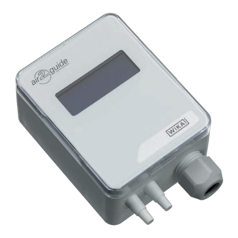
WIKA A2G-30 User manual

Operating instructions
Betriebsanleitung
Mode d'emploi
Manual de instrucciones
Manuale d'uso
GB
Inclined tube manometer model A2G-30
Schrägrohrmanometer Typ A2G-30
Manomètre à tube incliné type A2G-30
Manómetro de tubo inclinado modelo A2G-30
Manometro a tubo inclinato modello A2G-30
Inclined tube manometer model A2G-30
D
F
E
I

WIKA operating instructions air2guide model A2G-30
GB
I
D
F
E
2
40202763.02 07/2012 GB/D/F/E/I
Operating instructions model A2G-30 Page 3-10
Betriebsanleitung Typ A2G-30 Seite 11-18
Mode d'emploi type A2G-30 Page 19-26
Manual de instrucciones modelo A2G-30 Página 27-34
Manuale d'uso modello A2G-30 Pagina 35-42
© 2012 WIKA Alexander Wiegand SE & Co. KG
All rights reserved. / Alle Rechte vorbehalten.
WIKA®is a registered trademark in various countries.
WIKA®ist eine geschützte Marke in verschiedenen Ländern.
Prior to starting any work, read the operating instructions!
Keep for later use!
Vor Beginn aller Arbeiten Betriebsanleitung lesen!
Zum späteren Gebrauch aufbewahren!
Lire le mode d'emploi avant de commencer toute opération !
A conserver pour une utilisation ultérieure !
¡Leer el manual de instrucciones antes de comenzar cualquier trabajo!
¡Guardar el manual para una eventual consulta!
Prima di iniziare ad utilizzare lo strumento, leggere il manuale d‘uso!
Conservare per future consultazioni!

WIKA operating instructions air2guide model A2G-30 3
GB
40202763.02 07/2012 GB/D/F/E/I
1. General information 4
2. Safety 5
3. Specications 6
4. Design and function 8
5. Transport, packaging and storage 8
6. Commissioning, operation 9
7. Options and accessories 10
8. Maintenance and cleaning 10
9. Disposal 10
Contents
Contents

WIKA operating instructions air2guide model A2G-30
GB
4
40202763.02 07/2012 GB/D/F/E/I
1. General information
■
The inclined tube manometer described in the operating instructions
has been designed and manufactured using state-of-the-art
technology. All components are subject to stringent quality and
environmental criteria during production. Our management systems
are certied to ISO 9001 and ISO 14001.
■
These operating instructions contain important information on
handling the instrument. Working safely requires that all safety
instructions and work instructions are observed.
■
Observe the relevant local accident prevention regulations and
general safety regulations for the instrument's range of use.
■
The operating instructions are part of the product and must be kept
in the immediate vicinity of the instrument and readily accessible to
skilled personnel at any time.
■
Skilled personnel must have carefully read and understood the
operating instructions prior to beginning any work.
■
The manufacturer's liability is void in the case of any damage caused
by using the product contrary to its intended use, non-compliance
with these operating instructions, assignment of insuciently
qualied skilled personnel or unauthorised modications to the
instrument.
■
The general terms and conditions contained in the sales
documentation shall apply.
■
Subject to technical modications.
■
Further information:
- Internet address: www.wika.de / www.wika.com
www.air2guide.com
- Relevant data sheet: PM 07.41
WIKA operating instructions air2guide model A2G-30 5
GB
40202763.02 07/2012 GB/D/F/E/I
1. General information / 2. Safety
Explanation of symbols
WARNING!
... indicates a potentially dangerous situation which can
result in serious injury or death if not avoided.
Information
... points out useful tips, recommendations and information
for ecient and trouble-free operation.
2. Safety
WARNING!
Before installation, commissioning and operation, ensure
that the appropriate inclined tube manometer has been
selected in terms of measuring range, design and specic
measuring conditions.
Non-observance can result in serious injury and/or damage
to the equipment.
Further important safety instructions can be found in the
individual chapters of these operating instructions.
2.1 Intended use
This inclined tube manometer is used for the monitoring of ventilators,
blowers and lters in air-conditioning and clean room applications in dry,
clean, non-aggressive gases, primarily air.
The instrument has been designed and built solely for the intended use
described here, and may only be used accordingly.
The manufacturer shall not be liable for claims of any type based on
operation contrary to the intended use.

WIKA operating instructions air2guide model A2G-30
GB
6
40202763.02 07/2012 GB/D/F/E/I
2. Safety / 3. Specications
2.2 Personnel qualication
WARNING!
Risk of injury if qualication is insucient!
Improper handling can result in considerable injury and
damage to equipment.
■
The activities described in these operating instructions
may only be carried out by skilled personnel who have
the qualications described below.
Skilled personnel
Skilled personnel are understood to be personnel who, based on their
technical training, knowledge of measurement and control technology
and on their experience and knowledge of country-specic regulations,
current standards and directives, are capable of carrying out the work
described and independently recognising potential hazards.
Explanation of symbols
CE, Communauté Européenne
Instruments bearing this mark comply with the relevant
European directives.
3. Specications
Accuracy
5 Pa / 25 Pa
Scale range
0 … 600 Pa
Max. pressure
200 kPa (2 bar)
Liquid lling
Red, specic gravity 0.786 kg/dm3 (at 15 °C), 30 ml

WIKA operating instructions air2guide model A2G-30 7
GB
40202763.02 07/2012 GB/D/F/E/I
3. Specications
Process connection
In accordance with the general technical regulations for pressure
gauges (e.g. EN 837-2 "Selection and installation recommendations
for pressure gauges"), connecting nozzles (ABS), for hoses with inner
diameter 4 or 6 mm
Permissible temperature
Ambient: -40 … +60 °C
Operation: -40 … +60 °C
Ingress protection
IP 54 per EN 60529 / lEC 529
Dimensions in mm
For further specications see WIKA data sheet PM 07.41 and the order
documentation.

WIKA operating instructions air2guide model A2G-30
GB
8
40202763.02 07/2012 GB/D/F/E/I
4. Design and function / 5. Transport, packaging ...
4. Design and function
Description
The pressure dierential between the lower and higher pressure is
indicated by the movement of an inclined liquid column.The higher
the pressure, the more the liquid is displaced upwards. A glass tube,
which has been lled with liquid to a specic extent, is used for this. The
pressure can be easily read on the scale.
Scope of delivery
Cross-check the scope of delivery with the delivery note.
5. Transport, packaging and storage
5.1 Transport
Check the inclined tube manometer for any damage that may have been
caused by transport. Obvious damage must be reported immediately.
5.2 Packaging
Do not remove packaging until just before mounting.
Keep the packaging as it will provide optimum protection during
transport (e.g. change in installation site, sending for repair).
5.3 Storage
Permissible conditions at the place of storage
Storage temperature: -40 ... +60 °C
Protect the instruments from moisture and dust.

WIKA operating instructions air2guide model A2G-30 9
GB
40202763.02 07/2012 GB/D/F/E/I
6. Commissioning, operation
Installation
■
The inclined tube manometer must be screw-tted on a suitable
vertical surface
■
The instrument has to be mounted horizontally using the attached
self-tapping screws.
Filling
Turn the zero button back up until the stop. Then turn approximately one
rotation in a clockwise direction, so that the adjustment can be made in
both directions. Unscrew the ll button and ll the measuring instrument
liquid until the liquid is visible near the zero point on the measuring
scale. Make an accurate adjustment with the zero button and then
re-seal the lling hole.
Connection to the air lter
Make the hose connection between the ⊖ connection of the measuring
instrument with the downstream side of the lter and the ⊕ connection
of the measuring instrument with the upstream side of the lter. Stick
the green and red labels next to each other on the scale, in order
to mark the initial (green) and nal pressure (red). Please note the
recommendations of the plant manufacturer regarding the maximum
allowable pressure drop values.
Information
The inclined tube manometer is specially designed
to prevent leakage of the indicator uid in the case of
overpressure.
6. Commissioning, operation

WIKA operating instructions air2guide model A2G-30
GB
10
40202763.02 07/2012 GB/D/F/E/I
7. Options and accessories ... 9. Disposal
7. Options and accessories
Standard accessories
■
2 mounting screws
■
Filling liquid
■
Red and green pressure limitation labels
8. Maintenance and cleaning
Inclined tube manometers are maintenance-free and oer long service
life provided they are handled and operated properly.
Check the indicator liquid regularly and adust the zero point, if required.
Clean the instruments with a moist cloth (soap water).
Repairs must only be carried out by the manufacturer or appropriately
qualied skilled personnel.
9. Disposal
Incorrect disposal can put the environment at risk.
Dispose of instrument components and packaging materials in an
environmentally compatible way and in accordance with the country-
specic waste disposal regulations.

WIKA Betriebsanleitung air2guide Typ A2G-30 11
D
40202763.02 07/2012 GB/D/F/E/I
1. Allgemeines 12
2. Sicherheit 13
3. Technische Daten 14
4. Aufbau und Funktion 16
5. Transport, Verpackung und Lagerung 16
6. Inbetriebnahme, Betrieb 17
7. Optionen und Zubehör 18
8. Wartung und Reinigung 18
9. Entsorgung 18
Inhalt
Inhalt

D
WIKA Betriebsanleitung air2guide Typ A2G-30
12
40202763.02 07/2012 GB/D/F/E/I
1. Allgemeines
1. Allgemeines
■
Das in der Betriebsanleitung beschriebene Schrägrohrmanometer
wird nach nach dem aktuellen Stand der Technik konstruiert und
gefertigt. Alle Komponenten unterliegen während der Fertigung
strengen Qualitäts- und Umweltkriterien. Unsere Managementsy-
steme sind nach ISO 9001 und ISO 14001 zertiziert.
■
Diese Betriebsanleitung gibt wichtige Hinweise zum Umgang mit
dem Gerät.Voraussetzung für sicheres Arbeiten ist die Einhaltung
aller angegebenen Sicherheitshinweise und Handlungsanwei-
sungen.
■
Die für den Einsatzbereich des Gerätes geltenden örtlichen Unfall-
verhütungsvorschriften und allgemeinen Sicherheitsbestimmungen
einhalten.
■
Die Betriebsanleitung ist Produktbestandteil und muss in unmittel-
barer Nähe des Gerätes für das Fachpersonal jederzeit zugänglich
aufbewahrt werden.
■
Das Fachpersonal muss die Betriebsanleitung vor Beginn aller
Arbeiten sorgfältig durchgelesen und verstanden haben.
■
Die Haftung des Herstellers erlischt bei Schäden durch bestim-
mungswidrige Verwendung, Nichtbeachten dieser Betriebsanleitung,
Einsatz ungenügend qualizierten Fachpersonals sowie eigenmäch-
tiger Veränderung am Gerät.
■
Es gelten die allgemeinen Geschäftsbedingungen in den Verkaufs-
unterlagen.
■
Technische Änderungen vorbehalten.
■
Weitere Informationen:
- Internet-Adresse: www.wika.de / www.wika.com
www.air2guide.com
- zugehöriges Datenblatt: PM 07.41

WIKA Betriebsanleitung air2guide Typ A2G-30 13
D
40202763.02 07/2012 GB/D/F/E/I
1. Allgemeines / 2. Sicherheit
Symbolerklärung
WARNUNG!
… weist auf eine möglicherweise gefährliche Situation hin,
die zum Tod oder zu schweren Verletzungen führen kann,
wenn sie nicht gemieden wird.
Information
… hebt nützliche Tipps und Empfehlungen sowie Infor-
mationen für einen ezienten und störungsfreien Betrieb
hervor.
2. Sicherheit
WARNUNG!
Vor Montage, Inbetriebnahme und Betrieb sicherstellen,
dass das richtige Schrägrohrmanometer hinsichtlich
Messbereich, Ausführung und spezischen Messbedin-
gungen ausgewählt wurde.
Bei Nichtbeachten können schwere Körperverletzungen
und/oder Sachschäden auftreten.
Weitere wichtige Sicherheitshinweise benden sich in den
einzelnen Kapiteln dieser Betriebsanleitung.
2.1 Bestimmungsgemäße Verwendung
Dieses Schrägrohrmanometer dient zur Überwachung von Ventilatoren,
Gebläsen und Filtern in der Klima- und Reinraumtechnik bei trockenen,
sauberen, nicht aggressiven Gasen, hauptsächlich Luft.
Das Gerät ist ausschließlich für den hier beschriebenen bestimmungs-
gemäßen Verwendungszweck konzipiert und konstruiert und darf nur
dementsprechend verwendet werden.
Ansprüche jeglicher Art aufgrund von nicht bestimmungsgemäßer
Verwendung sind ausgeschlossen.

D
WIKA Betriebsanleitung air2guide Typ A2G-30
14
40202763.02 07/2012 GB/D/F/E/I
2. Sicherheit / 3. Technische Daten
2.2 Personalqualikation
WARNUNG!
Verletzungsgefahr bei unzureichender Qualikation!
Unsachgemäßer Umgang kann zu erheblichen Personen-
und Sachschäden führen.
■
Die in dieser Betriebsanleitung beschriebenen Tätig-
keiten nur durch Fachpersonal nachfolgend beschrie-
bener Qualikation durchführen lassen.
Fachpersonal
Das Fachpersonal ist aufgrund seiner fachlichen Ausbildung, seiner
Kenntnisse der Mess- und Regelungstechnik und seiner Erfahrungen
sowie Kenntnis der landesspezischen Vorschriften, geltenden Normen
und Richtlinien in der Lage, die beschriebenen Arbeiten auszuführen
und mögliche Gefahren selbstständig zu erkennen.
Symbolerklärung
CE, Communauté Européenne
Geräte mit dieser Kennzeichnung stimmen überein mit den
zutreenden europäischen Richtlinien.
3. Technische Daten
Genauigkeit
5 Pa / 25 Pa
Anzeigebereich
0 … 600 Pa
Max. Druck
200 kPa (2 bar)
Flüssigkeitsfüllung
Rot, Dichte 0,786 kg/dm3 (bei 15 °C), 30 ml

WIKA Betriebsanleitung air2guide Typ A2G-30 15
D
40202763.02 07/2012 GB/D/F/E/I
3. Technische Daten
Prozessanschluss
Entsprechend den allgemeinen technischen Regeln für Druckmess-
geräte (z. B. EN 837-2 "Auswahl- und Einbauempfehlungen für Druck-
messgeräte"), Anschlussstutzen (ABS), für Schläuche mit Innendurch-
messer 4 oder 6 mm
Zulässige Temperatur
Umgebung: -40 … +60 °C
Betrieb: -40 … +60 °C
Schutzart
IP 54 nach EN 60529 / lEC 529
Abmessungen in mm
Weitere technische Daten siehe WIKA-Datenblatt PM 07.41 und
Bestellunterlagen.

D
WIKA Betriebsanleitung air2guide Typ A2G-30
16
40202763.02 07/2012 GB/D/F/E/I
4. Aufbau und Funktion / 5. Transport, Verpackung ...
4. Aufbau und Funktion
Beschreibung
Die Druckdierenz zwischen den niedrigen und höherem Druck
wird durch Verschieben einer schrägen Flüssigkeitssäule angezeigt.
Je höher der Druck, desto stärker wird die Flüssigkeit nach oben
verdrängt. Dazu wird ein Glasrohr verwendet, das zu einem gewissen
Teil mit Flüssigkeit gefüllt wurde. Der Druck lässt sich auf der Skala
einfach ablesen.
Lieferumfang
Lieferumfang mit dem Lieferschein abgleichen.
5. Transport, Verpackung und Lagerung
5.1 Transport
Schrägrohrmanometer auf eventuell vorhandene Transportschäden
untersuchen. Oensichtliche Schäden unverzüglich mitteilen.
5.2 Verpackung
Verpackung erst unmittelbar vor der Montage entfernen.
Die Verpackung aufbewahren, denn diese bietet bei einem Transport
einen optimalen Schutz (z. B. wechselnder Einbauort, Reparatursen-
dung).
5.3 Lagerung
Zulässige Bedingungen am Lagerort
Lagertemperatur: -40 ... +60 °C
Geräte vor Feuchtigkeit und Staub schützen.

WIKA Betriebsanleitung air2guide Typ A2G-30 17
D
40202763.02 07/2012 GB/D/F/E/I
6. Inbetriebnahme, Betrieb
Installation
■
Das Schrägrohrmanometer muss auf einer geeigneten vertikalen
Fläche aufgeschraubt werden
■
Das Gerät ist waagrecht mit den beiliegenden selbstschneidenden
Schrauben zu befestigen
Füllung
Null-Knopf bis zum Anschlag zurück drehen, danach etwa eine
Drehung im Uhrzeigersinn drehen, so dass die Einstellung in beide
Richtungen vorgenommen werden kann. Füllknopf abschrauben und
mit der Messgeräteüssigkeit füllen, bis sich die Flüssigkeit sichtbar
in der Nähe des Nullpunktes auf der Messskala bendet. Eine exakte
Einstellung mit dem Null-Knopf vornehmen und das Füllloch wieder
verschließen.
Anschluss an den Luftlter
Schlauchverbindung zwischen dem Anschluss ⊖ des Messgerätes mit
der Abströmseite des Filters sowie dem Anschluss ⊕ des Messgerätes
mit der Anströmseite des Filters herstellen. Die grünen und roten
Etiketten an der Skala nebeneinander aufkleben, um Anfangs-
(grün) und Enddruck (rot) zu markieren. Bitte die Empfehlungen des
Anlagenherstellers bezüglich der höchstzulässigen Druckverlustwerte
beachten.
Information
Durch die spezielle Bauweise des Schrägrohrmanometers
wird bei Überdruck ein Auslaufen der Anzeigeüssigkeit
verhindert.
6. Inbetriebnahme, Betrieb

D
WIKA Betriebsanleitung air2guide Typ A2G-30
18
40202763.02 07/2012 GB/D/F/E/I
7. Optionen und Zubehör ... 9. Entsorgung
7. Optionen und Zubehör
Standardzubehör
■
2 Befestigungsschrauben
■
Füllüssigkeit
■
Rote und grüne Drucklimit-Aufkleber
8. Wartung und Reinigung
Schrägrohrmanometer sind wartungsfrei und zeichnen sich bei sachge-
mäßer Behandlung und Bedienung durch eine hohe Lebensdauer aus.
Die Anzeigeüssigkeit regelmäßig kontrollieren und bei Bedarf
Nullpunkt nachstellen.
Reinigen der Geräte mit einem (in Seifenlauge) angefeuchteten Tuch.
Reparaturen sind ausschließlich vom Hersteller oder entsprechend
qualiziertem Fachpersonal durchzuführen.
9. Entsorgung
Durch falsche Entsorgung können Gefahren für die Umwelt entstehen.
Gerätekomponenten und Verpackungsmaterialien entsprechend den
landesspezischen Abfallbehandlungs- und Entsorgungsvorschriften
umweltgerecht entsorgen.

Mode d´emploi WIKA air2guide type A2G-30 19
F
40202763.02 07/2012 GB/D/F/E/I
1. Généralités 20
2. Sécurité 21
3. Spécications 22
4. Conception et fonction 24
5. Transport, emballage et stockage 24
6. Mise en service, exploitation 25
7. Options et accessoires 26
8. Entretien et nettoyage 26
9. Mise au rebut 26
Sommaire
Sommaire

F
Mode d´emploi WIKA air2guide type A2G-30
20
40202763.02 07/2012 GB/D/F/E/I
1. Généralités
1. Généralités
■
Le manomètre à tube incliné décrit dans le mode d'emploi est
conçu et fabriqué selon les dernières technologies en vigueur.
Tous les composants sont soumis à des critères de qualité et
d'environnement stricts durant la fabrication. Nos systèmes de
gestion sont certiés selon ISO 9001 et ISO 14001.
■
Ce mode d'emploi donne des indications importantes concernant
l'utilisation de l'instrument. Il est possible de travailler en toute
sécurité avec ce produit en respectant toutes les consignes de
sécurité et d'utilisation.
■
Respecter les prescriptions locales de prévention contre les
accidents et les prescriptions générales de sécurité en vigueur pour
le domaine d‘application de l'instrument.
■
Le mode d'emploi fait partie du produit et doit être conservé à
proximité immédiate de l'instrument et être accessible à tout moment
pour le personnel qualié.
■
Le personnel qualié doit, avant de commencer toute opération,
avoir lu soigneusement et compris le mode d'emploi.
■
La responsabilité du fabricant n'est pas engagée en cas de
dommages provoqués par une utilisation non conforme à l'usage
prévu, de non respect de ce mode d'emploi, d'utilisation de
personnel peu qualié de même qu'en cas de modications de
l'instrument eectuées par l'utilisateur.
■
Les conditions générales de vente mentionnées dans les documents
de vente s'appliquent.
■
Sous réserve de modications techniques.
■
Pour obtenir d'autres informations :
- Consulter notre site internet : www.wika.fr / www.wika.com
www.air2guide.com
- Fiche technique correspondante : PM 07.41
Table of contents
Languages:
Other WIKA Measuring Instrument manuals

WIKA
WIKA CTD9300 Series User manual

WIKA
WIKA NS 63 User manual

WIKA
WIKA SERIES CPG 2500 User manual

WIKA
WIKA 4x2.30.1x0 Series User manual

WIKA
WIKA PG81 User manual

WIKA
WIKA 5 User manual

WIKA
WIKA CPG2300 Series User manual

WIKA
WIKA PGW23.100.11 User manual

WIKA
WIKA 821 User manual

WIKA
WIKA PGS23 User manual

WIKA
WIKA PGS10 User manual

WIKA
WIKA CPH6400 User manual

WIKA
WIKA DI32-1 User manual

WIKA
WIKA 632.50.100 User manual

WIKA
WIKA intelliTHERM TGT70 User manual

WIKA
WIKA RVM/U-L-1 User manual

WIKA
WIKA CPG500 User manual

WIKA
WIKA 212.20.100 User manual

WIKA
WIKA 73 02.100 Series User manual

WIKA
WIKA DELTA-trans DPGT40 User manual