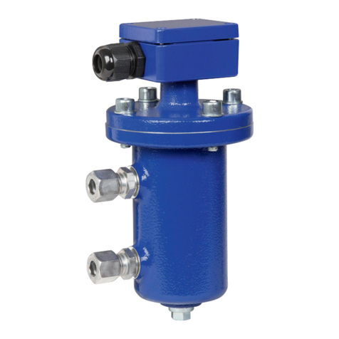
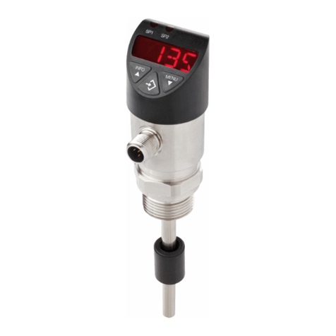
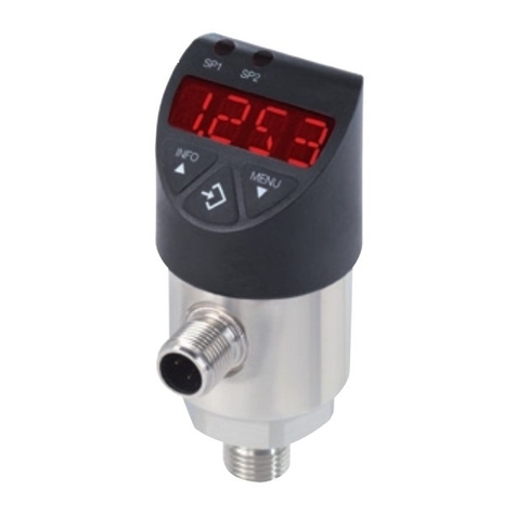
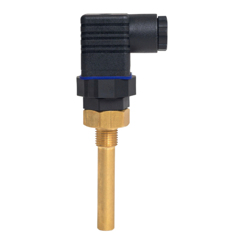
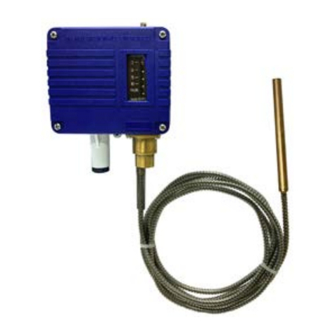
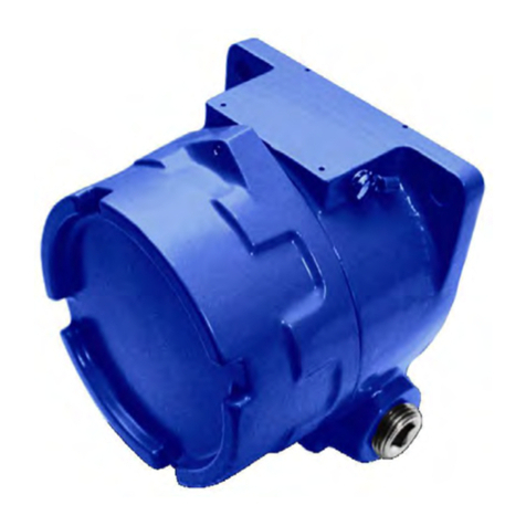
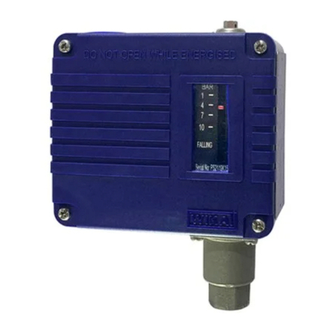
WIKA TLS User manual

CN
EN
Operating instructions
操作说明书
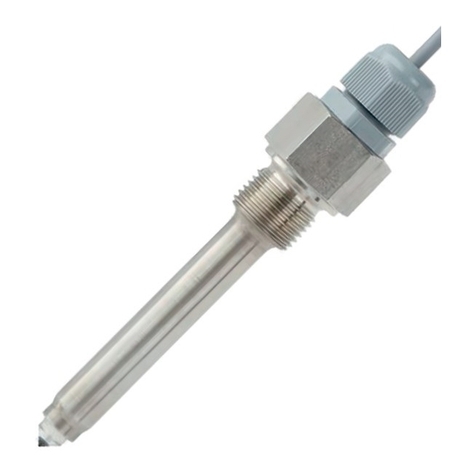
Tuning fork level switch, model TLS
音叉物位开关,型号TLS
Type PI
Thread connection
螺纹连接
Type IN
Thread and chuck connection
螺纹和卡盘连接

2
001888.05 06/2023 EN/CN
CN
EN Operating Instructions, Model TLS Page 3 - 39
操作说明,型号 TLS 页面 41 - 75
© 2016 WIKA Alexander Wiegand SE & Co. KG
All rights reserved. / 保留所有权利。
WIKA®and KSR®are registered trademarks in various countries.
WIKA®和KSR®是威卡(WIKA)在各个国家的注册商标。
Prior to starting any work, read the operating instructions!
Keep for later use!
在开始任何工作之前, 请仔细阅读操作说明!
请妥善保留以备后用!
Operating instructions, tuning fork level switch, model TLS

EN
Operating instructions, tuning fork level switch, model TLS
001888.05 06/2023 EN/CN
3
Contents
Contents
Declarations of conformity can be found online at www.wika.com.
1. General information 4
2. Design and function 5
3. Safety 6
4. Transport, packaging and storage 11
5. Commissioning, operation 11
6. Faults 33
7. Maintenance and cleaning 36
8. Dismounting, return and disposal 37
9. Specications 38

EN
001888.05 06/2023 EN/CN
4Operating instructions, tuning fork level switch, model TLS
1. General information
■
The tuning fork level switches described in the operating instructions
have been designed and manufactured using state-of-the-art
technology. All components are subject to stringent quality and
environmental criteria during production. Our management systems
are certied to ISO 9001.
■
These operating instructions contain important information on
handling the instrument. Working safely requires that all safety
instructions and work instructions are observed.
■
Observe the relevant local accident prevention regulations and
general safety regulations for the instrument’s range of use.
■
The operating instructions are part of the product and must be kept
in the immediate vicinity of the instrument and readily accessible to
skilled personnel at any time. Pass the operating instructions on to
the next operator or owner of the instrument.
■
Skilled personnel must have carefully read and understood the
operating instructions prior to beginning any work.
■
The general terms and conditions contained in the sales
documentation shall apply.
■
Subject to technical modications.
■
Further information:
- Internet address: www.wika.com
- Relevant data sheet: DS_TLS_EN_02.2023
1. General information

1
2
3
4
5
EN
Operating instructions, tuning fork level switch, model TLS
001888.05 06/2023 EN/CN
5
2. Design and function
2.1 Functional description
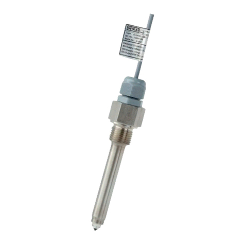
Tuning fork level switch is a universal level switch. The core component
of the tuning fork level switch is the vibration drive device located in the
fork body, which drives the fork body to reach its resonant frequency.
When the fork body is immersed by the medium, the frequency of the
fork body decreases, and the frequency change is detected by the
electronic circuit and converted into a switching signal to achieve the
purpose of liquid level alarm or control.
Connection housing
Cable gland
Mounting thread
Extension tube
Tuning fork
2.2 Scope of delivery
Cross-check scope of delivery with delivery note.
2. Design and function

EN
001888.05 06/2023 EN/CN
6Operating instructions, tuning fork level switch, model TLS
3. Safety
3.1 Symbols
DANGER!
... indicates an immediately hazardous situation which might
result in death or severe injuries if it is not avoided.
WARNING!
... indicates an potentially hazardous situation which might
result in death or severe injuries if it is not avoided.
CAUTION!
... indicates an potentially hazardous situation which might
result in light or minor injuries or property or environmental
damages if it is not avoided.
Information
... highlights useful tips and recommendations and
information for ecient and fault-free operation.
3.2 Proper intended use
Tuning fork level switches are solely intended for monitoring the liquid
level of uids. The area of use is based on the technical performance
limits and materials.
■
The viscosity and density of the medium should meet the following
requirements:
The viscosity of the medium is 0.1~10000 cP.
The medium density is 0.5~2.5 g/cm3.
■
Compliance with the usage conditions specied in the operating
instructions is required.
3. Safety

EN
Operating instructions, tuning fork level switch, model TLS
001888.05 06/2023 EN/CN
7
■
Tuning fork level switch may not be subjected to strong mechanical
stresses (im- pact, bending, vibrations).The unit is exclusively
designed and constructed for the intended use described here and
may only be used accordingly.
■
The switching points of the tuning fork level switch(IN) cannot be
adjusted.
■
Compliance with the relevant safety regulations for the use is
required.
■
Compliance with the technical specications in these operating
instructions is required. Improper use or operation of the unit outside
the technical specications requires immediate shut-down and
inspection by an authorized WIKA service technician.
Claims of any kind due to improper use are excluded.
DANGER!
When working on containers, there is a risk of poisoning or
suocation. Work may only be performed using suitable
personal safety equipment (e.g. respiratory protection,
protective clothing, etc.).
3. Safety

EN
001888.05 06/2023 EN/CN
8Operating instructions, tuning fork level switch, model TLS
3.3 Improper use
Any use that exceeds the technical performance thresholds or that is
incompatible with the materials is considered improper use.
WARNING!
Injury due to improper use
Improper use of the unit can result in hazardous situations
and injuries.
Do not modify the unit without authorization.
Any use beyond the proper intended use or any other use is considered
improper use.
Do not use this unit in safety or emergency o equipment.
3.4 Responsibility of the operator
The unit is used in the industrial sector. The operator is therefore subject
to statutory obligations with respect to occupational safety.
Compliance with the safety instructions in these operating instructions
and the applicable safety, accident prevention and environmental
protection regulations for the area of use of the unit is required.
In order to safely work on the unit, the operator must ensure
■
the operating personnel is regularly trained in all matters pertaining
to occupational safety, rst aid and environmental conservation and
is familiar with the operating instructions and, in particular, the safety
instructions contained therein.
■
the unit is suitable for the application in accordance with the proper
intended use (check for improper use).
3. Safety
EN
Operating instructions, tuning fork level switch, model TLS
001888.05 06/2023 EN/CN
9
3.5 Personnelqualication
WARNING!
Riskofinjuryduetoinsucientqualications
Improper use can result in signicant personal injury and
property damages.
•
The activities described in these operating instructions
may only be performed by specialist technicians with the
following qualifications.
Specialist personnel
The specialist personnel authorized by the operator is capable of
executing the described work and autonomously detect potential
hazards due their technical training, knowledge of measuring and control
technology and their experience and knowledge of country-specic
regulations, applicable standards and guidelines.
3.6 Personal safety equipment
The personal safety equipment serves to protect the technicians against
hazards that might impact the safety or health while working. When
executing the various tasks on and with the unit, the technicians must
wear personal safety equipment.
Comply with warning signs posted in the work area regarding
personal safety equipment!
The required personal safety equipment must be provided by the
operator.
3. Safety

EN
001888.05 06/2023 EN/CN
10 Operating instructions, tuning fork level switch, model TLS
3.7 Labelling, safety markings
Product label (examples)
Shanghai KSR-KUEBLER Automation Instrument Co., Ltd.
No.2, Lane 699 Yuyang Road Songjiang District, Shanghai China
A division of theWIKA Group
1
2
3
4
5
6
79810
Product name
Product model
Tag number
Operating temperature
Power supply
Serial number
Operating pressure
Insertion length
Signal output
Information of Ex
Symbols
Before mounting and commissioning the instrument,
ensure you read the operating instructions!
3. Safety

EN
Operating instructions, tuning fork level switch, model TLS
001888.05 06/2023 EN/CN
11
4. Transport, packaging and storage
4.1 Transport
Check the tuning fork level switch for any damage that may have been
caused by transport. Obvious damage must be reported immediately.
CAUTION!
Damage due to improper transport
With improper transport, a high level of damage to property
can occur.
Observe the symbols on the packaging.
Handle packages with care.
4.2 Transport and storage
Do not remove packaging until just before commissioning.
5. Commissioning, operation
■
Observe all instructions provided on the packaging for removing the
transportation safety devices.
■
Remove the tuning fork level switch carefully from the packaging!
■
When unpacking, check all components for any external damage.
5.1 Mounting preparations
Functional check
Before mounting, the level switch can be connected as
described in chapter 5.3 and the switch points can be
operated manually.
WARNING!
Ensure that the functional check does not start any
unintended processes.
4. Transport ... / 5. Commissioning, operation

EN
001888.05 06/2023 EN/CN
12 Operating instructions, tuning fork level switch, model TLS
5.2 Mounting
■
Observe the torque values of screws specied in pipetting work.
■
In the selection of the mounting material (seals, bolts, washers and
nuts), take the process conditions into account. The suitability of the
sealing must be specied with regard to the medium and its vapours.
In addition, ensure it has corresponding corrosion resistance.
■
Ensure that the sealing faces of the vessel and tuning fork level
switch are clean and do not show any mechanical damage
■
Thread mounting
Note: The direction mark of the tuning fork must be upward when
installing.
1) L: make sure there is enough space between the tank wall the
tuning fork where adhesion may occur.
L L
Direction mark
of tuning fork Direction mark
of tuning fork
2) If the tuning fork is indented into the tube holder and the medium
viscosity range is 0~2000mm2/s, the distance between the end of
the fork and the tank wall should be ≥ 25mm.
≥25mm ≥25mm
Direction mark
of tuning fork Direction mark
of tuning fork
5. Commissioning, operation

EN
Operating instructions, tuning fork level switch, model TLS
001888.05 06/2023 EN/CN
13
■
Flange / chuck mounting
Note: The direction of tuning fork is shown in the gure below.
1) L: make sure there is enough space between the tank wall the
tuning fork where adhesion may occur.
L L
2) If the tuning fork is indented into the welded pipe and the medium
viscosity range is 0~2000mm2/s, the nominal diameter of the
welded pipe is at least DN50 (ange) / 2” (chuck).
≥
DN50
≥
2''
■
Pipe mounting
Note: When installed in the pipe, the direction of the tuning fork is
consistent with the direction of uid ow.
5. Commissioning, operation

EN
001888.05 06/2023 EN/CN
14 Operating instructions, tuning fork level switch, model TLS
5.3 Electrical connection
■
The electrical connection must only be made by qualied skilled
personnel.
■
Connection details and switching functions are given on the
connection diagram on the instrument and the connection terminals
are appropriately marked.
■
The mains connection lines to be provided must be dimensioned
for maximum instrument current supply and comply with IEC 227 or
IEC 245.
■
The cables installed on the product are designed for xed installation.
DANGER!
The electrical connection must be made in a de-energised
state.
WARNING!
Electrical connection errors of the tuning fork level switches
can destroy the reed contacts. This can lead to a malfunction
in the plant and thus lead to injury to personnel or damage to
equipment.
Explosion-proof instrument, only when there is no detonating
atmosphere, it is allowed to open the lid of the junction box.
Wiring steps
For PI model TLS-S, the operation steps are as follows.
1) Unscrew the cover of the terminal box;
2) Unscrew the locking nut on the cable lock;
3) Remove the outer covering of the cable about 10cm, and
remove the insulation layer at the end of the core wire about
1cm;
4) Pass the cable through the cable lock and insert it into the
terminal box;
5) Loosen the bolt of the wiring terminal with the supporting
screwdriver;
6) Insert the end of the core wire into the wiring port of the
wiring terminal according to the wiring diagram;
7) Tighten the bolt of the wiring terminal with the supporting
screwdriver;
5. Commissioning, operation

EN
Operating instructions, tuning fork level switch, model TLS
001888.05 06/2023 EN/CN
15
8) Check whether the terminal wiring is rm by gently pulling
the core wire;
9) Tighten the locking nut of the cable lock;
10) Screw on the terminal box cover;
11) The electrical connection is completed.
For IN model-ASC4 TLS-C/H, the operation steps are as
follows.
1) Loosen the screw at the top of the plug and disassemble
the plug and socket;
2) Unscrew the cable connector of the plug and remove the
terminal in the plug;
3) Remove the outer skin of the connecting cable about 5cm
and the core wire insulation about 1cm;
4) Put the cable through the cable connector and insert it into
the plug shell;
5) Connect the end of the core wire with the terminal
according to the wiring diagram;
6) Clip the terminal into the plug shell;
7) Install the plug and socket, and tighten the screw at the
top of the plug.
For IN model-M12 TLS-C/H, the operation steps are as
follows.
1) Take out the M12 aviation socket (cable with specied
length at the end);
2) Align the positioning bent of the M12 aviation socket with
the positioning bump of the aviation plug on the tuning fork
switch body;
3) Press the end of the M12 aviation socket to ensure that
the socket inserts the plug according to the positioning
position;
4) Tighten the locking nut outside the M12 aviation socket;
5) Make sure the connection of M12 aviation socket and plug
is reliable.
5. Commissioning, operation

EN
001888.05 06/2023 EN/CN
16 Operating instructions, tuning fork level switch, model TLS
Connections diagrams
PI model TLS-S
<Please refer to the manual for the detail of wiring diagram>
Relay output DPDT
Power supply is AC 220V or
DC 24V, specify one when
ordering.
+
-
12 3 4 5 6 7 8
Power
Supply
Transistor
output PNP
Power supply is
DC 24V.
+
-
12 3
DC 24V Load
NAMUR
Power supply is
DC 8.2V.
+
-
12 3
DC 8.2V
IN model-ASC4 TLS-C/H
<Please refer to the manual for the detail of wiring diagram>
Transistor output PNP
Power supply is DC 24V.
1 2
3
1 2
3
DC 24V
+
-
D
C 24V
+
-
Load
Max. Mix.
Load
Relay output SPST
Power supply is DC 24V.
1 2
3
DC 24V
+
-
OUT
IN model-M12 TLS-C/H
<Please refer to the manual for the detail of wiring diagram>
5. Commissioning, operation

EN
Operating instructions, tuning fork level switch, model TLS
001888.05 06/2023 EN/CN
17
Transistor output PNP
Power supply is DC 24V.
12
3
4
12
3
4
DC 24V
+
-DC 24V
+
-
Load
Max. Mix.
Load
Relay output SPST
Power supply is DC 24V.
DC 24V
+
-
1 2
3
4
Abbreviations,denitions
SPST Normally open/normally closed
DPDT Change-over
5. Commissioning, operation

EN
001888.05 06/2023 EN/CN
18 Operating instructions, tuning fork level switch, model TLS
5.4 Commissioning
Typically, the operating point of the switching on-o signal is
perfected when the product leaves the factory. Under normal
circumstances, no further adjustments are required.
Action point
The tuning fork can measure the minimum density of the
medium up to 0.5g/cm3.
The length of tuning fork is 38mm, 42mm.
1) The length of tuning fork is 38mm
If the tuning fork is mounted vertically downward, the action
point of the tuning fork level switch is 13mm.
If the tuning fork is mounted vertically upward, the action
point of the tuning fork is 32mm.
If the tuning fork is mounted horizontally, the action point of
the tuning fork level switch is 4mm.
Note: the action point is set in the factory, and the reference
medium is water.
32
13
4
5. Commissioning, operation

EN
Operating instructions, tuning fork level switch, model TLS
001888.05 06/2023 EN/CN
19
2) The length of fork body is 42mm
If the tuning fork is mounted vertically downward, the action
point of the tuning fork level switch is 13mm.
If the tuning fork is mounted vertically upward, the action
point of the tuning fork level switch is 37mm.
If the tuning fork is mounted horizontally, the action point of
the tuning fork level switch is 4mm.
Note: the action point is set in the factory, and the reference
medium is water.
13
37
4
Performance
The accuracy of the tuning fork level switch is ±2mm.
The switching dierence of the tuning fork level switch ≤3mm.
The repeatability of the tuning fork level switch is 0.1mm.
Response time (default):
When the tuning fork is changed from no medium covered
to medium covered and reaches the setting action point, the
respond time is 0.5s.
In contrast, when the tuning fork is changed from medium
covered to no medium covered and reaches the setting
action point, the respond time is 1s.
5. Commissioning, operation

EN
001888.05 06/2023 EN/CN
20 Operating instructions, tuning fork level switch, model TLS
Function indication
1. PI model TLS-S
1) Wiring terminal
Terminal 1 is connected to the positive pole of the power
supply, terminal 2 is connected to the negative pole of the
power supply.
Signal output Relay DPDT: terminals 4 and 7 are public
ends, terminals 3 and 6 are normally closed contacts, and
terminals 5 and 8 are normally open contacts.
Signal output PNP: terminal 3 is signal output.
Signal output NAMUR: terminal 3 is GND.
2) Indicator light
Facing forward to the instrument panel, the left side is signal
output and power supply indicator light.
3) Regulating element
There are 10 levels of adjustment from 0 to 9 in two code
dials, and there are indicating arrows in the middle of the
code dials. The screwdriver is used for dierent levels of
adjustment. Facing forward to the instrument panel, the
left side is delay setting and the right side is sensitivity
adjustment.
4) Mode switch button
Facing forward to the instrument panel, the right side is the
button of mode switch.
5
4
3
2
1
0
9
8
7
6
5
4
3
2
1
0
9
8
7
6
12 3 4 5 6 7 8
0(s)
1
2
3
4
6
8
10
15
20
0
1
2
3
4
5
6
7
8
9
Output delay adjuster
Indicator
light
Delay setting Dial
Max-Min
switch button
Sensitivity adjuster
5. Commissioning, operation
Table of contents
Other WIKA Switch manuals
Popular Switch manuals by other brands

AJAX
AJAX Hub 2 Plus manual

PCB Piezotronics
PCB Piezotronics IMI SENSORS EP686B71 Installation and operating manual

D-Link
D-Link DES-3250TG Reference manual

steute
steute Ex 13 Series Mounting and wiring instructions

Endress+Hauser
Endress+Hauser Liquiphant FTL64 operating instructions

Magnetrol
Magnetrol AMETEK T62 Installation and operating manual