manuals.online logo
Brands
  1. Home
  2. •
  3. Brands
  4. •
  5. Seametrics
  6. •
  7. Measuring Instrument
  8. •
  9. Seametrics FT522 User manual

Seametrics FT522 User manual

FT522 Usage Monitor
Instructions
LT-10829-A
Page 1 of 4
General Information Specifications
Power 115/220 VAC, 50/60 Hz,
12-24 VDC
Temperature 32°- 130°F (0°- 55°C)
Enclosure Precision cast aluminum,
NEMA 4X
Alarm Outputs Two Form C SPDT relay,
115 VAC 5A max
Max Pulse Output 100 mA at 60 VDC
MemoryType Non-volatile EEPROM
auto-backup
Sensor Power 12 VDC, 10 mA
Totalizer 8 digit
Rate Display 5 digit
Volume Units Gallons, cubic feet, cubic
meters
Time Units Minutes, hours
Analog Output 4-20 mA, 0-10 VDC,
opto-isolated
Sensor Input Open collector current sink,
ESD protected
Max Input Frequency 1,000 Hz
ShippingWeight 7 lbs
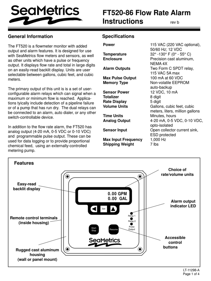
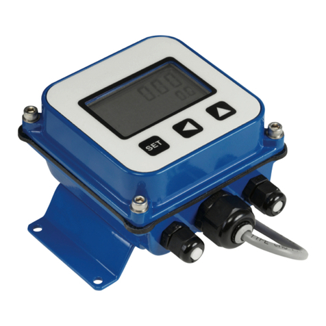
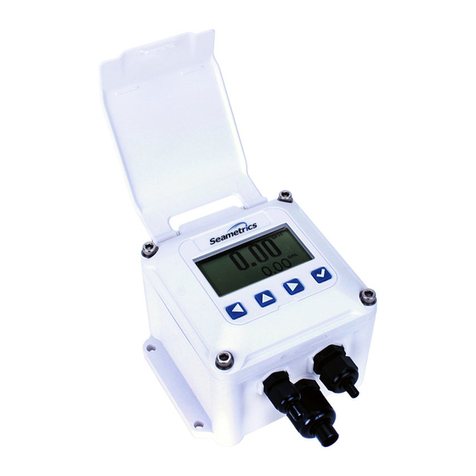
TheFT522 isa flowmetermonitor withadded outputand
alarm features. It is designed for use with SeaMetrics
flow meters and sensors, as well as other units which
have a pulse or frequency output. It displays flow rate
and total in large digits on an easily-read backlit display.
Units are user selectable between gallons, cubic feet,
and cubic meters.
The primary output of this unit is a user-set alarm relay
which signals excess total flow within a given time pe-
riod (up to 48 hours).This is typically used to detect an
overly highusagelevelina coolingtowerorpotablewater
application. The dual relays can be connected to an
alarm, autodialer, or any other switch-controllable
device.
In addition to the usage alarm, the FT522 has analog
output (4-20 mA, 0-10 VDC) and programmable pulse
output.These can be used for data logging or to provide
proportionalchemical feed,using anexternally-controlled
metering pump.
Features
Relay 1
Relay 2
Pulse
Output
0:00:00
0 GAL
ELAPSED
Set
Resume
Stop
Easy-read
backlit display
Remote control terminals
(inside housing)
Rugged cast aluminum
housing
(wall or panel mount)
Choice of
rate/volume units
Alarm output
indicator LED
Accessible
control buttons
ARCHIVED
Installation
Wall Mounting. Usingthe eightscrewsprovided,attach
the two foot brackets to the sides of the enclosure.Then
attachthe unit toany securesurfacebyinserting screws
through the mounting holes in the foot brackets.
Panel Mounting. Followthe dimensionsgivenfor“Panel
Cutout”.Be sure to include the four corner screw holes.
Aftercutting anddrilling,place the frontplate onthe front
side of the panel with its gasket against the panel, and
the remainder of the square housing on the back side.
Slide the screws through the four holes drilled in the
panel,andintothethreaded holesinthe housing.Tighten
until the gasket is firmly compressed against the panel.
ExposeTerminals. Removethefourscrewswhich hold
the front plate to its flange.Remove the front plate.The
display board is attached to this front plate. It is also
connected to the power board by a ribbon cable. For
convenience, this cable can be disconnected, or the
display board can be allowed to dangle while making
connections. Connections can be made inside the
enclosure, or the terminals can be unplugged for easier
access, by gently tugging on them.
Sensor Connection. Followthe“Connections”diagram
to connect either two or three wires from the flow meter
or flow sensor.
Monitor Alarm Connection.Connect thealarm devices
to the appropriate relay terminals. Note that the relays
haveboth normally-open (NO)andnormally-closed(NC)
contacts.
Power Connection. Connect AC or DC power as
desired to the appropriate terminals. For safety, if using
AC power, be sure to connect the ground terminal
provided to a good earth ground.
Replace the front panel, taking care to reconnect the
ribbon cable if it has been disconnected.When power is
switched on,the displayshould light upimmediately with
meaningful letters or digits.
Settings
Set Units. Use to select volume units. Use to
select the particular unit desired (gallons, liters, etc.).
Then use to switch to time units. Again, select the
one desired.
Set Time Period. This is the monitoring period at the
endof which theunit willalarm iftotal flowhas exceeded
its setting.To set this monitoring period in hours, use the
and keys.The digit which is underlined is the one
being set. Use the to increase it.The moves one
digit to the left. Note that if the digit to the right is set to
“9”, the digit to the left will only go to“3”.This is because
48 is the maximum setting allowed.
Set Alarm Point. This is the maximum total flow al-
lowed in the time period set above.Use the same proce-
dure as above to set this value, up to nine digits. The
units are as shown (previously chosen).
Set K-Factor. The unit will not function properly until
this number is entered.It is simply the number of pulses
which the flow meter or flow sensor puts out per gallon
of liquid. It is marked on the Model/Serial tag of
SeaMetrics flow meters and flow sensor fittings. On
Caution: When the control is
powered up,relay or analog out-
puts may be present. If this
could be a hazard, wait to make
external connections until pro-
gramming is complete.
2 of 4
!
SETTINGSOPERATION MODE
SET
SET
SET
SET
SET
SET
SET
SET
Time Period:
12 HOURS
Alarm Point:
1234 GAL
TO CLEAR TOTAL
PRESS UP & LEFT
SET 20mA RATE
0.00 GPM
return to
operation mode
Flow
Monitor
SET PULSE OUT
123 GAL
SET K-FACTOR
123.456
GAL
MINUTE
Units
0:00:00
0 GAL
ELAPSED
0 GPM
0 GAL
Displays
ARCHIVED
adjustableflowsensors,the K-factormustbetaken from
the chart in the flow sensor instructions, based on pipe
size.Set using the same procedure as above.
Set Pulse Out. An output pulse is activated at the se-
lected volume intervals if this feature is in use. Other-
wise, it does not need to be set.
Set 20 mA Out. A 4-20 mA analog output is standard
on this unit. If a 4-20 mA current loop is connected, set
the flow rate, in the desired units, at which the peak 20
mA is desired.The controller will automatically scale the
4-20 mA output to zero flow.
Clear Total. This function resets the running total (not
alarm point total) back to zero. It is does not affect the
alarm point total, which automatically resets itself at the
end of every monitoring time period. To reset to zero,
press and simultaneously, as instructed.
Operation
The last press of the key returns the unit to operation
mode (see “Displays” diagram). In this mode, pressing
either arrow key will toggle back and forth between two
displays, one for flow monitoring and the other for usage
monitoring.
Usage Alarm. Pressing the Start/Stop key will start the
clock and zero the total of the usage monitor.The clock
willincrease andthetotal willaccumulate(providedthere
is flow) until the end of the monitoring period. At that
time, the usage total and clock will zero automatically
andthecycle willstartover.Ifthe usagetotalever reaches
itsalarmpointwithin themonitoring time,theusagealarm
relays will energize and remain on until the Resume key

is pressed.
If the Resume key is pressed during a monitoring cycle,
itwill freezethe cycleat itscurrentpoint.Pressingit again
allows the cycle to resume where it left off.
Flow Monitoring. The “Rate” indication gives the cur-
rent rate of flow. “Total” is a running total of flow which
increases indefinitely unless it is reset (see procedure
under “Settings”.)
3 of 4
Pulse 1
Alternate
low-voltage power 12-24 VDC
Pulse 2
Alarm 2
Alarm 1
NC
COM
NO
NC
NO
COM
Resume
0-10 V
Sensor input
Analog
Outputs
4-20 mA
External Power
Internal Power
Start/Stop
–
+
–+
s1
+
–
s2
RESUME
COM
BATCH
Remote
Controls
Pulse Outputs
Main power
fuse 250 mA
DC Power fuse
1 Amp
loop power
jumper
Ribbon connector
from display board
–
+
–
+
Meter
Ground
Power signal
RED
WHITE
BLACK
Dry contact
AUTODIALER
ALARM
BLACK
WHITE
GREEN
Jumper
Wire
Neut Hot Ground
110 VAC Input
Connections
ARCHIVED
Repair
Theonly field-repairablecomponenton theFT520 is the
fuse. If failure is due to a cause other than a blown fuse,
itis necessaryto replacethe entireboard stack. Contact
your distributor for information.
Fuses. The power supply and the analog output circuit
have fuse protection. The two fuses are on the board.
Replace the blown power fuse with a 250 mA, 5x20 mm
glass fuse, available from SeaMetrics or from Radio
Shack (or other electronic supply store). The DC power
fuse is a 1 Amp, 5x20 mm glass fuse.
4 of 4
20419 80th Ave. So., Kent WA. 98032 USA
Phone: 253-872-0284 Fax: 253-872-0285
www.seametrics.com 1-800-975-8153
Caution: Always disconnect
power to the unit before open-
ing the terminal cover. Do not
reconnect power until all con-
nections have been made and
the terminal cover has been re-
placed.
5.50"
gasket
PANEL
CUTOUT
5.50"
6.03"
6.03"
1/4" holes (4 required)
Panel cut-out dimensions
!
ARCHIVED

Other manuals for FT522

1

Other Seametrics Measuring Instrument manuals

Seametrics AG3000 Series User manual

Seametrics

Seametrics AG3000 Series User manual

Seametrics PD10 User manual

Seametrics

Seametrics PD10 User manual

Seametrics AG3000p User manual

Seametrics

Seametrics AG3000p User manual

Seametrics FT415 User manual

Seametrics

Seametrics FT415 User manual

Seametrics iMAG 4700 User manual

Seametrics

Seametrics iMAG 4700 User manual

Seametrics jWAVE User manual

Seametrics

Seametrics jWAVE User manual

Seametrics WMP-Series User manual

Seametrics

Seametrics WMP-Series User manual

Seametrics EX800 Series User manual

Seametrics

Seametrics EX800 Series User manual

Seametrics AG2000 User manual

Seametrics

Seametrics AG2000 User manual

Seametrics MJ Series User manual

Seametrics

Seametrics MJ Series User manual

Seametrics iMAG 4700 User manual

Seametrics

Seametrics iMAG 4700 User manual

Seametrics iMAG User manual

Seametrics

Seametrics iMAG User manual

Seametrics FT420 User manual

Seametrics

Seametrics FT420 User manual

Seametrics FT410 User manual

Seametrics

Seametrics FT410 User manual

Seametrics AG90 User manual

Seametrics

Seametrics AG90 User manual

Seametrics EX11 Series User manual

Seametrics

Seametrics EX11 Series User manual

Seametrics WMX SERIES User manual

Seametrics

Seametrics WMX SERIES User manual

Seametrics FT400 User manual

Seametrics

Seametrics FT400 User manual

Seametrics iMAG 4700r User manual

Seametrics

Seametrics iMAG 4700r User manual

Seametrics MJ Series User manual

Seametrics

Seametrics MJ Series User manual

Seametrics iMAG 4700p User manual

Seametrics

Seametrics iMAG 4700p User manual

Seametrics jWAVE User manual

Seametrics

Seametrics jWAVE User manual

Seametrics EX90 User manual

Seametrics

Seametrics EX90 User manual

Seametrics FT522 User manual

Seametrics

Seametrics FT522 User manual

Popular Measuring Instrument manuals by other brands

Kofloc EX-700R instruction manual

Kofloc

Kofloc EX-700R instruction manual

Tricor TCM 0450 instruction manual

Tricor

Tricor TCM 0450 instruction manual

Teledyne GFC7000EU manual 

Teledyne

Teledyne GFC7000EU manual 

Shanghai Sunny Hengping Scientific Instrument Co., Ltd UV2000 instruction manual

Shanghai Sunny Hengping Scientific Instrument Co., Ltd

Shanghai Sunny Hengping Scientific Instrument Co., Ltd UV2000 instruction manual

Cirrus Research Dosebadge 5 user manual

Cirrus Research

Cirrus Research Dosebadge 5 user manual

techem Geometrie A34 installation instructions

techem

techem Geometrie A34 installation instructions

Air Monitor OAM II Installation and operation manual

Air Monitor

Air Monitor OAM II Installation and operation manual

BART LAB-DFP operating manual

BART

BART LAB-DFP operating manual

DeWalt DW078 Original instructions

DeWalt

DeWalt DW078 Original instructions

Loreme IPL 144V Configuration handbook

Loreme

Loreme IPL 144V Configuration handbook

Extech Instruments MO220 user manual

Extech Instruments

Extech Instruments MO220 user manual

Leviton Verifeye 8000 Series quick start guide

Leviton

Leviton Verifeye 8000 Series quick start guide

JB DM4-W operating manual

JB

JB DM4-W operating manual

White Lightning M1435-EXP Operator's manual

White Lightning

White Lightning M1435-EXP Operator's manual

Raycus RFL-C2000S-HP user guide

Raycus

Raycus RFL-C2000S-HP user guide

SATO KEIRYOKI 7720-00 instruction manual

SATO KEIRYOKI

SATO KEIRYOKI 7720-00 instruction manual

PCE Health and Fitness HT 300 user manual

PCE Health and Fitness

PCE Health and Fitness HT 300 user manual

EVERSPRING EVR_AN1582 quick start

EVERSPRING

EVERSPRING EVR_AN1582 quick start

manuals.online logo
manuals.online logoBrands
  • About & Mission
  • Contact us
  • Privacy Policy
  • Terms and Conditions

Copyright 2025 Manuals.Online. All Rights Reserved.