Wilesco Steam Roller D375 User manual

Assembly Instructions
Steam Roller D375, D376, D377 & Traction Engine D415, D416, D417
Overview
Stage 1, Front Part Stage 6, Boiler Assembly Operating instructions
Stage 2, Burner Chamber Rear Stage 7, Burner, Front Connection Functioning of the original engine
Stage 3, Burner Chamber Front Stage 8, Steering Mechanism The Energy Transformation
Stage 4, Flywheel Shaft Stage 9, Rear Rollers History
Stage 5, Cylinder Stage 10, Roof and Chimney Accessories
Special Notes on the Assembly
1. The assembly takes approx. 3-4 hours. Please allow sufficient time in order to avoid too many
interruptions.
2. This is a valuable, demanding model. The assembly requires quiet, concentration and manual
dexterity.
3. These instructions are applicable to both the steam engine as well as the traction engine. Please
refer to the relevant text/picture.
4. The assembly should be carried out on a clean even table, so that no parts are lost.
5. All parts have been checked several times and fit into each other. If something does not fit, do not
use force but study the assembly instructions/illustrations again.
6. Before operating the steam engine, please read and observe the operating instructions carefully.
7. After longer periods of operation, individual screws might need tightening.
Note: Brass and black/brass models. The brass parts are treated with a clear lacquer to prevent tarnishing.
After usage and to prevent tarnishing, apply a further coat of clear lacquer.
Text & illustrations: Wilesco Wilhelm Schröder GmbH & Co., Germany

Assembly Instructions
Steam Roller D375, D376, D377 & Traction Engine D415, D416, D417
Stage 1, Front Part Steam Roller
Illustration 1
1 2 x front rollers
2 1 x saddle cam
3 1 x saddle
4 4 x slot bolts M3x4mm
5 4 x hexagonal nuts M3
6 1 x roller bracket
7 6 x washers 8/4.5mm
8 1 x front axle diameter 4x116mm
9 1 x scraper harness
10 2 x spacers, red diameter 6x24mm
11 4 x slot bolts M2x6mm
12 4 x hexagonal nuts M2
Illustration 2
Push the two front rollers (1) onto the front axle (8).
The pressing nearer the roller-edge faxes
outwards. Push on both sides of the front axle (8)
washers (7) then a red spacer (10). Assembly of
front axle with rollers in the wheel bracket (6). The
play between wheel bracket and the front rollers is
adjusted by means of washers (7) so that the front
rollers move easily.
Illustration 3
Fit the scraper harness (9) with 2 slot bolts (11)
m2x4mm and nuts (12), each side. Insert screws
from either top or bottom and tighten well.
Illustration 4
The saddle cam (2) is fitted with 4 slot bolts (4)
M3x4mm and nuts (5) onto the saddle (3).
This front part is put to one side and connected
with the boiler in stage 8.
Stage 1, Front Part Traction Engine

Illustration 1a
16 1 x wheel assembly traction engine
17 1 x front axle ?4 x 104 mm
7 4 x washers 8/4.5mm
18 2 x front wheels
19 2 x wheel locking caps ?4 mm
The front axle (17) is pushed trough the wheel
assembly (16). The washers are fitted to both sides
Illustration 2a
One front wheel (18) is fitted to the axle/wheel
assembly and is then placed onto the table in such
a manner that the front axle is in the vertical
position and the wheel is on the table. The other
wheel (18) is then fitted. The locking cap (19) is
pushed onto the free end of the front axle. Invert
the front assembly part and fit the second cap. This
front part is put to one side and fitted to the boiler in
stage 8.
Text & illustrations: Wilesco Wilhelm Schröder GmbH & Co., Germany

Assembly Instructions
Steam Roller D375, D376, D377 & Traction Engine D415, D416, D417
Stage 2, Burner chamber, rear
Illustration 5
20 1x burner chamber cover
21 1x control cabin
22 1x steering shaft bracket
23 1x clutch lever
24 1x tow bar
5 10x hexagonal nuts M3
4 8x slot bolts M3x4mm
25 2x slot bolts M3x6mm
26 1x burner chamber rear wall
Illustration 6
Fit the tow bar (24) to the control cabin (21) with 2
slot bolts (4) M3x4mm and nuts (5). The two slot
bolts (25) M3x6mm are inserted at the top of the
burner chamber cover (20) and secured with 2 nuts
(5). At a later stage the piston cylinder plate is fitted
to these screws.
The rear wall of the burner chamber (26) is fitted to
THAT end of the cover, which has the hole on top
for the steam whistle. Then the steering shaft
bracket (22) is fitted to the right hand side of the
cover and driver's cabin, with 2 slot bolts (4)
M3x4mm and nuts (5), using the second and fourth
hole from the bottom. The steering shaft bracket
has to be mounted between the rear wall of the
burner chamber and the control cabin (see
illustration 6). Secure the burner chamber rear wall
at the bottom.
Illustration 7
Insert on the left hand side the clutch lever (23) into
the second and fourth hole from the bottom with 2
slot bolts (4) M3x4mm and secure with 2 nuts (5).
On completion, all screws should be checked for
tightness.
Text & illustrations: Wilesco Wilhelm Schröder GmbH & Co., Germany
Assembly Instructions
Steam Roller D375, D376, D377 & Traction Engine D415, D416, D417
Stage 3, Burner chamber front

Illustration 8
30 1 x gangway bracket
31 1 x gear wheel, large
32 1 x burner chamber front wall
33 1 x collar screw M3
34 2 x washers diam. 6.7/3mm
5 11 x hexagonal nuts M3
4 10 x slot bolts M3x4mm
35 1 x worm bracket
Illustration 9
Fit large gear wheel (31) with collar screw (33) to
the outside of the burner chamber (20). Then fit 2
washers (34) and nut M3 (5) to the screw from the
inside of the burner chamber (20).
Tighten carefully with the combination spanner.
The gear wheel must move freely.
Illustration 10
Fit the worm bracket (35) with the opening facing
downwards (because of air circulation) to the
chamber front wall (32) with sides facing outwards,
tighten well. Place front wall of chamber into
position with 2 slot bolts (4) and nuts (5) and using
the second and third hole from the bottom fix
gangway bracket (30) through front cover onto
burner chamber.
Text & illustrations: Wilesco Wilhelm Schröder GmbH & Co., Germany

Assembly Instructions
Steam Roller D375, D376, D377 & Traction Engine D415, D416, D417
Stage 4, Flywheel shaft
Illustration 11
36 1 x machine plate
37 1 x flywheel
38 1 x pulley
39 1 x grub screw
40 1 x crank disk
41 1 x ex-centre plate
42 1 x collar screw Mw short
43 1 x spacer diam. 6x3mm
44 1 x slide rod
45 1 x brass cap
46 1 x washer 5.6/3mm
5 2 x hexagonal nuts M3
47 1 x hexagonal nut M4
7 4 x washers 8/4.5mm
48 1 x piston rod
49 1 x flywheel shaft
Illustration 12
This section must be assembled very carefully, as
the functioning of the steam engine is dependent
on it. The machine plate (36) is secured loosely
with the 2 nuts (5) onto the protruding screws of the
burner chamber cover. The fly wheel shaft (49) is
pushed through the bearings of the machine plate,
with the short thread on the right hand side. Fit 2
washers (7), the brass cap (45), and then a further
washer (7) to the left hand side of the shaft. Fit a
washer (7), ex-centre plate (41), and slide rod (44)
with bend towards the chamber and a further
washer (46) to the right hand side of the shaft.
Then screw the crank disc (40) onto the right hand
side of the shaft, using the middle threaded hole.
The piston rod (48) is attached to the crank disc by
means of the collar screw (42), with spacer (43)
fitted between piston rod (48) and crank disc (40).
Illustration 13
Now the flywheel (39) is pushed onto the left hand
side of the shaft with the pinion inwards. Screw
onto the thread a washer (7) and a nut (47) M4 so
that the shaft is slightly pulled inwards.
Tighten carefully all parts so that the crank disk is
firmly held in place.
IMPORTANT: The small pin of the ex-centre disk
(41) must move freely in the oval hole of the crank
Illustration 14
Tighten the M4 nut with the combination spanner
and move the flywheel along the shaft until the
pinion engages with the large gear wheel. Ensure
that the shaft is moving freely without the ex-centre
pin slipping from the oval hole in the crank disk.
Remove the nut M4 and the washer.

disk (40).
Illustration 15
Fit pulley (38) and tighten by means of the grub
screw (39).
Text & illustrations: Wilesco Wilhelm Schröder GmbH & Co., Germany

Assembly Instructions
Steam Roller D375, D376, D377 & Traction Engine D415, D416, D417
Stage 5, Cylinder
Illustration 16
54 1 x cylinder cap
55 1 x cylinder complete
56 1 x seal diameter 5.5/2.5mm
57 1 x slide valve
4 3 x slot bolts M3x4mm
58 1 x cylinder cover
59 1 x collar screw M2
12 1 x hexagonal nut M2
Illustration 17
Push the slide valve (57) into the cylinder (55).
Push on black cylinder casing (55) (nose
downwards). Place the slot bolts (4) through the
casing cap (54) fit seal (56) to inside of cap. Screw
on cap.
Illustration 18
Screw on cylinder with 2 screws (4) onto the
machine plate. Do not tighten as the steam pipe
must be inserted. Connect piston rod and piston
with the collar crew (59) and nut (12). Then connect
the slide rod to the slide valve with the slot bolt
(11).
Text & illustrations: Wilesco Wilhelm Schröder GmbH & Co., Germany

Assembly Instructions
Steam Roller D375, D376, D377 & Traction Engine D415, D416, D417
Stage 6, Boiler Assembly
Illustration 19
60 1 x steam supply valve
61 1 x boiler
62 1 x steam exhaust pipe
63 1 x steam whistle
64 1 x steam valve
65 1 x spring loaded safety valve
66 1 x oiler body
67 1 x oiler screw
68 1 x slot bolt M4 x 6mm
69 1 x seal diam. 10/6
70 4 x seals diam. 8/5
71 2 x seals diam. 7/4
56 3 x seals diam. 5.5/2.5
Illustration 20
The large seal (69) is placed onto the spring loaded
safety valve (65). This is screwed into the boiler.
The steam valve (64) is screwed into the boiler (61)
with 1 or 2 seals (70) so that the lever is pointing to
the left (as seen from the sight glass).
For safety reasons the boiler and the spring
loaded safety valve are already assembled. The
boiler has been pressure tested in the factory to 4.5
bars.
Illustration 21
Then the boiler is pushed into the burner chamber
(with the sight glass towards the control cabin) with
the valves pointing downwards. When the boiler
has been inserted into the chamber, it should be
turned, so that the valves point upwards.
The boiler is now fastened by the slot bolt (68)
The steam whistle (63) requires one ore two seals
(70) so that the lever is to the rear and can be
moved to the left or right. Do no over tighten.
Illustration 22
The small seals (56) are places into the opening of
the steam valve and lower cylinder. Then the steam
supply pipe (60) is screwed in. First of all tighten
slightly under the cylinder then at the steam valve.
Be carefully to screw-in correctly. Now tighten. Fit
the steam exhaust pipe (62) with seal (56) into the
cylinder and boiler, and tighten. Finally tighten the
cylinder with both slot bolts.

Illustration 23
Tighten the machine plate with the two nuts M3 and
the slot bolt (68). Boiler, cylinder, machine plate
and steam pipes are now fixed in position. The oiler
body (66) requires one seal (71) and is screwed
into the top of cylinder. Then the oiler cap (67) is
screwed in with a further seal (71).
Text & illustrations: Wilesco Wilhelm Schröder GmbH & Co., Germany

Assembly Instructions
Steam Roller D375, D376, D377 & Traction Engine D415, D416, D417
Stage 7, Burner and Connection with cap or front part
Illustration 24
76 1 x burner slide
77 1 x burner guide
78 1 x cap (only for traction engine)
79 1 x chimney shoulder screw
80 1 x gangway
5 1 x hexagonal nut M3
4 1 x slot bolt M3 x 4 mm
Illustration 25
The burner guide (77) is placed into the burner
chamber so that the four tabs pint downwards.
Apply pressure from the inside with the index
finger. Then bend the tabs over with a solid object
(hammer handle etc.). The burner (76) can now be
pushed in.
Illustration 26 ONLY FOR STEAM ROLLERS
The saddle from Stage 1 is now pushed onto the
boiler and secured with the chimney shoulder
screw (79). The gangway (80) is pushed into the
gangway bracket, and is secured on the right hand
side by means of a slot bolt (4) and nut (5).
Illustration 26a ONLY FOR TRACTION ENGINES
Cap (78) is pushed onto the boiler and secured
with the chimney shoulder screw (79). The
gangway (80) is placed into the gangway bracket
and is secured on the right hand side by means of
the slot bolts (4) and nut (5).
Text & illustrations: Wilesco Wilhelm Schröder GmbH & Co., Germany
Assembly Instructions
Steam Roller D375, D376, D377 & Traction Engine D415, D416, D417
Stage 8, Steering

Illustration 27
81 1 x steering column with pinion
82 1 x worm with chain and springs
19 1 x safety cap diam. 4 mm
83 1 x steering wheel
84 1 x spacer, chrome long
34 2 x washers diam. 6.7/3 mm
4 1 x slot bolt M3 x 4 mm
5 2 x hexagonal nuts M3
85 1 x spacer, chrome short
86 1 x crown wheel
Illustration 28
The steering column (81) is fitted with the short
spacer (85) with the collar pointing upwards. Then
it is pushed from underneath through the gangway
bracket and the steering bracket. The long spacer
(84) is pushed onto the top of steering column. Fit a
nut (5) and a washer (34). The steering wheel (83)
is pushed over the column and secured by means
of a washer (34) and a hexagonal nut (5). Tighten
firmly!
Illustration 29
Now the steering worm is fitted. The chain is wound
on both sides around the worm, one side to the left,
the other side to the right. The worm (82) is placed
into the bracket and secured on the right hand side
with crown wheel (86) and slot blot (4). Tighten
securely!
Illustration 30 ONLY FOR STEAM ROLLERS
The vertical shaft on the front wheel bracket from
Stage 1 is placed through the saddle cam and is
secured with the locking cap (19) in such a way
that the holes of the scraper harness (9) point
forwards.

Illustration 31
Place the spring of the steering chain into the
scraper harness on the left hand side. Using a
strong piece of string for tensioning purposes. Pull
the right hand spring and locate into scraper
harness.
Illustration 31a ONLY FOR TRACTION ENGINES
The vertical shaft on the front wheel bracket from
Stage 1 is placed from underneath through the hole
in the cap (similar to illustration 30). The two small
holes in the wheel bracket must point rearwards.
The safety cap (19) is placed onto the taper and
pushed home.
The photo (illustration 31a) shows the underneath
of the traction engine. Place the springs of the
steering chain from underneath into the small holes
of the wheel bracket. The steering is complete now.
Text & illustrations: Wilesco Wilhelm Schröder GmbH & Co., Germany

Assembly Instructions
Steam Roller D375, D376, D377 & Traction Engine D415, D416, D417
Stage 9, Rear Wheels
Illustration 32
91 2 x rear wheels
92 1 x rear axle diam. 5/142 mm
93 1 x gear wheel with drive
94 2 x brass spacers diam. 7x29 mm
95 2 x safety caps diam 5mm
96 4 x washers diam. 10/5.5 mm
Illustration 33
The rear axle (92) is pushed through the burner
chamber housing. One washer (96) is placed on
right the hand side and two on the left hand side.
On the left hand side the rear axle must not
protrude more than approx. 3mm. A spacer (94) is
pushed into the cog wheel (93) and both are
pushed onto the rear axle. Now the axle is pushed
through, so that it protrudes an equal distance on
both sides. The clutch lever must be located
between the cog wheel and the drive prongs.
Illustration 34
A rear wheel (91) is pushed on during which the
prongs must grip between the spokes of the wheel.
Push on wheel locking cap. On the other side, the
spacer (94) and wheel (91) are pushed on and
secured with the wheel locking cap.
Text & illustrations: Wilesco Wilhelm Schröder GmbH & Co., Germany

Assembly Instructions
Steam Roller D375, D376, D377 & Traction Engine D415, D416, D417
Stage 10, Roof and chimney for Steam Roller
Illustration 35 ONLY FOR STEAM ROLLER
97 1 x roof
98 1 x chimney
99 1 x sticker "OLD SMOKY"
100 2 x roof supports, long
101 2 x roof supports, short
47 12 x hexagonal nuts M4
102 4 x cap screws
103 1 x base plate
Illustration 35a ONLY FOR TRACTON ENGINES
104 1 x roof
105 1 x chimney
100 2 x roof supports, long
101 2 x roof supports, short
47 12 x hexagonal nuts M4
102 4 x cap screws
103 1 x base plate
Illustration 36
The short roof supports (101) are loosely fitted to
the machine plate on the left and right hand sides.
The shorter straight piece is as the bottom.
Illustration 37
Fit the base plate (103). Screw nut (47) onto the
long roof supports (100) with the long straight part
pointing downwards. Now push through the base
plate and secure with second nut (47) loosely.

Illustration 38
Screw a nut (47) on the top of the roof support and
place the roof (97/104) on the top so that the front
protrudes forwards (traction engine only). Fit cap
crew (102) and tighten. Not too tight otherwise the
thread is damaged. Straighten out roof and tighten
all nuts.
Insert chimney (98/105) with fold pointing
backwards. Stick the sticker "OLD SMOKY" (99) to
the saddle cam of the steam roller.
CONGRATULATIONS, YOU HAVE FINISHED!
Text & illustrations: Wilesco Wilhelm Schröder GmbH & Co., Germany

Assembly Instructions
Steam Roller D375, D376, D377 & Traction Engine D415, D416, D417
Operating instructions
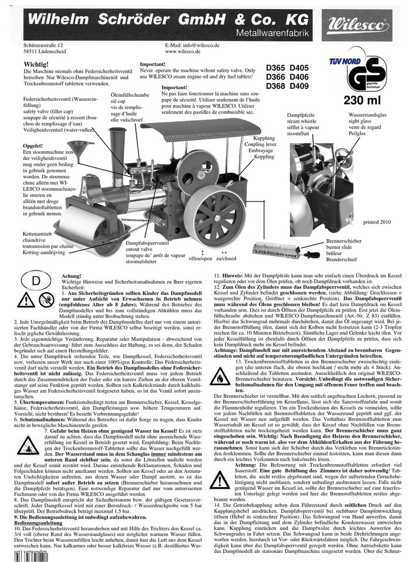
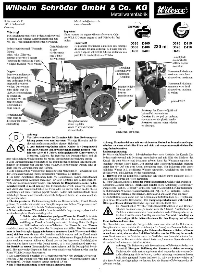
Important information and safety precautions!
1. For safety reasons, children (recommended age: 8 year and above) should only use the
Steam engine under adult supervision. (Because of steam pressure, hot boiler, hot steam pipes
and flames etc.) Do not leave the steam engine unattended either during operation or whilst the
engine is cooling after operating.
2. If any problem occurs with the steam engine, the matter should only be dealt with by a distributor
or the WILESCO factory. Attempts to repair by other persons will invalidate the warranty.
3. Any alteration to the Standard specification carried out by persons (other than WILESCO Agents)
will also invalidate the warranty.
4. Only WILESCO genuine parts or accessories should be used (boiler, spring loaded safety valve
etc.) as these have been factory tested. For safety reasons, the spring safety valve must not be
adjusted. It is illegal to operate a steam engine without a spring safety valve. Always check the
valve for correct operation before use.
5. High temperature: The principles on which your steam engine operates mean that the burner
tray, the boiler housing, the spring loaded safety valve, the steam pipes etc. become very hot. Do
not touch, in order to avoid the risk of burns!
6. Safety precautions: Do not touch and in particular do not let the children touch any of the moving
parts while the steam engine is in operation.
6a) In the case of an emergency or if the engine has to be moved, the model can be lifted by the
roof.
7. Do not heat the boiler without sufficient water! Always ensure that the steam engine
has sufficient water in the boiler during operations. Also check the water level carefully when
adding new dry fuel tablets. The water must be visible at the lower end of the sight glass
(minimum). If this instruction is ignored the boiler will be damaged and has to be replaced. We
will not accept any claims whatsoever, including consequential damage, in this matter. If a
leak occurs in the boiler, or any other part, stop using the steam engine immediately. Any
necessary repairs should only be carried out by trained staff, of at the WILESCO factory.
8. The steam engine meets all safety standards and requirements. Every boiler has been submitted
to a bursting pressure and water test of 5 bar (approx. 71 psi). Boiler content 240 ccm, operation
pressure 1,5 bar (21 psi).
9. Please keep the instructions in a safe place!

Operating instructions:
10. Unscrew the spring loaded safety valve and, using the funnel, fill the boiler approx. full (upper level
to the sight glass) with hot water if possible. Raise the funnel slightly when pouring in the water so
that the air can escape from the boiler. Use boiled water or rain water if possible (low chalk
content).
11. Note: The steam whistle can be used to check for any overpressure in the boiler or, before oiling,
to check whether the boiler is still under pressure.
12. Close the steam cut-off valve before oiling the cylinder. The valve is closed when the lever is
below approx. 45 deg pointing backwards (towards sight glass) and open when the lever is below
approx. 45! Pointing forwards (towards smoke stack). Now unscrew the oil filler screw and fill with
WILESCO steam engine oil or car engine oil while turning the flywheel several times so that the oil
is drawn in. Oil frequently so that the piston does not seize. 2-3 drops of oil are sufficient for
approx. 10 minutes operating time. For safety reasons the steam cut-off valve must be closed
when oil is being added. There must not be any steam pressure in the boiler. Lightly oil all the
bearings and linkages. Before refilling the boiler with water, the pressure in the boiler has to be
released by opening the steam whistle.
13. Place two layers of ESBIT fuel tablets in the burner slide, the lower tablets flat and the
upper tablets on their sides. Then light the tablets. Never use more than 4 fuel tablets at a time.
Use only the original WILESCO burner slide. Caution: Because of the risk of danger from an
open flame, always take the necessary safety precautions. The burner slide is adjustable. The
oxygen supply and the flame height can be adjusted by moving the burner slide in relation to the
air holes (see illustration). Before adding new fuel tablets always check the water level and refill
the boiler with water to ensure that the boiler does not run dry. The ratio of fuel tablets to the
amount of water in the boiler is designed so that the boiler cannot run dry without fuel tablets being
added. The fuel slide must be completely pushed in. Important: After completing the heating
process, remove the burner slide from the guide whilst it is still hot, otherwise unburned fuel
may cause the slide to jam. If the slide becomes jammed, it can be removed by tilting it slightly to
the left or right. Widen the guide slightly using a standard pair of flat pliers.
Note: ESBIT tablets require plenty of oxygen to burn properly. This means if used indoors the
room should be well ventilated. To prevent unpleasant smells, the fuel tablets should be allowed
to burn out they should not be blown out. If there is insufficient water in the boiler, place the burner
slide on a metal plate until the tablets have burned out completely.
14. Disengage the gears next to the driver cab, by moving the clutch lever sideways. When the water
starts to bubble open the steam valve and turn the flywheel by hand, so that the condensation in
the pipe and cylinder can escape. Engage clutch and put steam engine into operation, by gently
spinning the flywheel. The flywheel can be started-up in either direction, which enables forward
and reverse movement. The speed can be adjusted by means of the steam stop valve.
15. The exhaust steam which does not escape through the chimney collects as water-oil-condensation
in the container under the chimney, which is why the steam pipe is not soldered, since no pressure
develops in the condensation container (separate from the boiler). After using, remove the
chimney and remove the condensation through the chimney hole, by banging lightly.
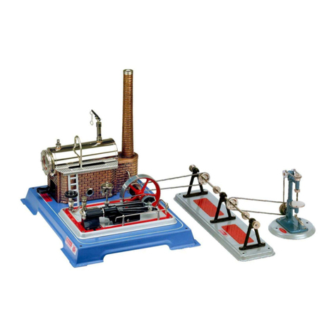
16. The Steam Roller (and Traction engine) can, with the clutch disengaged, be used as a stationary
steam engine. By using the belt drive on the flywheel, the WILESCO range of driving models can
be operated. When the Steam Roller is used as a stationary engine the clutch must always be
disengaged.
17. After use, remove any water left in the boiler. Be very careful if the water is still hot! Any water
left in the boiler cannot do any damage, but might leave sediment on the sight glass. Any soot
formation on the lower surface of the boiler can be removed with a brush, e.g. an old toothbrush.
Finally, dry the model using a clean cloth. Never remove chalk residues on the sight glass with
vinegar.
Warranty:
18. Finally, a few comments on the warranty. All WILESCO steam models are carefully checked
before leaving the factory. However, if a problem arises, we will be happy to assist, or carry our
repairs. You can return the steam engine directly to WILESCO or to the distributor. We are sure
you will appreciate fired models cannot be exchanged, but we undertake to repair any fault.
The above information has been given for you to obtain the maximum enjoyment from your steam
engine WILESCO wishes you lots of fun, and Full steam ahead?

Remote control is available for fitting to the steering wheel of the Steam Roller and Traction
engine; the part no. is Z361 and can be ordered via your WILESCO retailer.
Text & illustrations: Wilesco Wilhelm Schröder GmbH & Co., Germany

Assembly Instructions
Steam Roller D375, D376, D377 & Traction Engine D415, D416, D417
The Functioning of the Original Steam Engine
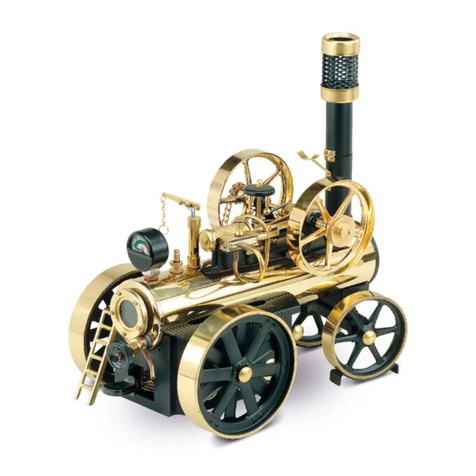
The driver of the steam engine or stoker shovels the coal through the stocking door into the boiler. The
coal is being burnt.
The boiler/firing chamber is supplied with fresh air via the air supply from underneath. The combustion air
which is heated to high temperatures moves from the boiler through the steam tubes of the boiler (water
tank) into the combustion chamber and from there to the chimney. This is how the steam pressure which
accumulates in the enclosed boiler is transferred in the cylinder into motional energy. The exhaust steam
(condensation) is led via the exhaust into the chimney. The evaporated water is replaced by fresh water
from the cold water tank. The motion of the piston rod is transferred by means of the crankshaft and the
gear wheels onto the large rear wheels. Every steam engine has, as opposed to a steam locomotive, a
large flywheel.
The flywheel is needed in order to overcome the dead center of the piston in the cylinder and serves also
as energy storage to absorb load surges. In contrast to the steam engine the steam locomotive has two or
more cylinders whereby the offset piston arrangement overcomes the dead center and for that reason a
flywheel is not required.
The WILESCO-steam engines/traction engines work on the same principal as the old originals. However,
instead of burning coal or coke a dry fuel tablet is used to heat the boiler.
Text & illustrations: Wilesco Wilhelm Schröder GmbH & Co., Germany
This manual suits for next models
5
Other Wilesco Toy manuals
Popular Toy manuals by other brands

Hasbro
Hasbro TRANSFORMERS BUMBLEBEE manual

Fisher-Price
Fisher-Price Sweet Magic Kitchen instructions

Black Horse Model
Black Horse Model T-28 Trojan 120 Instruction manual book

Renaissance Learning
Renaissance Learning 2Know Setup guide

Mattel
Mattel Monster High W2556 instructions

FLYTEAM
FLYTEAM FREE BEE manual